write data to multiple channels.
Hi all
I have a problem with writing the data to a file.
I'm writing a unique 2D array (containing 3 different signals) in a file LVM.
but for some reason, data is stored as three samples of a channel, I have not been able to put it so that it divides the data into three different channels. Someone an idea how can I spend it?
The incoming 2D table seems good.
Thank you very much in advance,
Keksbold
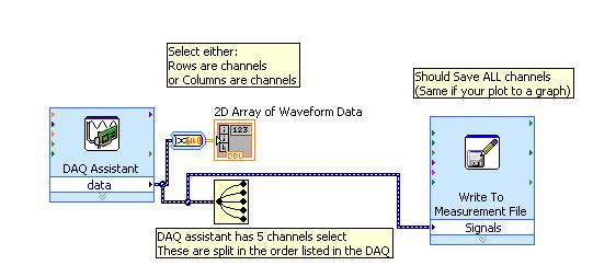
Assumption: Each line of your data is a sequence of N samples. Your 2D array must pass through a vi "Convert Dynamic Data". Right click on "Convert a Dynamic Data.vi" and choose: 'table 2D of scalars - lines as channels.
Or postal code if it's not useful.
Tags: NI Software
Similar Questions
-
Tracing and recording of data from multiple channels (and tasks)
I have two modules in a CompactDAQ chassis:
-NI 9213 (TC 16 channels)
-NI 9203 (8 current)
I'm using LabVIEW 11, data acquisition both of the modules without problem. I am, however, having trouble with the tracing and recording of data. Is there a method to combine the tables 1 d of waveforms from each of the two tasks, so that a waveform chart can accept? In the same way, I can write them to the same PDM or the file lvm?
The tasks use the same synchronization settings, which shouldn't be a problem. It is 1 to 10 Hz, so I have no major concerns regarding performance.
I'm new to the Forum, so I apologize for any misstep in terms of etiquite. Thanks in advance for the help.
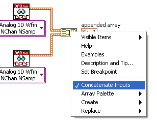
I might be misunderstanding your question, but why can't you just use the 'build' array function to combine your two bays of waveform? Click on 'build array' and select 'Concatenate' to add one table on the other.
-
Place the data of multiple channels in the tables
At this moment I have a sample program with a value of 8 data channels of my USB-6009 spitting in a graph of a waveform, which looks and works very well. Ideally, I would like to take this data and manipulate it to produce two calculations before it comes out on the graph. After I would handle that I want to display on a line chart (cloud?) as two lines of updated permanently. I think if I can get my 8 channels in 8 separate tables, the rest should be put in place.
Thank you
Hi Iwild,
How you import your data? You place data in a table in a first time?
You use NEITHER-DAQmx? If so, please see this document that goes over how to use NOR-DAQmx with text-based environments.
Best regards,
-
How do switch you between multiple channels to indicate which channel to acquire the data from?
I'm trying to builld a VI where I can have an option to enable or DISABLE multiple channels depending on the modules plugged into the chassis and then acquires the data of the channels which are turned on and where other acquisition parameters do not change. Is there any specific/switch where can I do this? Please answer as soon as possible. Its quite urgent. Thank you
You use DAQmx? To change the assignment of the data acquisition channels, you must close the currently open session and then create a new session with the new channel definition. So the order of execution:
Create task or virtual channel - read - clear task of triggering and synchronization of the configuration - set new channel list and to create a task - read - clear task, etc...
-
DAQmx showing not readings to multiple channels
Hello
I am trying to acquire values of temperature of 3 consecutive using a task DAQmx channel as shown in the attached photo.
I have a loop of producer-consumer for fast reading and writing samples in a file.
To specify the channels, I typed in the box connected to a terminal of "physical channel" (not shown in picture) as follows:-SC1Mod2 / ai2:4. This is to acquire a reading of analog channels 2, 3 and 4. The program must then write a file reading on channel 3.
The code works perfectly if I purchase samples of 1 channel only.
When I try to acquire multiple channels, I don't see readings on one of the task of acquiring Wired Digital indicators.
I would appreciate your input on what might be wrong with the code.
Thank you.
kumv10 wrote:
The broken wire seen in the photo is the result of adding more channels to the task of acquiring. I managed to get around this by specifying a different, but even with an intact wire data type, the program is not displayed readings since the 2 remaining channels.
Instead of use for dynamic data Type, then the channels Split, just use an array of Index to get your three values.
-
Generation of series in multiple channels
Hi forum, I need to ask a few questions. Any help is appreciated.
(1) I need help with the generation dynamic series in several channels. Here, we can see how the dynamic data set generated by a single channel. But I can't find anywhere, how to generate several series signals in multiple channels.
(2) what is the limit for this generation series? I think it depends on the material, but I don't know, what is the limit. My hardware is SMU-6544.
(3) it is possible to generate different signals in different channels using scripts? and to start the production in these channels at the same time? the example given in the script generation labview is unfortunately only for the generation of a channel.
Thanks in advance,
Kind regards
Yan.
Hi Yan,
Produce on several channels with multiple data is difficult without a tool to view the data, or series of each channel bitstream concatenated into a software ADE and transposed before be downloaded into memory. To make Visual things here, I'll assume that you want to generate a pattern of 3 bits on sample of channels 0, 1 and 2 is 8 wide. Assume the following models of the series bit for each channel:
ch 0: 0101 1010
CH 1: 0000 1111
CH 2:0100 1101
So the question now is, how do you load this in the SMU-6544(or any other HSDIO hardware)? Of the two options, you can use Digital Waveform Editor (NEWS) to create visually and save to a file type HWS then load a DJ using the API HSDIO. It is the easiest in my opinion.
The second way is construction examples of data based on a basic example. I want to say is you take it all binary streams and built a 2D table so that it looks like:
01011010
00001111
01001101
An array of 3 x 8 and then transpose the table that turns into:
000
101
000
100
111
011
110
011
Here you can see we have 8 lines, each line is a sample, and in the form of U32 read in decimal, you get 0, 5, 0, 4, 7, 3, 6, 3. That's what you can load into our niHSDIO U32 function write a waveform. I hope you can see how this translation occurs and how it looks like in terms of load on the jury. Each sample usually contains data for all channels, where each bit in the U32 is one of the 32 channels available on your device. So if you want to write a '1' on Channel 5, you would load a value of 0000 0000 0000 0000 0000 0000 0010 0000 in the form of sample, where the 5th bit is 1 and all the other bits 0. In decimal, you would write '32' value.
With regard to the limitation of the size of series, if your flow rate is slow enough you can disseminate and make an almost endless stream, but assuming that you are running at the maximum rate, your series of waveform size is limited by the size of your on-board memory. Since each sample generation is 32-bit, which is 4 bytes for example, if a memory size of 32 MB will correspond to 8MS bitstream series max.
For any questions or comments are welcome. Thank you.
-
Replace negative values in multiple channels with "0'.
Hello
I'm calculating and then by creating a cumulative channel, multiple channels. Negative values in these channels aren't necessary, and I need a nice way to replace each negative value in these channels with a value of '0'.
My current code is:
Do
Do
If Data.Root.ChannelGroups (2). Channels (i). Values (II)< 0="" then="" data.root.channelgroups(2).channels(i).values(ii)="0 ">
II = ii + 1
Loop until the second > Data.Root.ChannelGroups (2). Channels (i). Properties ("length"). Value
II = 1
i = i + 1
Loop until I > Data.Root.ChannelGroups (2). Channels.CountIt works, but I don't like. He adds a few seconds when running my script, which was almost instantly. Is there a better way to do it?
Thank you.
Hello Kevin,
The fastest way to go through a channel and check the values less than or equal to 0 is through the canal's calculator. The code below takes all the channel first channel group (with the exception of the first string that is be the weather channel in my example data set) and replaces the values<0 with="" 0="" through="" the="" iif="">
Set Group = Data.Root.ChannelGroups (1)

iMax = Group.Channels.Count

FOR i = 2 to iMax

  Adjust the strings = Group.Channels (i)

  Formula = "= IIF (y '.<0, 0,="">

  Call to calculate (formula, Array("y"), Array (Channel))

NEXT ' I
In this example we overwrite the existing values of data channel with 0, but you can also copy the channels to make sure that your raw data is available.
The calculator of channel is extremely fast for this type of operation because it does not create a loop to go if each line separately and check the values he...
I hope this is useful,
Otmar
-
DASYLab Write Data Module output Format
When writing the fields in an output file in ASCII mode with the option writing data Module and copy entries, entered the order in writing? Or, if the output field order can be changed? I guess the order of the output being written is 0. n. I can redraw the module so that the entry order corresponds to the order of output you want, but it makes the messy Visual design. I would like to be able to specify that the entries (copied to the outputs) are 1.n and written as 0.. n-1 and the 0th entry is written to the nth output. If I can manipulate their order in the module or do I redirect the entries to match the order of final output?
Thank you
The list of strings in the target file is determined by the entries in the module. They are always written 0... n.
There is no way to change the order inside the module. You need to link the entries in the order you want to that they have written.
The option of copy entered in any module is simply a way to keep tidy worksheet. It allows to "pass" the module. No processing is done, and the output channels are exactly the same as the input modules.
Checking the option in the module to write data does not affect the file that is created.
-
Through tunnels of automatic indexation to write data files?
Hello
I use neither-controller to control a servo and position and torque data collection. I want to write data to the TDMS files.
Recently, I learned about the design of producer/consumer model and I thought it would be a good approach to ensure that writing the files didn't slow down my timed loop of data collection.
However, I also realized that my program seems to work well if I wire the data that I collect the tunnels of automatic indexation. Can I use a structure that executes only after the entire collection of data is made to write the charts that I built to TDMS files.
Is there a reason that would make the last method against? Can the tunnels of idexing auto slow my loop enough to concern him? I collect only about 5,000 points of data for each channel.
See you soon,.
Kenny
In my opinion, the main consideration is timing. If you use consumers/producers, you essentially make writing while the data collection process is "pending" the next item to collect. It should be the case that the consumption will be faster than production, so at any time, 99% of the data are already written, Yes (perhish forbid!) if the program crashes, you already have most of the data on the disk. fo
Alternatively, you can use the tunnels and send an array of 5000 points (from the tunnel exit) for the writing process. This requires it to be rather than parallel series - no writing occurs until all the 5000 points are generated, and the writing process, instead of is almost as soon as it starts, takes 5000 times longer (more or less).
The series is 'simpler', especially for a beginner. The producer/consumer, if you understand the design model, would be my preference.
BS
-
Dynamic data of several channels in table, then save in Excel
Hello
I am acquiring data from several channels (4-5) and I'd like to collect samples at low rates (10 Hz for 3 minutes max). For various reasons I use Dynamic Data type, although I know that it is not the best way (some say it is a wrong data type
 ). I also want to save data to a file (the best option would be data excel file).
If I acquire data 10 times per second, it is quite slow to save in excel (this is the slowest option of all types of data). So I would like to fill a table or matrix of acquired data and then write Excel file (I use scripture to measure file). But I don't know how to do - if I convert DDT in DBL, build an array and connect it to change registry, it works but I lose the information in column names and I'm wasting time. If I connect to build the table a DDT and then shift record another, it returns the table 1 d of DDT. I would like to have 2D DDT, which collects all the information loop. Is there a suggestion how to solve?
I'm sure it would be easier solved my problem with the double data type but I also use select signals VI which is the VI I am not able to replace at this time.
Good day
Lefebvre
I don't know if there is a question here, or what. Doing what you say you want to make, acquire the data of 4-5 channels at low rates (10 Hz for 3 minutes) and save the data in an Excel file (I assume you mean really Excel, i.e. a file with the extension .xls or .xlsx) is really a very easy thing to do in LabVIEW, especially if you are not using :
- DAQ Assistant
- Dynamic Data
- Write to the action file.
Indeed, you seem to realize this, but I guess you want to 'do the hard', in any case.
Good luck.
Bob Schor
-
TDMS multiple channels, frequencies of different sampling
I'm developing an application c ++ under Windows 7, which must record the sensor data acquired on the disc. The data consists of approximately 1 500 channels sampled at rates that vary between 100 samples/s and 1 sample/s with data types which could include the floating, whole, decimal point fixed and boolean. We need log on without interruption for hours at a time. In the past, my company has used LabWindows/CVI to write TDMS files for this kind of application, but the number of channels has always been much lower and all channels, we sampled at the same rate. I was instructed to use the LabWindows/CVI/PDM solution for this new effort, but I have concerns about the way in which it will occur in the conditions I described above. My questions:
* It OR application notes dealing with best practices for recording several channels of data sampled at different rates for TDMS with LabWindows/CVI files?
* Are there performance indicators which show the capablities and the limitations of LabWindows/CVI/PDM in conditions similar to those I describe?
* Someone here any experience – positive or negative – with TDMS in a similar application which they can share?
TIA
Hugh
I had an Exchange offline with Technical Support OR on this subject and received the following guidelines, which I consider the Gospel:
You should be able to connect to TDMS in CVI for your strings from 1500 to different rhythms without problem provided that your computer has enough memory. You can set up groups and with 1500 channels you should probably, in the interest of the Organization, but it is not necessary to create groups to limit the number of different sampling frequencies. Alternatively, you can generate different files to separate data, which are also recommended, but not necssary, based on your preference for the organization rather than the need for the maintenance of sampling together in the same file. TDMS supports asynchronous writing, so you should be able to connect different channels at different rates for the same file without errors in access to the files or something like that. One thing, you might encounter is slowing a lot of simultaneous writing. I found this example of community which shows how to write data to disk faster using the advanced TDMS API. Please visit the following link: LabWindows/CVI Tip: write data to the disk faster with TDMS Advanced API https://decibel.ni.com/content/docs/DOC-33401
-
Dedicated for each channel from multiple channels in a single task task disadvantage
Hello
My current acquisition software (C + c++ / GCC) encapsulates the methods rather clumsy niDAQmx C to interface with the data acquisition equipment in a class that represents a task of acquisition. This way I can create several instances, for example counter input, analog input, analog output, their terminals and the class supports all work low level as ensuring input analog fake internal is started if there are only counter entries such as the sample clock starts, or configure reminders N-sample, etc.
It seems to work very well, and also the time seems to be good, because first of all the tasks on multiple instances of my wrapper. For triggered early, that I use
DAQmxCfgDigEdgeStartTrig(mTask,mTriggerTerminal.toAscii().constData(),DAQmx_Val_Rising)in-house.
Now my real question: what is the advantage of multiple channels, when everything seems to work fine with multiple tasks and only one channel per task? I don't see the disadvantage, it would first classify necessary acquisitions in types (I, ao,...) because several strings in a single task must be of the same type. With my approach I need not care because each channel still gets its own task.
I don't know I'm missing something here. Maybe someone can explain it to me, maybe some limitation of multi-tasking, I have not yet read.
Hey!
Unless you specified for managing the it (simultaneous sampling) or modular instruments and hardware devices (see link )
You cannot perform two tasks at the same time that access to the analog inputs, for example, because the
ADC is a shared resource that is connected to a multiplexer, and that only one task can work in it at a time given. (see here )
Similar restrictions often apply to other types of operations.
I'm not aware of any performance issues, perhaps a little more memory could be used.
So as long as your hardware supports what you are doing, you should be ok, I think,
and it is only a question of clarity and intelligibility, ease of use and structure.
As you use classes, I'm sure you've heard about encapsulation - so it is a
question of how you want to design your application.
In addition, when you work in LabVIEW, tasks feel more natural to the principle of data flow, because you have a thread for your data acquisition,
and it works very well with our modes of standard design.
So, if it is better for you (and works with the hardware), you can give all the channels its own task.
Hopefully this might clarify some things,
Kind regards
Rome
OR Germany
-
Hello, I have another problem here, just started to learn the filtering and decided to practice on the job making, im if you have this one question: I have two signals on channels of entry of two pressure sensors that come with high noise. I tried to split the signals, filter, and then merge again to send to waveform, but it does not somehow, and I thought that if there was a specific filter for multiple channels, I read that some TREES can divide signals itself and merge them automatically, but I couldn't find one. suggestions for beginners? Thanks in advance
PS by the way, managed to filter one of the signals manually split and for some reason, the waveform to the display of the data of pressure with sound sensor stops working after apprx 3 sec, it kind of drags a bit and then goes black blank, so any suggestions on this point, would much appreciate
PPS two graphics of waveform showing the initial data of the sensors go blank after a while at the same time black

Hello Pomplamoose,
I forgot to mention something: If you set playback VI to N samples then wire a constant for the number of samples per input channel. A good way would be to read in samples of 1000 per iteration.
Part Fliltering:
First of all, if you want to filter the high sounds you use Lowpass Fliter.
Attached you will find your VI with 2 ways how you can filter your signals.
(1) easy solution with express filter VI.
(2) VI of Butterworth filter, the way in which you the tried.
Some explanations to 2):
If you use the butterworth VI as a low pass/high pass filter filter, it ignores the entrance of high cut-off frequency. The entry, you should use is the lowcutoff FREQ.
In VI I provide you with there is no synchronization of the signal information once it is filtered, because you only use data of Y of the type of waveform. If you have calendar information in your signal you could do that with the construction of a waveform type after you filtered the data Y.
Therefore, you have no synchronization of the signal you need to resize the chart you can see the filtered together signal.
To merge the signals after you their filtered, you have 2 ways:
(1) build an array of filters.
(2) use the signals of fusion VI.
If you need help just ask, otherwise mark as resolved.
Kind regards
Markus Mayr
-
I did separate VI for reading signals from several channels on a map of NI USB-6251. I would like to combine these in a VI VI alone so that they can run that at the same time, however, there is an error if there is more that a single DAQ Assistant in the same--> error-50103 VI was held at DAQmx controls Task.vi:32 (the specified resource is reserved. The operation could not be performed as indicated.)
All the inputs of channel must then be read in with a single DAQ Assistant, but all of the data on different channels are not separated. Can save this data in a matrix or otherwise manageable which allow to facilitate the analysis of the data from the separate channel entries?
I tried to view the data in a file of measures, but then when I tried InPort data, I could all the data I wanted.
Hi AggieGirl,
Good afternoon and I hope that your well today.
First of all, you will not be able to have more than one DAQ Assistant by input analog or analog output task because the device has only one of each. So, you must have a DAQ task to HAVE and AO. (This is not the case for DIO static).
There is far from split signals using the express VI - signal splitter.
When you say you saved this file and it does not work, how it did not work? The Express VI - save a file of measures needed to manage multiple waveforms. Can send you your code & explain more about what was not OK on the file?
Thank you
-
L50-A-19N satellite can not read audio data from multiple sources
I can't read the audio data from multiple sources. It is very annoying when I have 2 youtube videos, playing, if I start playing something on the media player, there is no sound on media player, it's the same when I have 2 open media players and 1 youtube video playing, youtube video has no sound...
It disappears when I plug my headphones...I already have all the latest drivers, the DTS driver was last updated was in 2014, his day of February of this year...
25/02/14
DTS Inc.
Windows 8.1 - 64 Bit
1.01.2700
I don't know if this has the feel, but I had his most recent DTS driver that I found, it is not my laptop model, but they all seem to be the same - v1.1.88.0
I uninstalled the DTS software and still had the same problem, then it is irrelevant on its driver somehow...02/10/15
Integrated Device Technology Inc.
Windows 8.1 - 64 Bit
6.10.6491.0
Audio driver IDT has more recent release date, but the version of the driver is the same as the 2013 one...
Why the older drivers of toshiba releaseing as 'NEW '?
2nd is my Advanced settings speakers, nothing has changed when I disabled "allow applications to take exclusive control of this device.
Sorry but I don't understand your problem.
I tested it on my machine and if I start the music on three different sources (YouTube, player, web radio) I can hear all together, but it makes no sense to listen to music from different sources.Or how do understand you?


Maybe you are looking for
-
How to store the navigation history when updating Linux?
I am using Puppy Linux 528.005, used FF11 until I upgraded to FF14 & always I updated the browser I'm losing my browsing history. This info is saved somewhere where FF can he get everytime it starts, so I wonder why the FF upgrade involves the loss o
-
How to open my email links in the current profile of FF?
Hello I made a shortcut to allow me to choose a FF profile each time I want to use FF. Here's the code: "E:\Program Mozilla Firefox Firefox\firefox.exe" - profilemanager-no-remote I also put a FF default browser. My problem occurs when I'm clicking o
-
the App store shows 14 applications need to be updated, but when I try to update it shows no updates
icon App store from my iPhone shows there are 14 necessary updates, but when I click the icon, it shows that all apps are up to date.
-
How 'add to home screen' a website on MBP 2015 icon
How can you "add to home screen" an icon of MBP 2015 website. All I can find on my MBP is "add a bookmark!
-
Very strange Sample & Hold behavior on image signals
Hello Here is video fragment on the behavior of my installation of video capture.