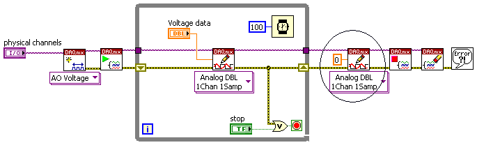
Writes a single analog waveform to the pxi-6363
Hello
I want to write a fixed set of samples to an analogue output, then stop. I use c#, but this isn't important. I don't want a continuous signal. Let's say I have 1000 samples / second or one sample per 1 ms. I want to be able to generate simple signals of anywhere from 10ms to 1000ms wide. The shape is arbitrary, but once the samples are made I want to stop and stay on the last written sample.
I generally synchronous writes, i.e. the .write is blocked until the end. I need the start and end of the generation of signals to be deterministic.
I have not found a way to do this. It is refreshing to be or if I said do not regenerate I get an error of-200290. I don't want to regenerate, and I want him to stop pending for other examples.
Hello johngardner58,
Looks like you are currently your task schedule configured to generate samples continuously, and because you send only a fixed set of samples, the buffer is regenerating those samples to keep continually generate samples.
For your application, it seems that affecting your finished samples task calendar may be a better fit. This will send the lump sum of the samples that you specify, and then stops.
This can be done in the property Task.Timing with the SampleQuantityMode.FiniteSamples for the parameter.
Here's a tutorial on the calls and the configuration options you have while Using NOR-DAQmx in text-based programming environments.
I hope this helps!
Tags: NI Hardware
Similar Questions
-
How can I display an analog input for the PXI-5105 on LabVIEW?
Hi all
I am very very new to LabVIEW and I started to tinker with it. I use the version of LabVIEW 2010 SP1 on Windows 7 OS. I also have the chassis NI SMU-1073 with SMU-6361 and PXI-5105 modules and the chassis is connected to my PC via PCI. I became familiar with the devices and trying to see some analog signals to one of the channels on the PXI-5105 module in a graph in LabVIEW.
I would appreciate your help.
Hello Henokview!
I would like to read through these tutorials to understand the steps of programming of the NOR-SCOPE, NOR-DAQmx. After reading these links below, you will be able to understand how to connect the output of a readfunction to a chart or table.
DAQmx
http://www.NI.com/white-paper/5434/en
OR-SCOPE
http://www.NI.com/white-paper/3382/en
Best regards
Jonas
-
How to write a single line instead of the entire port?
Hello
I followed the example for writing to the digital line as follows
int taskHandle;
given int [8];
char linename [] = "" dev2/port0 / line0:7 ";"
DAQmxErrChk (DAQmxCreateTask ("", & taskHandle));
DAQmxErrChk (DAQmxCreateDOChan (taskHandle, linename, "", DAQmx_Val_ChanPerLine));
DAQmxErrChk (DAQmxStartTask (taskHandle));
DAQmxErrChk (DAQmxWriteDigitalU8 (taskHandle, 1, 1, 10.0, DAQmx_Val_GroupByChannel, data, NULL, NULL)); Here the data have 8 digits
Error:
SetWaitCursor (0);
If (DAQmxFailed (error)) DAQmxGetExtendedErrorInfo (errBuff, 2048);
If (taskHandle! = 0)
{
DAQmxStopTask (taskHandle);
DAQmxClearTask (taskHandle);
}
If (DAQmxFailed (error)) MessagePopup("DAQmx Error", errBuff);The example above shows how to write 8 binary to 8 lines, but how to write only one line? I try the following code, but it does not work
char linename [] = "dev2/port0/line 2;
...
DAQmxErrChk (DAQmxWriteDigitalU8 (taskHandle, 1, 1, 10.0, DAQmx_Val_GroupByChannel, & data [2], NULL, NULL)); Here the data have 8 digits
The data format for the DAQmxWriteDigitalLines() function will do exactly what you want.
The data format for the DAQmxWriteDigitalU8() function is a full port (even if you do not have a value of a harbour full of lines in your task).
-
How do I synchronize pxi-6341 analog output to the analog in pxi-4304
I have an SMU-1082 chassis that contains a high-6341 and a PXI-4304 module. I went out a sinusoidal signal of pxi-6341. AO.0 channel for the pxi-4304. Channel ai.0. The pxi-4304 isn't receiving all signals up to about 75 MS later. How can I synchronize synchronization between the 2 modules together to stop this loss of data?
(Finally, I run a waveform digital off the 6341 and in a device while the 4304 captures analog response from the device. "So I'll need to have all sync'd up).
Thank you for your help,
Ron
After trying many "tricks" with various DAQmx screws, I finally found the solution. I simply had to stagger the 'task to start DAQmx' between the entry and exit, as shown in the attached photo.
Hope this helps someone.
-
Import MATLAB generated the file ascii in the Analog Waveform Editor
Hi all
I tried to create signals by the Analog Waveform Editor. I have some Waveform generated from MATLAB and recorded as ASCII files, following the instructions on this Web page OR, but it did not work properly. For example, if I produce a column to fill with 0.5 and import the file into the analog signal generator, all I get is a huge series of random number. I missed a few steps in the import of the waveform?
Thank you!!
Just for your reference, I could almost in half the size of your file just by saving as .hws. Also to answer your last point, you may have issues opening / importing your .txt file because it may have been opened in another program at the same time. Make sure that you have closed it in Notepad or Excel or other programs which may still be locking on the reference.
Kind regards
Jason L.
-
Hello
We use the DMM and SMU-6363 map to test a hardware device. We will also use a PXI-2530 b switching matrix. We will use the digital multimeter to perform the measurements of voltage, DC and AC, measurements of impedance (2-wire and 4-wire), frequency and waveform acquisition. Can the PXI-4071 left be 4 wire connected (black jacks taken connected and red connected) mode and still be used to perform all other measures (including 2 impedance of the cable). This would simplify the switch connections.
Current measures use the son + and LO, but the HI and S-can remain connected. The problem you are having is if you have an active device the digital multimeter and take you a 4-wire resistance and the measurement of voltage with all 4 wires connected and then change to a current... When you do this, short-circuit you the terminals of the DUT, on that you just take the measurement of the resistance. If the terminal HAD, say, a power supply 10V, then you have just shorted out. Of course, this isn't a problem if your Instrument is a passive device, or if you change just the unused two lead whenever there is an active device of low impedance.
If you want to make voltage, current and 4-wire resistance, you need all 4 wires. If you want to do the voltage and current, you will need 3 wires, but you could connect the s + Hi and then just do the two wires. I vote running every 4 son to your DUT for maximum flexibility.
2-wire resistance is a must if you are measuring resistance above 10 MOhm. Alternatively, you can use 4-wire for all measures.
-
I am trying to simulate a radiation of 3 mV/V power pressure transducers (excitement is + 10V, full range should therefore be 0mV at 30mV). I am looking for a PXI analog output device high number of channels (PXI-6723, possibly) who doesn't have the down side of the analog output channels linked to the land of installation (differential channels of AO). The plan was to use a voltage across the divider circuit of +/-10V output card AO to +/-50mV. I use a card AO 16-channel, 12-bit which has all the Commons AO related to the mass of the PXI chassis and Earth installation. The DC of the signal part I want it, but there are about 80-100mVpp of noise (from the ground connection) riding on it. I also tried a PXI-6115 card we had at hand and its reference AO are related hard chassis-same result with the noise of the Earth. Is PXI - 6723 AO GND isolated from the land of the chassis/installation? Even if all GNDs AO are shared on the Board, this solution should be much better than having a noisy ground reference.
Any ideas? Alternatives to simulate a floating, the millivolt output device?
Thank you!
The reference of the AO of the 6723 relates to Earth; pages exit track to track analog insulation research, only a handful of AO devices have an isolated field (the business is a low channel count).
-Ciao
-
I need to transfer a voltage using a PXI-5421 signal before a Council of PXI-2576 and then transfer it to an another Committee of the PXI-2576. For example I had set the signal of the ARB has then put 16 CH MUX 1(1st Switch), the value CH MUX 3 0 (switch 2) then read the MUX 3 voltage using a PXI-4071. I know that I can use the example of DMM Switch Handshaking.vi niSwitch for the rear. I'm just not sure how to transfer data to MUX 1, MUX 3?
Thank you
Denise Barajas
Hi Denise,
You must connect two switching modules to the outside. Signals may not actually be transferred through the PXI chassis backplane. Bottom of basket can only be used for communication by PCI bus and for the delivery of the trigger. You need to use external threads to physically send the signal of the first PXI-2576 to the second.
There are two ways to connect signals to the PXI-2576, you can use a block of endings that mounts to the front of the module PXI, or you can use a cable with a block of external connection. You can then connect the signal cables to the connectors to screws on the terminal/connector block. More information about the options of connection to the NI PXI-2576 connectivity products Page.
Hope this helps!
Chris G
-
Single channel match trigger speed model vs onset of edge on the PXI-6562
I think that my question boils down to this: what function does the edge of trigger plan that is not provided by the model match trigger?
As far as I know, the only differnece on the PXI-6562 is the edge trigger has its own pins dedicated (PFI pins and pins RSTI) to detect a trigger, while the model match trigger detects a rising edge or falling on a regular input pin.
Is there a difference in performance (for example, the time to rearm)?
Are both triggers synchronous types with the sample for dynamic acquisition clock?
On my application:
I acquire a signal off a SPI bus, triggering the CS line. I start to acquire data when the CS line going down and stops when the CS line is high. As I acquire data CS on a regular supply, it seems logical trigger on a pattern for this channel only match. I'm curious to know if there is any advantage to connect a PFI PIN to my CS of entry so that I can start using digital edge type.
Thanks in advance,
Arthur
Arthur,
There is no difference with regard to performance using a digital camera compared to a type of pattern match trigger. Specifications for rearm time reference to the trigger type (Start, reference, etc.) in the samples to rearm, and there is no difference with the performance when you use a digital advantage over a line/PFI line Trigger and a correspondence to the model used on the input signal. Change the source of the trigger itself will not change the performance of the material that occurs after the trigger is received. This behavior to sync with the clocks of acquisition regardless of the input source. We're just looking at different sources for the jury to look for a given trigger.
-
Memory of the PXI - 6562 Max per channel
I have two questions.
I have a PXI - 6562 and a data set is 256 MB (32 MB). I want to send the data in this dataset on a single axis of I/O serial. basically, I would like to spend my little of a set of data at the same time on both edges of the clock on an axis of IO. I don't like on the other IO pins. Is this possible with the PXI-6562 or all bits in each octet in the memory of the card corresponds to a specific channel.
If I can't send my data in series then I will accept that to encode every bit in my data set in the form of byte with a bit of data and the other zeros. This means that, for a set of data from 256 MB, I would need 8 times more memory 2048b. I understand that there are a total of 2 GB of RAM on the PXI-6562. Is this all addressable RAM in series? I can write the data of all the 2 GB of RAM for say 8 i/o ports?
gtg811q
With the PXI-6562 even if you want to only output a channel you must always write in a format of U8. So, as you describe you that a single bit, worries you, and you will need to set to 0 for the rest. This means that all data that you generate will be the value of 256 MB of data, because the smallest unit you can write with the HSDIO driver is the U8.
Now in regards to moving data on the two edges of both sides of the sample clock, this is called Double flow of data and is available with our devices OR 656 X and 6547 and 6548 devices. We have a developer area which details the DDR option more.
Advanced features of NOR-HSDIO: Double data rate
http://zone.NI.com/DevZone/CDA/tut/p/ID/6718
In reference to the memory of the generation, the width of the data to the memory of the generation is not configurable by the user. This means that if you have the 128 MB / channel option your total memory available per channel is 512 Mbit/channel. Because the width of the generation of data is set to 1 byte, and you get 4 times the memory per channel mode DDR with the 6562. The KB below explains the behavior. Look under the section 'Generation '.
Width of HSDIO and allowance data memory:
http://digital.NI.com/public.nsf/allkb/E5170A54988EF81A8625725A006103BB?OpenDocument
So, in summary, the total of 2 GB memory won't be available for a single channel, but you have a total of 256 MB/channel available for each channel. Since you are really interested in only one channel you will be able to write data from 256 MB to you. As you would put all your data on the memory of the card you have to the flow of the disc on your generator HSDIO card. To do this, we have some examples:
NOR-HSDIO Stream from disk (generation) using Win32 IO file:
http://zone.NI.com/DevZone/CDA/EPD/p/ID/5270
However, there will be a bottle neck on your PXI backplane data, because the basket max transfer rate will be around 100-110 MB/s you will not be able to cope with your generation session. Since you will write in U8s each sample is 1 byte, which means that the best you can hope to stream would be around 100 MHz or more.
We have not the cards LVDS SMU (PXI Expresss) which would allow you to have a superior data through-put, but if you do not necessarily need the LVDS, we have other options. I'm guessing you need LVDS or you would not the 6562.
The other option is to write you data in parallel in the 8-bit generation DDR and then use an external serializer for an 8 to 1, then you would be able to use all of the available memory and you would probably be able to fit all your data on the memory of the card and you do not have to stream from the disc. This external serializer allows you to put your first data point on channel 0, second data point on channel 1 and one until you loop around back and have your second sample generated between the way 0 be your 8th overall your waveform data point.
I hope this helps and let me know if you have follow-up questions. Thank you!
-
Check an ADC with the PXI-6259
I use the PXI-6259 M Series DAQ in LabWindows/CVI ADE, and now I want to check if a 8-bit ADC works properly or not.
The entrance to the ADC is a sine wave and I acquire the 8 bits of data (in Digital Format or Port) every time that the A/D conversion is complete. Then, I want to regenerate the sinusoidal wave with digital data using 6259.
The analog channel supports only the numbers to decimal floating 64-bit data format but not Unsigned and data format signed integers, have of I scale digital data acquired for floating-point numbers 64-bit data format according to the amplitude of the sine wave and then regenerate the waveform?
If so, I have to Brown the APFI0 or the APFI1 as the DAC reference voltage source?
Thank you very much for your help.
Sxs707
Done writing DAQmx supports the signed and unsigned writings. Open the library > NOR-DAQmx > write functions and find DAQmxWriteBinaryI16, DAQmxWriteBinaryU16, etc.
-
To input analog shutdown when the analog output is completed and synchronization
Hello
I'm trying to get my LabVIEW program to send analog output to a computer and read acceleration using the cDAQ-9184. Chassis output that I use is the NI 9263 and the chassis of entry is the NI 9234. I generate a signal of white noise using LabVIEW Express signal generator.
The first problem I have is the synchronization. I had an old VI that has begun to measure the acceleration just about a second after the entry has been given to the machine. I used the LabVIEW tutorial on how to sync the analog input and output, only to discover that it does not work with two different hunts. Then I found another tutorial that shows how to synchronize different frames between them.
The second problem is the cessation of the LabVIEW program. What I want to do is to generate the signal and then simultaneously send and read the input and output analog, respectively. It is because I don't want a phase difference or any shorter signal for a direct comparison. But as soon as the signal is sent to the machine, I want the entry to stop analog playback and then then the LabVIEW program must stop. I want to be able to choose any length of signal to be generated and stop as soon as the entire duration of the signal has been sent to the machine.
I tried 'DAQmx stop', "DAQmx Timer" and 'DAQmx's task made?' and none of them have worked for me. It is also my first time on a forum posting, so I hope I gave enough information. I enclose my VI as well. The VI shows I read an entry for the analog input voltage, but I am only using this to try to get to the work programme.
I'd appreciate any help I could get.
Thanks in advance
Peter
Hi Peter,.
I have some recommendations for you that I think you will get closer to your solution. First of all, I assumed you meant that you had 1 chassis (cDAQ-9184) who had two modules in it (NOR-9263 and NOR-9234). My next steps are based on this assumption, so if it's wrong, please let me know.
For your first question about the synchronization, the code you provided is very close to what you need. You need to do, however, implement architecture master/slave for startup tasks DAQmx functions. To do this, you can add another frame to the flat sequence structure and put the master start task (input voltage) after the start slave (output voltage) task.
To manage your second question and that the program ends at the point where you, the first step is to get rid of all the logic that you use with the local variable of length of time. Rather than use this logic, just wire the node "task performed?" of "is task performed?" operate to stop the loop. This will cause your loop to stop as soon as the signal is sent to the machine.
I have some other recommendations for you that will increase the performance of your program:
(1) rather than writing on file inside the last loop, you can use the DAQmx Configure Logging (PDM) .vi. You will place this VI between DAQmx Timing.vi and DAQmx Start Task.vi to the task of the analog input voltage.
(2) after the last while loop, you want to stop the task and analog outputs as well with another DAQmx stop Task.vi.
(3) rather than using a local variable for the entrance of displacement and wiring it in the DAQmx Write.vi, you can wire directly from the output waveform of the wave to build function node.
That should help you get started in the synchronization of these tasks.
-Alex C.
Technical sales engineer
National Instruments
-
Acquire more than 2047 samples with the PXI-4461 instaled in SMU-1073
Hi all, I would ask you for help with the buffer limit.
I intend to buy digitizer PXI-4461 and he instal in SMU-1073 chassis, namely control via MXI Express of Labview installed on a separate computer.
What I need:
-to acquire data of a single channel of AI, but at least a sequence of 20 kS by a acquire task, in some situations until 200kS by a task to acquire.
The question:
- I can gain more than 2047 samples in a single sequence, like 200kS, with the PXI-4461 installed in SMU-1073?
Internal buffer of the PXI-4461 is reserved to 2047 samples. So I'm not sure if Labview can download remotely via MXI Express the data in the buffer of the PXI-4461 via MXI Express fast enough without any affection of the sampling program.
-in the case, this PXI-4461 with SMU-1073 isn't the right combination, what chassis and a controller can do?
Thanks much for the reply
Jan
It will work for you.
The on-board buffer 2047-sample is used only as a backup if the flow of data to the PC host (via MXI Express in this case) is not fast enough... that it will be (explained below). DAQmx transfers data from the buffer of the device to the host PC as fast as he can and, in ideal conditions, should not save the buffer 2047 much at all.
Let's just say you get 110 MB/s (randomly from a MXI data sheet) flow on your MXI connection. The 4461 has 2 analog inputs, which will be at 24 bits, we just round 32-bit in case it transfers the data in this way.
4 bytes/sample (32 bit) x 200,000 s/s x 2 (channels) = 1.6 MB/s, which is well below the 110 MB/s, which will make the MXI link.
clear as mud?
Germano-
-
I see that the PXI-6255 DAQ module recommends the SHC68-68-EPM cable and SHC68-68 cable for each connector. My question, is there any detailed diagrams for the SHC68-68 cable pinout? Is it a one to one with the data acquisition module?
Hey TreyB
SHC68-68-EPM cables both SHC68-68 have mappings to pin one. Links to our documentation for pinout for these cables are below:
The SHC68-68-EPM cable pinout - http://digital.ni.com/public.nsf/allkb/DE2D842E545DE64B86256F78006EAB1A
The SHC68-68 cable pinout - http://digital.ni.com/public.nsf/allkb/26223F0B830148FD862577770069EBC4
You will notice the two cables have different internal shielding, as well as twisted pairs different configurations. The two are armoured noise outside (the prefix "SH" indicates this). The SHC68-68-EPM cable is optimized for mixed signals on our X and M Series devices that contain analog and digital channels and offers additional internal shielding between digital and analog lines for better signal integrity. The SHC68-68 cable offers only twisted pair and no armour to protect against digital transients because the cable is intended to be used on the single analog connector.
Kind regards
-
What is analog output after the release?
Hi all
I have a question about the behavior of the analog output on one channel AO. If I write a single voltage (1.2 v) AO channel and keep running for a period of 3ms (with delay). I wonder after 3ms, what state will be this AO channel? He will retain the same voltage or will be reset (to zero) or something else?
just to piggy back out of what has been said...
Maybe you are looking for
-
Pavilion g6 - 2076sr: Windows Installer?
Hello! I would like to know what necessary windows install, for the excellent work in games and the latest drivers for a video card? my laptop http://support.HP.com/kz-ru/document/c03327487 Thx for the help!
-
I get a pop-up saying "Power Button lockout" trying to turn off my monitor. I can't turn off my screen now. How to 'remove' the lockout?
-
Create a table in a loop 'for' (reset the number of loops)
Hello I try to incorporate a signal of acceleration from an analog input CRIO to get speed and then further integrate to get the moving of a vibration system. I understand that to achieve integration, a table must be fed in. My problem is that I coul
-
LifeCam HD3000 - without audio
Hello Can I install the Lifecam HD3000 on a mac? I tried it, but even if I have the photo there is no audio data. Can you please advise me what to do? Thank you.
-
I'm looking to download atl.dll because I can not find it on my computer and am unable to set up my printer without it. Where can download that and what is it used for?