Y axis - tension by range control
Hello
This is an example of LabView on the construction of an oscillosocpe. I want to know how to find out what the Y axis property nodes belong each ot these value. Example 1 - how property and 0.5 - to which property.

Ah, because they he delivered directly. Place the cursor on the words "YScale.Range" - context help displays the names. Or remove the wire that goes into YScale.Range, then right-click on the entry and create Constant.
Tags: NI Software
Similar Questions
-
IVI range control and coercion
Hello
I'm working on an IviScope driver for a scanning module.
I have a question that keeps me busy.
Take, for example, the IVISCOPE_ATTR_VERTICAL_RANGE attribute.
My instrument has 8 fixed vertical lines. If the application selects a vertical range which is not exactly one of these fixed ranges, the pilot takes the rangetable and converts the value of the next range of fitting.
But if the application specifies a vertical range that is beyond the capabilities of the instrument (i.e. 50Vpp, where the instrument is only 20Vcc), test intervenes, saying "invalid value for the parameter or property. Even if in the InitWithOptions() option string I specify "RangeCheck = 0". With disabled test, I expect the driver to do any range of control, but only through force. Am I wrong? And the value might be forced to match maximum vertical range of the instrument?
Kind regards
gggggl
I'm sorry. You can skip the last answer. I update as follows:
Normally, if you call the InitWithOptions function with "RangeCheck = 0" in the chain of the option and the type of range table is IVI_VAL_RANGED, the set value will be set to the instrument without change and will produce a specific error of the instrument. If the type of the range is IVI_VAL_COERCED, the value will be converted even if you set RangeCheck to zero. In this case, you must make sure that the range table defines the constraint clearly rules. Otherwise, a runtime error c appears when you run the code.
If the attribute that you want to set is associated with a hidden attribute, you must check the interval methods too. It is more difficult to describe. You can edit the problem clearly to analyze it.
-
Windows 8 brightness range controls Limited
So I recently updated my laptop to Windows 7 to 8. The brightness setting is work, but does not not like before. Sort of 0% - 10%, that the screen goes super Dim super bright and 90-100% there no change at all. Basically only 1/10th of the zipper works. I can try to make micro adjustments to the brightness slider to get what I want, but it's really bored.
I tried to disable the Adaptive brightness, but it doesn't have an effect. All my drivers seem to be up to date.
Laptop model: HP Pavilion dv6 - 7095ca
Integrated graphics: Intel HD Graphics 4000
Another graphics card: NVIDIA GeForce GT 630 MHello
I suggest to visit the computer manufacturer's website and install the latest display drivers and check if that helps.
Here is the link: http://h10025.www1.hp.com/ewfrf/wc/softwareCategory?cc=us&lc=en&product=5275434
Let us know the status of the issue. If you need help, please after return. We will be happy to help you.
-
Hide the first and the last Division in the WPF chart axis
I want to hide the default marker of the first and the last major division in an axis of a chart of WPF. I tried to extend RangeDivisionsMode and define my own class object to the MajorDivisions.Mode property on the axis. But even when I returns a list empty in RangeDivisionsMode.GetDivisions
(...) , the first and the last marker is drawn.Thanks in advance, Jonas
The minimum and maximum labels are transmitted separately when displaying a scale (even if technical
RangeDivisionsModecustom can be used for the minor divisions).There is no direct configuration option to hide extreme labels, but you can achieve this effect by initializing the
LabelPresenterproperty onMajorDivisionsby a custom implementation:class CustomFormatter : GeneralValueFormatter {
protected override UIElement VisualizeCore( TData value, ValuePresenterArgs args, UIElement existingVisual ) {
UIElement element = base.VisualizeCore( value, args, existingVisual ); var axis = (Axis)args.Context;
Rangerange = axis.Range;
var comparer = range.Comparer;
bool isExtreme =
comparer.Compare( range.Minimum, value ) == 0
|| comparer.Compare( range.Maximum, value ) == 0;
element.Opacity = isExtreme ? 0.0 : 1.0;return element;
}
} -
PID change of range change P param too?
Hello
I have a very general question on the PID control. (I have the pid toolkit)
I have a process value is measured (PV, it's the temperature), and I have a fixed setpoint. The output of the PID readers regulator current source (Keithley 2400 sourcemeter). When the PV is far (the State) of the target value, production is expected to be high enough to reduce the transitional period. So let's say, we start with the 1Amp range control in the Keithley. Of course, when the PID does not need too high output, I can go down, first at the beach of my 100 and so on. Also, when I change the range of the Keithley, I change the Terminal value of maximum/minimum scope on the vi of PID.
(Of course, the much better resolution of the Keithley to 1mA compared to 1 ampere)
I have PID adjust such a system at 1 ampere range, for example, and I have the P, I, D params. If I move the range of 1 ampere to the 100mAmp range, do I need to change the P parameter?
Thank you!
It depends on. If you feed the Keithley in absolute real units (milliamps or amperes) value so there is not need to change the PID gains. If the value of the Keithley is a relative unit - for example a percentage of full scale - then Yes, you need to adjust your P gain such as changes in range full scale.
-
Hi all
I allowed for students to install the version of LABVIEW. I'm new to the LabVIEW.
I installed license Toolkit LabVIEW Digital Filter Design in my laptop. But I can't find the options of digital filter in treatment of the signal from the controls palette. Its not there despite the installation. I checked in the license OR Manager he said toolkit Digital filter design has been enabled for this computer.
Can someone please help locate specific digital filter of this Toolbox options? How can I check the functions in the range control to the Toolbox, I installed?Thank you
IHAVE license fot the following content:
LabVIEW Student development environment
LabVIEW Toolkit for LEGO MINDSTORMS NXT
(Installed) LabVIEW Control Design and Simulation Module
LabVIEW MathScript RT module
LabVIEW System Identification Toolkit
Toolkit LabVIEW Digital Filter Design (installed)
LabVIEW Modulation Toolkit
LabVIEW SignalExpress
Module OR Vision Development
NEITHER Vision Acquisition Software
OR DIAdem Student Edition (installed)
(Installed) NI LabVIEW Real-time module
OR LabVIEW FPGA Module (installed)
LabVIEW database and control Module
LabVIEW Mobile module
LabVIEW PID and Fuzzy Logic Toolkit
LabVIEW Robotics module
LabvIEW Simulation Interface Toolkit
LabVIEW SoftMotion
LabVIEW Statechart Module
Motion Control and Motion AssistantHello
LabVIEW 2014 32-bit, he will find-> design of digital filters signal processing.
In Labview 2014 64-bit, I can find it or the other. I know that some tools are not supported in LV 64-bit. I couldn't find documentation on the system requirements for this toolkit so I could not say it, maybe you can change at LV 32 bits?
Good luck
Danielle
-
Position the pickwhip Y a layer to another position there, each layer with its own respective range
I am wanting to pickwhip the y-axis of 'Layer A' with the y-axis "Layer B". I want the ' layer "s y, axis set between 0 and 100, to adjust ' layer B" s y-axis at a range of 25 to 75 at the same time. Can someone please?
Thank you!
You can use the expression linear() function to remap the ranges.
pRefY = thisComp.layer ("XYZ").transform.position [1];
pOutY = linear(pRefY,0,100,25,75);
[value [0], pout]
Mylenium
-
Nodes property and rings of Menu
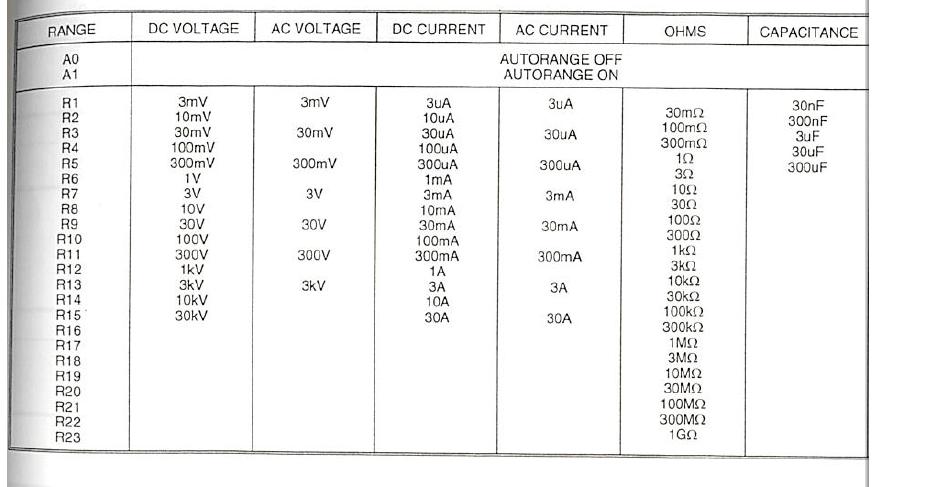
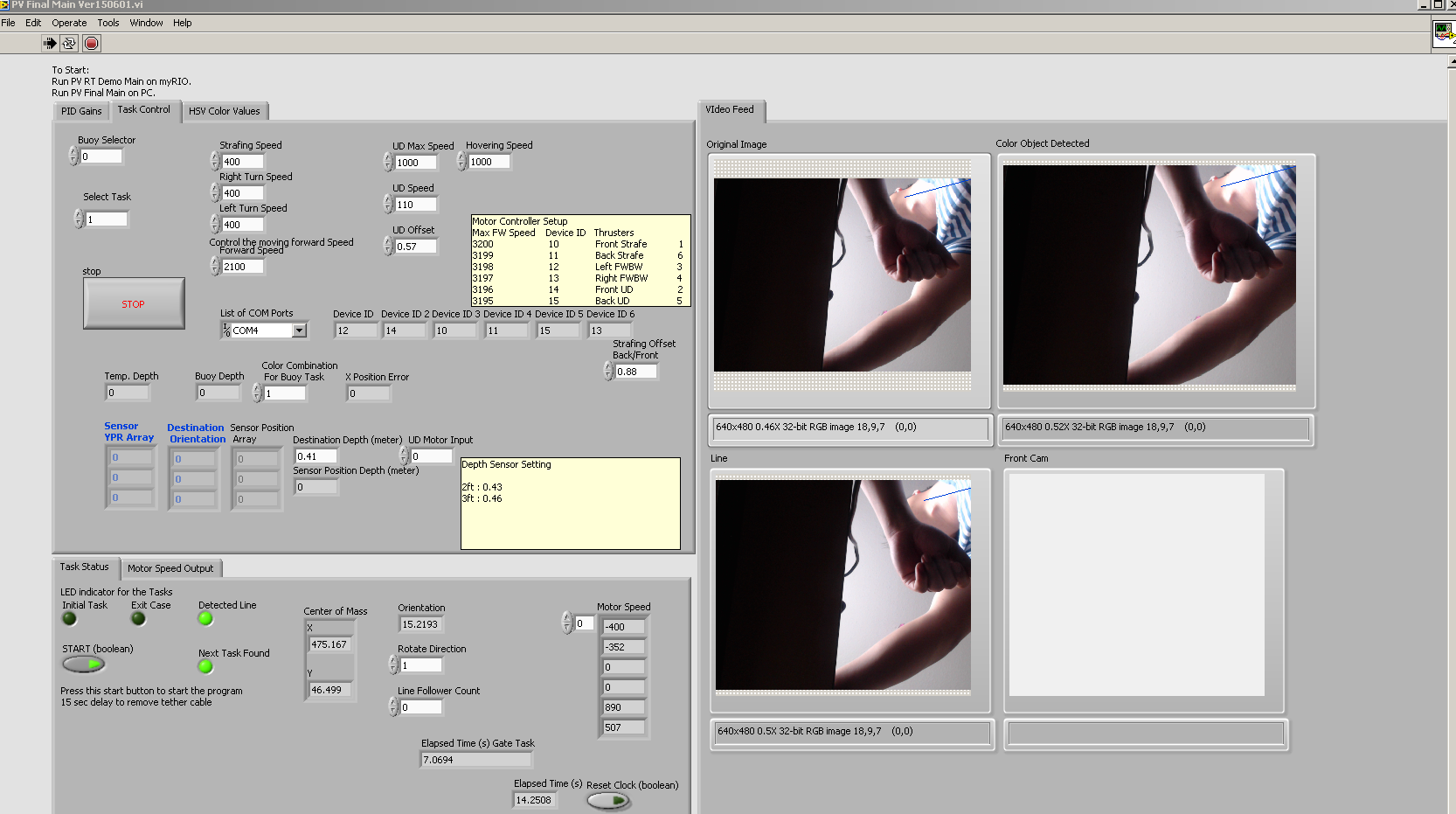
So I have this multimeter I need to make a driver for, and it has so many modes/scales of operation it will be a pain.
So that's what I'm working with, there are a lot of 'functions of measure', including the tension continues, alternating voltage, current DC current alternative, etc, there is more than what is shown in this picture, but functions are the first row in the table above.
Associated with each function is a set of ranges. GPIB codes for each range are on the left most column, and you can see what they are in the other columns.
To manage the functions of measure and the beach in this driver I have, I'll use 3 sub.vis:
The first sub.vi is very simple, consisting of a ring of unique menu, a number to string converter, then a concactenate string, shown in the first attachment. It sends the command of the unit function.
The third sub.vi is also quite simple, it sends the range control to the device. This is the sub.vi between the two that I need help.
What I want is to have a single control of the range , in the form of a ring of menu, and the 2nd sub.vi reformatted this menu ring. So what I need is to use a property node to set the line items in the ring menu to match with items included in the 6 columns above, so that if the function is chosen to be volts DC, the menu range ring will show 3mV 10mV, 30mV, 100mV, etc etc, but if the function is chosen to be alternating current the menu range ring show 3uA, 30uA, 300uA, etc etc.
The other tricky part of this is that the voltage and the current functions of the AC pass range controls (see how there is no range associated with orders R2, R4, R6, etc.).
That I'll probably be able to come up with something clever to treat (as simply double the value coming out of the ring and incrementing it with a + 1 on these functions to make them all odd), but for now I need help in the form line items in the menu ring.
Attachment 2 was my first attempt to simply edit the line items in the menu ring. Unfortunately the way it is put in place, he crams this whole string them in 1st command line, rather than separate. I don't know how to change one of the elements of the past that 1st menu ring.
Hope I explained quite well, make me know if I need to be clearer.
You use the wrong property. The property to use is 'Strings' and the entry is an array of strings.
-
Zoom to part of a graph of intensity?
I have a graph of the intensity at which the axis represents discrete channels. I want to be able to zoom the picture so that there are a whole number of displayed channels. The default behavior seems to be that when you the xoom, it is possible to see half the field strings. What I have is a situation where if the zoom on the y-axis range showed channel e.g. channel 28.1 to 22.7, that intrigue resize the y-axis of the range of 23 to 28. I would also like to ensure that a minimum of one channel displayed. I see no obvious and easy way to do it, but I would be wrong...
Thanks for any help,
Joe
You mention the intensity graph and table either. Because they are quite different, can you clarify what you actually?
Personally, I would use all digital controls to define the xmin, xmax. You can do the math and will check if necessary.
Alternatively, it is also an event "Scale range change", that you can use to change the beaches after the user has zoomed in.
-
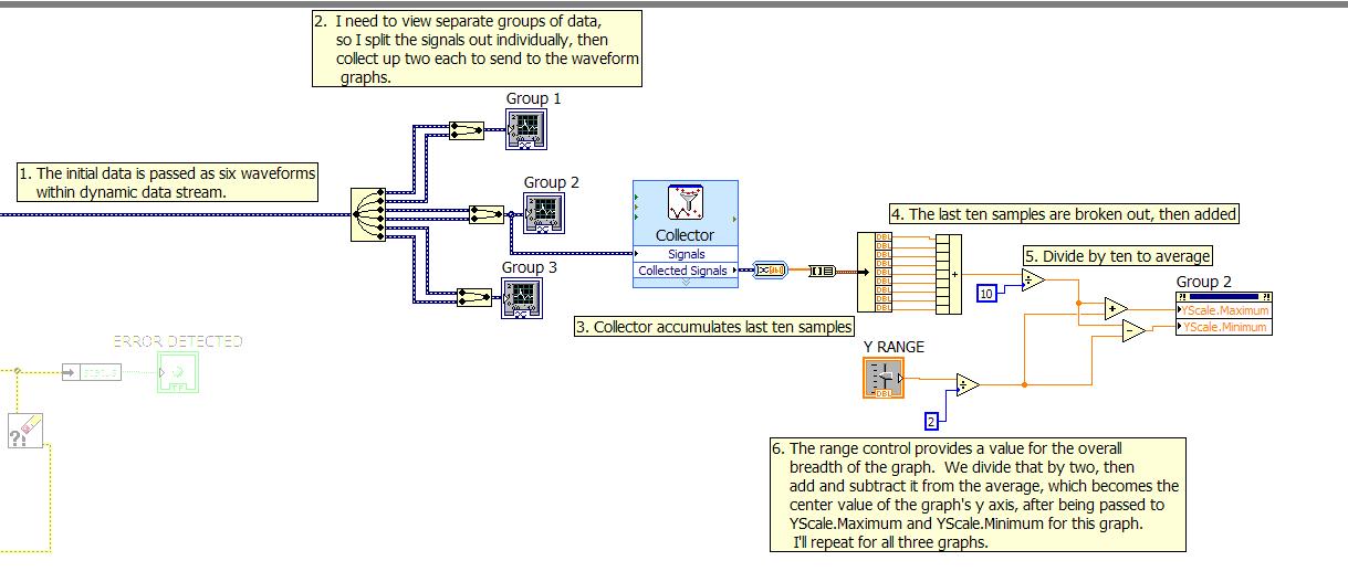
Calculation chart environment using collector, for an average
Hello
I was looking for a way to use a waveform graph, added the ability to set the width of the display of axis are all allowing a development of the chart track data, a little. It is because the self-centering of the graph feature is choppy and does not allow users to zoom in or zoom out on the ground (which my colleagues have asked).
It's basically my current solution posted here because I think that I finally got a right, but also because I know that you guys tell me: ten ways to do it better. :%^)
Note that the data here are slow; I think it would be really embarrassing if we looked at quickly changing data, although you could probably "Collect" more data and on average it all in the same way, to set the center of the axis y of the graph.
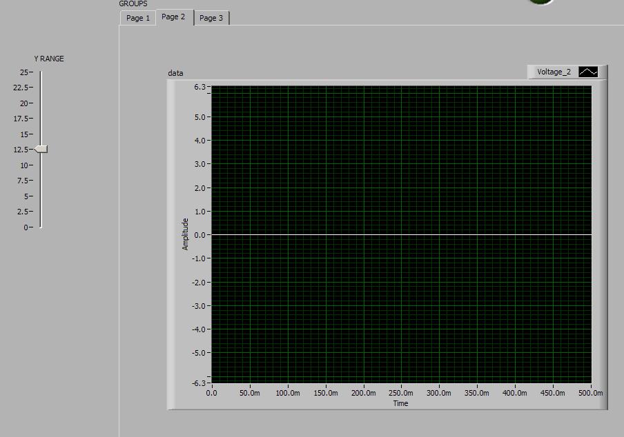
The front panel; I put in place the three graphs in a tab control. (Of course, there are no signals on the data acquisition module, when I did; but at least zero focuses on auto, and the range control works).
I guess I'm especially looking for your comments and I was wondering if I missed an obvious way to simplify this process.
Thank you
Danielle
Hey Danielle,
Given that it is a long-term test, are you interested displays all the data of your test or only the most recent game? The waveform table allows to memorize and display historical information because it has a buffer associated with it. From your code, it seems that this collector is just used to store information so that you can average the last few data points. The only thing I see standing in your way of simply with an average of your data is that it seems that you display two signals on the graph. So which signal you want to be centered? If you have a signal you want to reach on average to get the center of your chart, you may son of this signal in a convert from Dynamic Data VI express. When you put everything first down, a configuration window appears. You can then select ' 1 D array of scalars"as the type to convert. The output of this VI will then be an array of data points. You can then use the VI means to find the way to this table 1 d.
-
Change zoom on a chart programmatically?
I'm looking to add a few buttons or hotkeys to a chart control that allows you to zoom in or out a specific amount, or would zoom to adjust horizontally or vertically, but I can't find a way to change the zoom on a graph by programming (in LabWindows/CVI 9.0) - only features zoom/attributes I find are on-AutoScaling and other. Anyone know what kind of features, I would use if I wanted to change the current view on a chart control programmatically?
Hello
you will get a zoom setting the mode of scaling to the manual. For example,.
SetAxisScalingMode (panels, PANEL_GRAPH, VAL_BOTTOM_XAXIS, VAL_MANUAL, zoom_x_min, zoom_x_max);
adjust the x axis to the range given by zoom_x_min and zoom_x_max. It is the same for the vertical axis.
-
Scatter Chart with over 24 hours: confusing result
I have two columns of data. TIME is formatted as a date/time value with "Date: None, time: 19:07.» AVERAGE is formatted as a number. TIME contains values between 0:00 to 23:59. TIME is on the x-axis of my scatter graph, and the AVERAGE is on the y-axis.
When I create the graph XY scatter with these columns, the y-axis are mapping correctly, but axis x are not. Values of x-axis does not range from 0:00 to 23:59, but leave 08:05 on the left at 0:15 on the right. The values 0 and 08:05:15 not yet listed in my Chronicle of the TIME.
I suspect the formatting of date and time is the problem, but what is the solution (or work around)?
Thank you
view a sample of your table here for us to try would be helpful AND post a screenshot of what you have would also help you
-
Marking clips as Favorites IN timeline segments?
I know we can score selections of clips in the browser as Favorites. And then create a list of keywords / project amongst these selects 'F'
I find it very very slow.
I like to browse clips in the timeline. Just wheeled aligned segments I want and rock out to them until the next 'track' (arrow Alt Com upstairs). X'cuse, I know that we have more titles... but up out of the main plot. Once I get through a set of clips I delete all clips of scenario isn't the job offer and bring my selects down to the plot. Or lasso just copy all the upper clips and bring them to another calendar (project). And then start working with them.
I wonder if there is a way to do this more effectively? If I could choose "Favorites" in the story and translate them somehow to a new timeline project /... I know I can't.
So perhaps I wonder if there is a more effective way to make selects IN the timeline? Without the help of the browser? Something I have not come across but in the tutorials. Who all seem to promote the browser / Favorites method.
All ears and curiosity...
Ben
I would use the keyword Editor:

Entry/exit points in the desired clips mark then in the browser. With the R button, you can easily drag a range or even leaving the toll range WE.
Because a Section of Clip wanted in the first box to know all the shortcuts do you is now press 1 for each additional clip range control.
To summarize the process is simple, select a clip - drag a range - control 1.
Once this is done for all of the desired clips, select the event where clips and right click to create a new Smart Collection:

Name it something like:

Notice the icon is a flower looking thing which means that it is a Smart Collection.
Double-click the Clip Wanted event and the filter window appears.
Tell him to find only keywords then uncheck everything except wanted Clip Section.

The browser displays only items that you previously selected by using the beaches or in & Out points with a keyword of wanted music video Section when 1 control was entered.
Use Command-A to select all the clips and then press W to insert them into a cool timeline.
This is how I could tackle the job.
Al
-
update firmware 3.0.0f0 in 1900 to 3.5.0f0 and propellant myrio works not when use turn the engine.
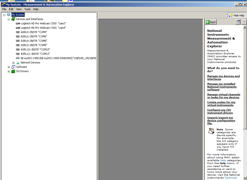
Dear Sir
I run this problem when I updated the firmware in myrio 1900 version 3.0 to 3.5. Before update, thrusters worked fine using the runtime engine, after update, propellers no longer exists. Any help will be much appreciated!
Thank you
Long
Hey Tao!
I'm glad to hear that your ports are now displayed in MAX. And I think it is a good idea to use the outputs analog on the myRIO. As long as you know the needs of the motor controller to order the right moves tension and a control loop in place, you should be good to go.
-
Waveform of Agilent DSO5054A read problem
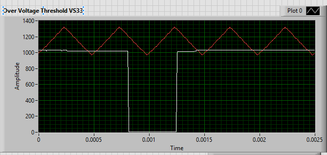
I'm reading signals oscilloscope with LabVIEW, but when I read the waveform, instead of the real tension, numbers ranging from 0 to 2000 ~ appears in LabVIEW VI. When I change the position of the wave on the oscilloscope, these figures are also changed. Please check the picture below. Are there settings I'm missing? Tensions on the scope are about 5 volts. Help, please.
Hello
You are using the wrong driver.
Try
http://sine.NI.com/apps/UTF8/niid_web_display.model_page?p_model_id=10028
Curt


Maybe you are looking for
-
How to revive the update of softBricked phone stagefright
I have a unlocked bootloader moto x XT1095 and after updating stagefright as my phone is blocked on the page "Bootloader unlocked warning." I can connect to the phone via fastboot. I want to give a stock image. When I run the command: fastboot flash
-
CS5.5 Master Collection downloaded, but Photoshop does not
Hello!I am currently using Windows 7 Ultimate on a PC and I downloaded the trial version of CS5.5 Master Collection from Adobe and Photoshop is the program I want to test... but for some reason any it is working properly. When I start Photoshop, it o
-
How to 'auto 100% size open' PS cc
Hello, I use CC PS for a while and until recently, I was able to open a batch of images (either by drag and drop or go to the menu file / open) to 100% of their size, whatever their size. My workflow works more efficiently when I can start at 100% as
-
Unable to sync files because the file name?
HI, I keep getting the message:"Unable to sync 'file name' because the file name is not valid. the characters |, ',?, , /,-, *, and: cannot be used in file names. "But I don't have any of these characters in the files that I am trying to sync.Help?
-
Adding metadata fields customized for full-text search
Hello guys,.Can someone help me on the underside.When I run the quick search content server. He search for data in dDocName, dDocTitle, dOriginalName and dDocFullText.I want my search will be performed on dDocName, dDocTitle,xCommentsand dDocFullText