Your output measures 0
Hello
I am trying to determine the frequency of an analog signal (pulse tachometer) in order to calculate the number of LAPS and integrate it into a LabVIEW program. I tried to write a "dummy" program before I it implement the complete system of LabVIEW in my workplace, but my dummy program will not work.
First of all I tried to do with the Measurement & Automation Explorer and used 'measures of tone' VI, and it worked like a charm. However, when I tried to put in place without the MAX (i.e., task > sample clock > start measurements > read measurements > your VI measures), I get a result of frequency 0. Joint are my MAX (tach than works.vi) file that does not work and my file which does not (tachometer File.vi).
I use a cDAQ-9174 and a NI 9203 as an analog input card.
If anyone of you could help, that would be most appreciated. Thank you!
Tags: NI Software
Similar Questions
-
I used successfully the packer online blackbery which generated a *.bar file. When I try to download this file as a liberation. I get an error saying "Please download valid zip containing your bundles of liberation." BlackBerry really provides no instructions after this step. Any body know what I can do?
Hi bootini, welcome to the forums!
For submission to the BlackBerry World, you can download your BAR file in a zip (zip the bar).
I hope that it has adequately addressed your concern.
-
half-wave rectified filter circuit/oscilloscope measurement
Hello everyone, I hope I can get help on this fundamental issue, I'll have. University online, with which I will not help me, so I hope that I can quickly get assistance here.
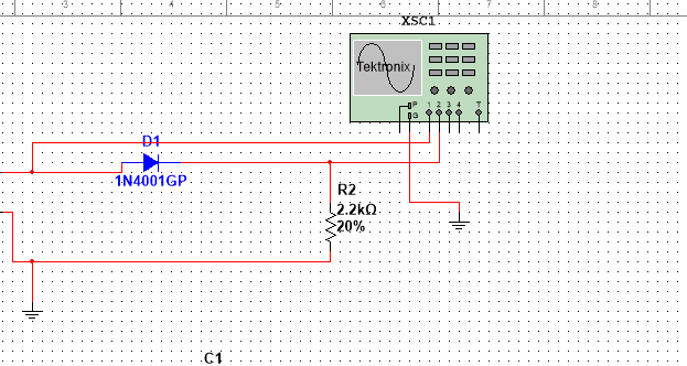
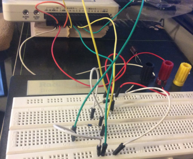
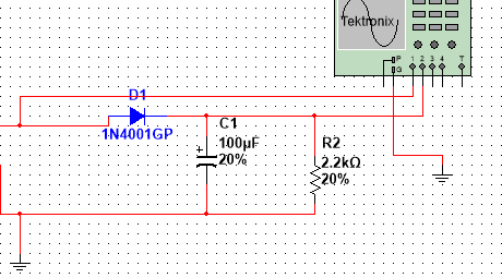
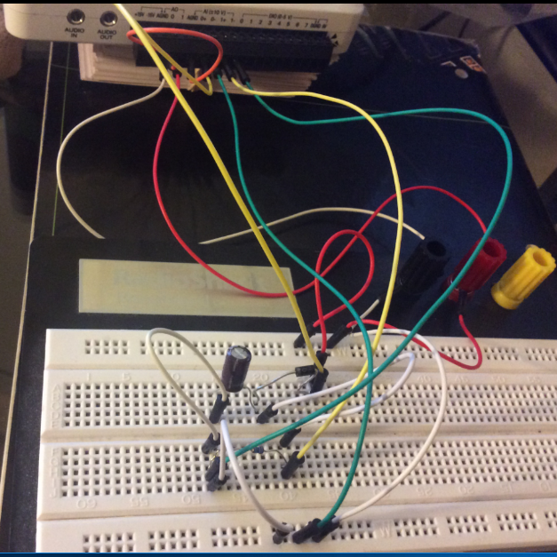
I have the myDAQ NOR, I have to build half rectified filter circuit with a resistance 2.2kOhm, I also use the multi-sim to confirm the measures of waveform. Everything goes well on Labview multisims Tektronix Oscilloscope compared to before I connect a capacitor 100uF my comparison heres:
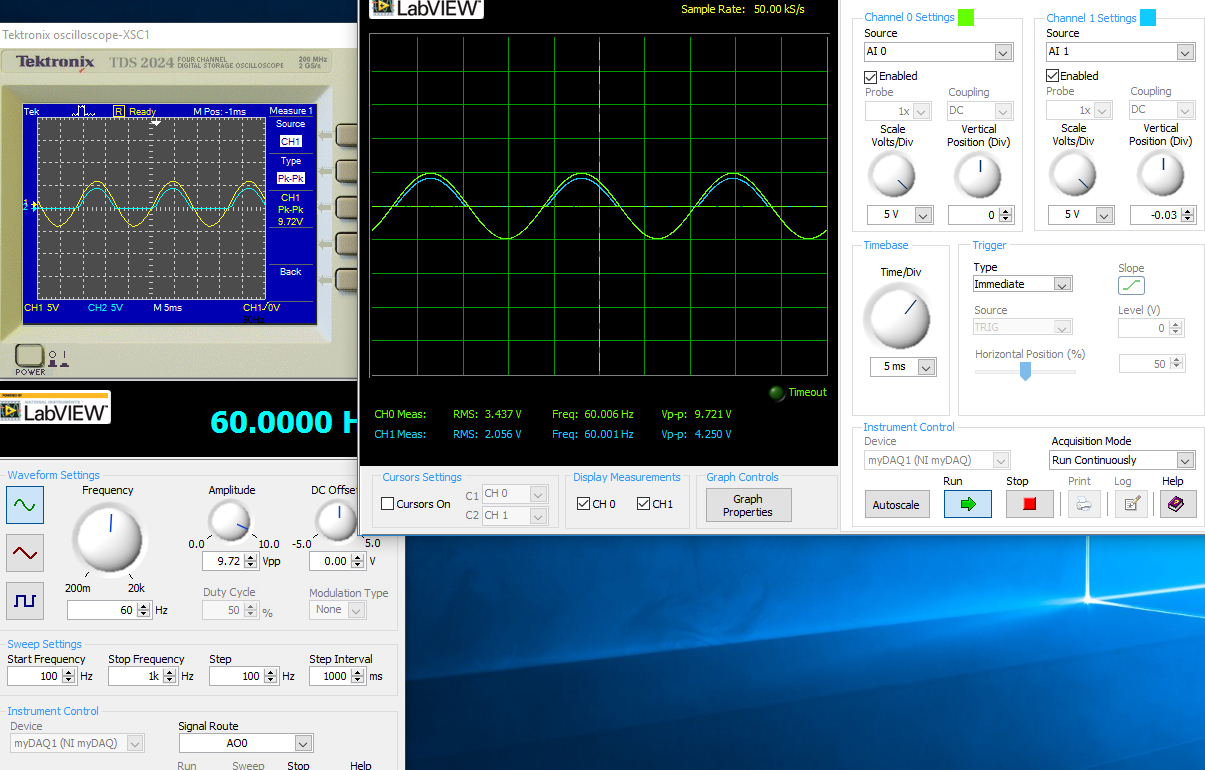
The model is just the Diode with a series resistance 2.2kOhm, I'm not sure if the analog inputs to the LabView Oscilloscope are configured correctly this is the air I get:
This satifies my simple comparison on the Multisim circuit, since I came here for a few hours to play with probes analog input, I know that something is wrong out of these measures, I get.
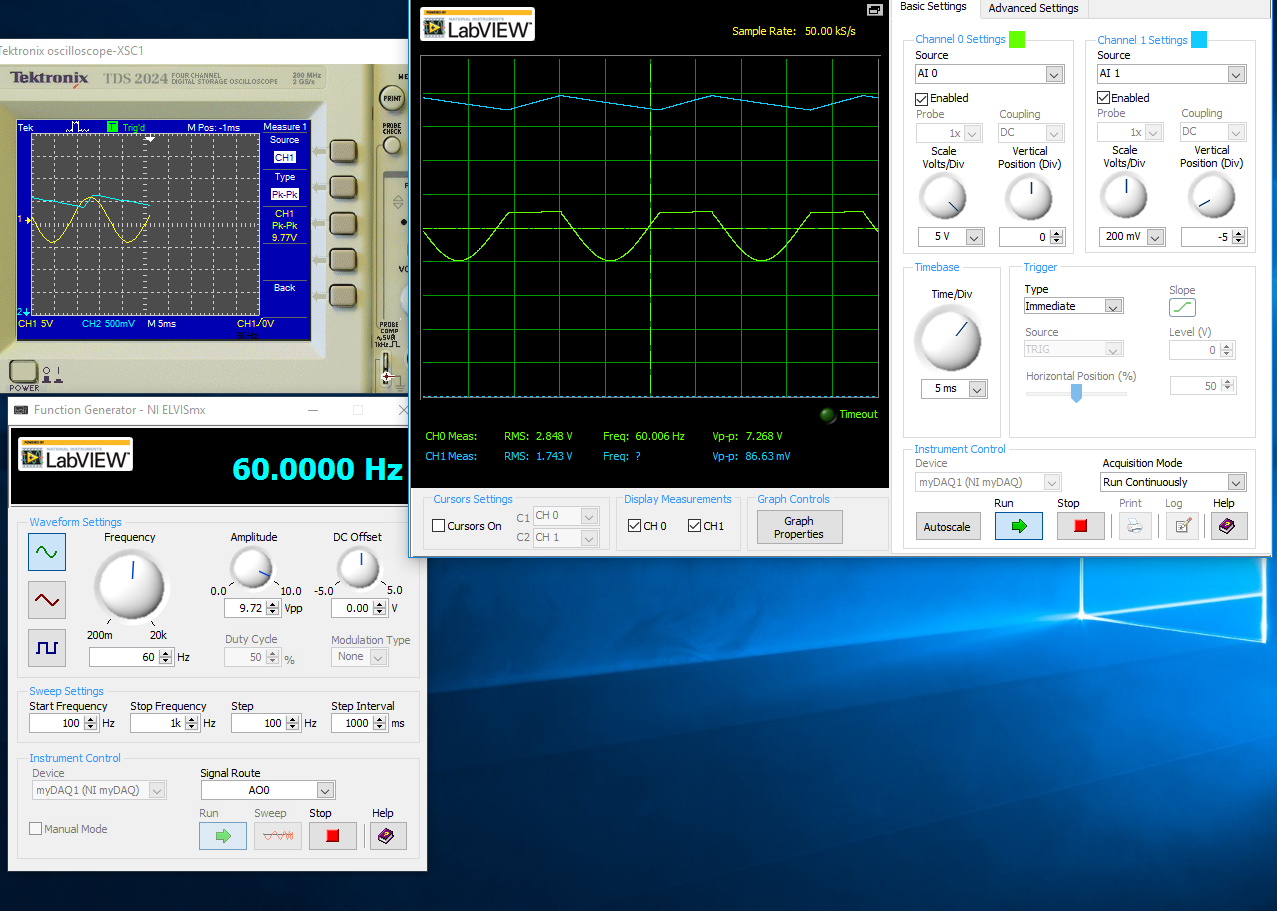
With a capacitor 100uF in parallel:
I think the question is how I inputs analog and STILL plugged, I'm not sure that this is where I would really like some help or any type of assistance. Once I get this set up right, I'll be able to take measures for the frequency, load DC, P - P Ripple voltage ripple and then move to a full-wave rectified circuit. I just started a course and received the myDAQ.
Henrik_Volkers wrote:
Compare it with the current specification of output of your myDAQ

Here is a link to the specification: http://www.ni.com/pdf/manuals/373061f.pdf
Henrik hit it on the head. The myDAQ can, at most, out 2mA with analog output. So, with a 2.2kOhm charge, which puts you in 4.4V without the diode. The led will also require an amount of current. According to my estimates, subject of 1mA (your pic is ~2.5V, divide by the 2.2kOhm to get ~ 1mA). You will see only that on the positive side of the sine wave as the diode blocks all the negative side.
The lesson here is to make sure that your outputs have enough power to do what you want. You can go to get a simple op-amp from digikey and use a follower of tension for editing the current upward. You will probably need another power supply or two (+ 12V and - 12V) to power op-amp.
-
Measurement time 4132 SMU is too high
Hello
I use PXI - 4132 DC EMS to perform some DC measurements at high speed. I just took a 1 K Ohms resistance, forced 1mA and measure 1V. I have this done configuration and code completed. I get the correct measurements. But my problem is with the measurement time. The total duration is about 45ms to complete installation and measurement, with the exception of the 'initialize and close '.
I checked the time at every step and I noticed that the maximum duration is taken during the "voltage reading. Out of the total 45ms, it takes about 34ms just for a measure. It's just a VI "Ukraine power measure" takes about 34ms, which is ridiculous compared to the Kiethleys. I tried to vary the time of "openness" and turn off the 'Auto Zero'. But the measurement time is still high. Can someone help me and let me know what is the best time of the measurement obtained with 413 x series SME?
Thank you!
Hey Phx_tech,
The amount you reduce your delay source depends very much your HAD and how regular you have to your level of tension until you start taking your measurements. If your Instrument is reactive, you can see discount gas and unintentional ringing during the transition from your output level and therefore would allow enough break-in before taking your measurement. The best thing to do is to experiment with different delays of source and see how much delay need you to get a consistent and reproducible measure. If you have a scope that is available, it will also show you the step response of the SMU with your Instrument. If your first reading is higher than your other readings, that this could very well be a problem with not enough time settling. What kind of DUT Testez_ you?
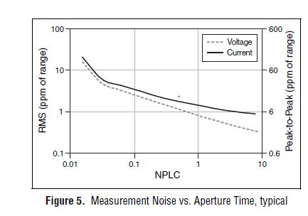
From page 4 of the specification, you can see that 1 PLC, we can expect about 1 ppm RMS noise of the range to 1 PLC. This means in the range 10 au our measurement noise would be 10 pA RMS or 60 pA pk - pk. However, your DUT + cables will pick up the extra noise and you should consider using wires of twisted shield pair to reduce noise picked up in your system. The shield can be terminated at the mass of the chassis on the side EMS of the cable to help reduce noise appearing in your measurement.
Let us know what you find after experimenting with you HAD.
Thank you!
Brandon G
-
My computer guard lost its audio, no device installed usual message, only started doing it in the last 6 weeks, can only get back using a previous restore point, went again this afternoon.
If your computer has problems play a sound, try using the Audio playback problems resolution to solve the problem. For measures and additional information, see o ink below.
Open the troubleshooting of Audio playback
http://Windows.Microsoft.com/en-us/Windows7/open-the-playing-audio-troubleshooterOpen
http://www.Microsoft.com/Windows/compatibility/Windows-7/en-us/default.aspx?type=hardware
http://Windows.Microsoft.com/en-us/Windows7/tips-for-fixing-common-sound-problems
You have a fluorescent lamp next to your computer which could be emitting a rf? This could interfere with the microphone.
In Windows 7
Click Start > Control Panel
Click on hardware and sound
Under sound, click on manage audio devices
Under playback (tab)
Choose speakers you have in your output device
Click Properties >
Click levels (tab)
check if the value is 100% >
GoTo Enhancments > select Loudness balancing
Apply and OK
Should be much stronger now...
For enhancment bit,.
and if you have HD realtek soundmanager (R2.37) in your control panel
Try a classic Equalizer setting
-
Display of the output on Satellite L20 and L100 options
I work in a school where a large part of teachers use projectors to display work for children.
On L10 laptops when you right click on the desktop it allows you to choose your output (e.g. monitor/computer laptop/double screen etc.)
How can I get this option on the L20/100?
The combination of keys 'Function f5' works occasionally and if you select a second monitor and check the 'extend the desktop on the screen"(or something in that sense) you get only the desktop, no icons no apps... apparently a patch exists... any help?
Hello
The extended desktop option expands the laptop to the external monitor screen.
You will have all the icons on the second monitor!You can move the window of the Explorer open IE or the Word document for the second monitor.
This allows you to use both names without switching.If you want to have the same display on monitor internal and external, you must clone the laptop screen.
The FN + F5 function key allows you to do. -
Outputs digital synchronized DAQmx
Hey, I am trying to send two synchronized digital signals of a PCIe-6420 device.
Here is my code:
DAQmx configure clock
DAQmxErrChk (DAQmxCreateTask ("Clk", & taskHandleFRQ));
DAQmxErrChk (DAQmxCreateCOPulseChanFreq(taskHandleFRQ,"Dev1/freqout","",DAQmx_Val_Hz,DAQmx_Val_Low,0,ManchSampClkFreq,0.5));DAQmx digital output configuration
DAQmxErrChk (DAQmxCreateTask ("Harmony", & taskHandleHarmony));
DAQmxErrChk (DAQmxCreateDOChan(taskHandleHarmony,channel2,"",DAQmx_Val_ChanPerLine));
DAQmxErrChk (DAQmxCfgSampClkTiming(taskHandleHarmony,"/Dev1/PFI14",ManchSampClkFreq,DAQmx_Val_Rising,DAQmx_Val_ContSamps,sendCount));DAQmxErrChk (DAQmxCreateTask ("DOchan", & taskHandle));
DAQmxErrChk (DAQmxCreateDOChan(taskHandle,channel,"",DAQmx_Val_ChanPerLine));
DAQmxErrChk (DAQmxCfgSampClkTiming(taskHandle,"/Dev1/PFI14",ManchSampClkFreq,DAQmx_Val_Rising,DAQmx_Val_ContSamps,sendCount));DAQmx Configure similar output
DAQmxErrChk (DAQmxCreateTask ("AOchan", & taskHandle));
DAQmxErrChk (DAQmxCreateAOVoltageChan(taskHandle,channel,"",0.0,10.0,DAQmx_Val_Volts,));
DAQmxErrChk (DAQmxCfgSampClkTiming(taskHandle,"/Dev1/PFI14",ManchSampClkFreq,DAQmx_Val_Rising,DAQmx_Val_ContSamps,sendCount));DAQmx write code
DAQmxErrChk (DAQmxWriteDigitalLines(taskHandleHarmony,sendCount,0,10,DAQmx_Val_GroupByChannel,SendManchHarmony,,));
DAQmxErrChk (DAQmxWriteDigitalLines(taskHandle,sendCount,0,10,DAQmx_Val_GroupByChannel,SendManchData,,));
DAQmxErrChk (DAQmxWriteAnalogF64(taskHandle,sendCount,0,10.0,DAQmx_Val_GroupByChannel,SendManchAnalog,,));Starting code DAQmx
DAQmxErrChk (DAQmxStartTask (taskHandleHarmony));
DAQmxErrChk (DAQmxStartTask (taskHandleFRQ));
DAQmxErrChk (DAQmxStartTask (taskHandle));Only problem, is that I get "error DAQmx: NI service platform: the specified resource is reserved." messages.
The name of the task associated with the error is DOchan: aka: taskHandle. If I rearrange the code such as taskHandler events occure before the equivelents to taskHandlerHarmony, then errors are associated with harmony: aka taskHandleHarmony instead.
That I am I doing wrong and how should outputs digital syncornized be implimented instead?
Think of the fifo in a block of memory that is the same width as the digital port where each bit corresponds to a single digital line. The samples are transferred from this FIFO to the port in written all over port (there is some logical activation, so only those lines that are configured in your output task are actually updated each sample clock). DAQmx will combine the data you write for if make sure that the correct data at the scale of the port gets written in the FIFO. DAQmx for this by looking at the configuration of the group 'line' in DAQmx create DO canal and the "dataLayout" specified for the function DAQmxWriteDigitalLines.
You have two lines you have set on DAQmx_Val_ChanPerLine. This means that when you call DAQmxWriteDigitalLines, it will be expected to see enough data to two data channels. The way in which these data are specified is configured by the dataLayout. By specifying DAQmx_Val_GroupByChannel, you say DAQmx data for each channel to be grouped. You should do these groupings in the same order that you specify your channels.
So consider the following:
DAQmxErrChk (DAQmxCreateTask ("DOTask", & taskHandleDOTask));
DAQmxErrChk (DAQmxCreateDOChan (taskHandleDOTask, "Dev1/port0/$line0", "", DAQmx_Val_ChanPerLine));
DAQmxErrChk (DAQmxCreateDOChan (taskHandleDOTask, "line1/port0/Dev1", "", DAQmx_Val_ChanPerLine));
DAQmxErrChk (DAQmxCfgSampClkTiming(taskHandleDOTask,"/Dev1/PFI14",ManchSampClkFreq,DAQmx_Val_Rising,DAQmx_Val_ContSamps,sendCount));We will alternate digital high/low between our two lines (we will write the 10 values of each line), with the exception of this last point, where we will write two lines high
The data should be written in the corresponding line bit position (if I remember correctly)which means you want to manipulate the lsb for the 0 line, and line 1 manipulate you the 2nd lsb.
Int32 [10] line0Data = {1,0,1,0,1,0,1,0,1,1}
Int32 [10] line1Data = {0,2,0,2,0,2,0,2,0,2}
Int32 dataArrayByChannel [20];
Int32 dataArrayInterleaved [20];
for (int32 i = 0; i)< 10;="">
{
Group data through
dataArrayByChannel [i] = line0Data [i];
dataArrayByChanne [i + 10] = line1Data [i];
Group the data by scanning
dataArrayInterleaved [i * 2] = line0Data [i];
dataArrayInterleaved [i * 2 + 1] = line1Data [i];
}
We can write data in one of the formats that we just built, but we must provide DAQmx with the correct dataLayout.
DAQmxErrChk (DAQmxWriteDigitalU32 (taskHandleDOTask, sendCount, 0, 10, DAQmx_Val_GroupByScanNumber, dataArrayInterleaved, NULL, NULL));
Alternatively, we could write per channel. If we chose, it would look like this (you wouldn't do both).
DAQmxErrChk (DAQmxWriteDigitalU32 (taskHandleDOTask, sendCount, 0, 10, DAQmx_Val_GroupByChannel, dataArrayByChannel, NULL, NULL));
DAQmxErrChk (DAQmxStartTask (taskHandleDOTask));
In both cases, DAQmx must write the following data to the FIFO:
x 1
x 2
x 1
x 2
x 1
x 2
x 1
x 2
x 1
x 3
In this way, the data written to each line are combined by DAQmx then written to the FIFO. Allows you to specify the data for each channel individually.
It was quite long, but I hope it will answer your question. If I was not clear, please let me know.
Dan
-
Hi guys,.
Im a software using advanced LabVIEW PID and hourly programming. But as my gain change, the output does not accordingly with my gain. For example:
Error = 10
Gain = 10
Output = 100
Then
Gain = 0, 01
Output = 100 supposed to be output = 1
Looks like transfer smoothly? I couldn't tell.
Yo have any idea why? The VI of "PID Gain schedule example" change accordingly with the error output. But mine is not. I hope you guys could help

Not the Gain annex vi does not change your output according to the entry it will select all of the gains that you want to use. In a certain type of profiles, we will have to use a different set of earnings, so in these cases, you can have a different set of gains and which apply accordingly. For your business simple PID must be suffucient.
-
Output of MatlabScript in the matter of the loop
Hello everyone, but long time reader first time poster, and I was wondering if I could get help to a little problem here, or... Well, more like a question and not a problem.
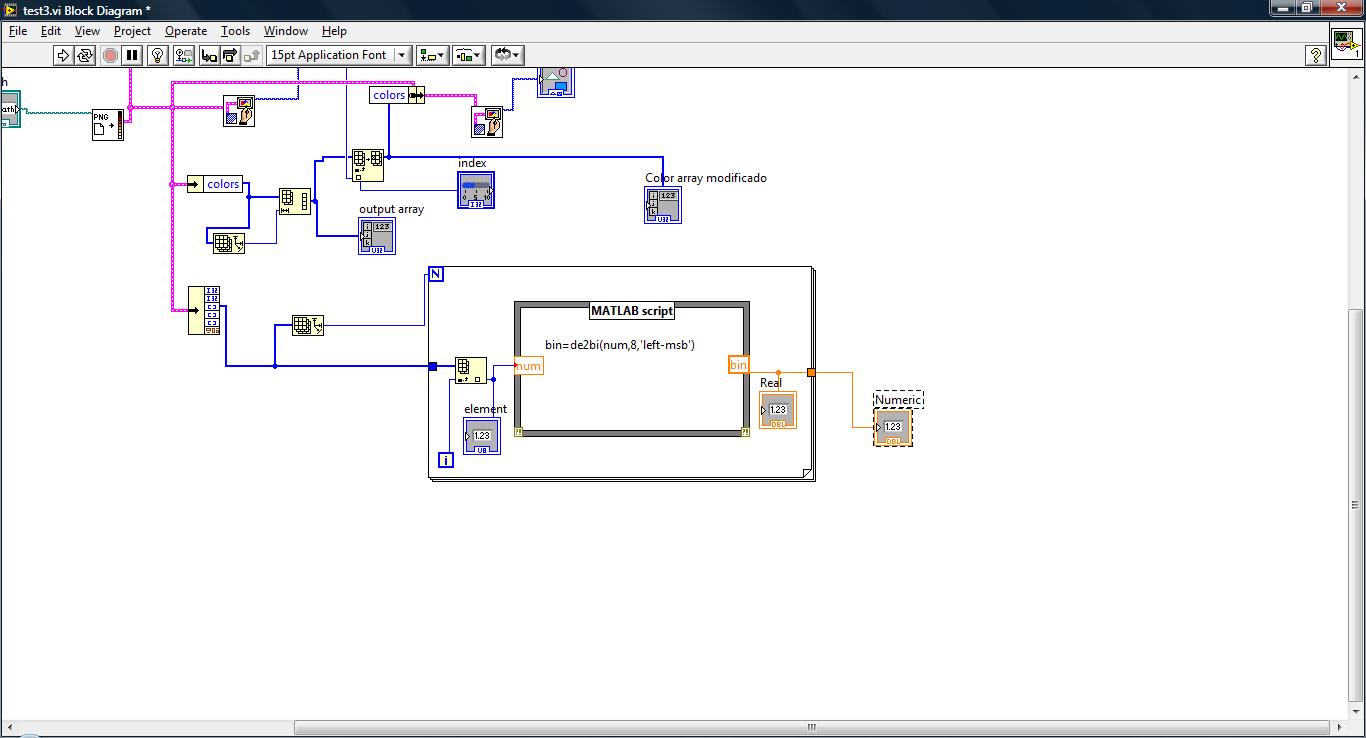
I don't download the .vi because I don't think it will be necessary, in addition, ignore the rest of the image (I just play with image processing like I taught him) and go to the location of the matlab script.
My goal is to represent the image (taken from image data) bit and in the end, it must look like to... a table of 8 columns and all the lines she might need (can't see all of the lines of course) so it will look like a matrix.
For example, it should look a bit like this on the user Panel
| 1. 0 | 1. 1. 0 | 1. 0 | 1. (first 8 bit value)| 1. 0 | 1. 1. 1. 0 | 1. 0 | (8-bit second value)
etc...
So for that, I use the matlab de2bi function and the release of this part is where my problem is, im putting out 8 columns representing each number comes from the image and well, im confused as to what is going out of the matlab function and the loop, as you can see in the picture I have uploaded, I put a flag in the output of 'bin '. , was automatically called Real, inside the loop and the other digital, outdoors, also, I disabled the index of the tunnel in this output. (if I activate the index, it comes out as a table)
I thought that Real and Numeric to be showing the same thing, but when I run it, which doesn't seem to be the case, you Real shows the 1 and 0 (I guess it shows the 8 bits because it shows figures but I saw in the matlab command window and there are 8 bits stored in 'bin') and digital remains just at 0 its almost as if nothing were happening out of the loop, and because I'm not sure what it is falling I can't really find a way to show the bits as in the example, I said before.
Read the help of de2bi, it is said that his exit is a matrix if the input is a vector, but I don't think it's a vector since due to the loop, it takes value by value, then it must go to the default (in binary) value too...
Thanks for the help in advance, in addition, whether something else to better understand my problem please say so and I will do my best to make it easier to understand.
I don't know why you're so obsessed on matlab, LabVIEW can do all this much simpler directly. Here's a possible solution. (LabVIEW 8.5. For other possible outputs you could reverse the Boolean array, so modify them.).

(Your main mistake under matlab is that your output of matlab is defined as a scalar value, then it should be a vector. Your tunnel to exit of the matlab node has the wrong data type.)
-
DC motor of control using the analog output of DAQ 6008
Hello
Since the 6008 DAQ implements not good PWM, can I control the speed of the DC motor using outputs analog, protected by amplifiers?
This will damage my DAQ?
Ok. The engines will be quite low.
Consider using an LM317 as the "amplifier". Add one or two diodes protection. Connect the AO to the terminal of the regulator with a resistance setting to land. Your output voltage can go down to 1.25 V and up to minutes (battery-2 V, Vaomax-1,25 V). If you have a battery of 12 V and a 12 V, the maximum speed of the motor engine will be slightly lower than the nominal speed full. The minimum voltage the motor probably will not work. The regulator has a built in protection against overcurrent and overheating. It's the motor controller cheaper you can do and works very well.
If you need to reverse the engines, things get complicated a bit more. You can use a DPDT relay or a transistor H-bridge.
Lynn
-
Hello
I have problems with my pid in the sense that it displays only 2 values(min_and_max).i have tried different gains and yet it will not work properly.can someone help me please? the process I'm tring to control is an oven, and I use NEITHER 6024E and CSC-2345. (I also tried without the dt s, using a simple wait in the while loop, but it is not influence it)
Your output range is tiny (0 to 0.02). In the meantime your comments seems to be on a much larger scale. Your P gain being 20, any error (difference between setpoint and variable processes) greater than 0.001 will be enough to drive the full output or full out (20 * 0.001 = 0.02). You need either a larger output range (and then scale before you send the output to the DAQ hardware) or much smaller gains (which could result in the loss of some mathematical precision).
-
acquire the voltage output of a channel of analog output current
I'm controlling a HV configuration rather sensitive analog output voltages. Is there an easy way to read the voltage level which is currently awarded by an analog output?
Hello
If you set your subVIs different voltages, you can be sure that the voltage you set in these screws are similar to tensions, you have to your output PIN. For example, you could write the value you give to the output in a variable and read this variable in you main VI.
Kind regards
Peter
-
How to determine the number of highlight ' to write ' for DAQmx generate analog output?
On the configuration of the stage for DAQmx generate analog output, there is a field "value to write. I can't find any explanation for what it is, how it determines the value to enter, nor what he writes. I am trying to go through the tutorials and it cling.
Someone would give an explanation?
Hello
To write value specifies the value to write in the channels, lines or ports selected in string parameters. In other words, this value will be the value of your DC output (for example if you enter 5, your output will be 5V). To get information on different fields in SignalExpress, access help"context-sensitive help. A pane will appear in your work environment that displays the coordinates of the field when you place your pointer over them.
For new users of SignalExpress:
Generation of DC signals with NI DAQmx devices: step in the DAQmx build, select 1 sample (on request) in the generation Mode dropdown. You can select a programmatic input to generate, or you can remove the check mark from the check box use programmatic input and specify a value for generating in the field of value to write . NOR-DAQmx help also provides additional information about the data generation.
Best regards
M Ali
Technical sales engineer
National Instruments
-
what you get when the sequence is used as output, tension or strain?
Mr President
I m using scxi1520 with watchkeeping configuration, by setting the entry like strain, what value I get is not strain that I calculated analytically. someone told me that what value you get by that is tension not strain, I calculate strain from here by the formula.
I don't get that this is strain or tension.
I have an extensometer of 120 ohms with two gage factor. Please clear my doubt I have with this as soon as possible.
Think about the data being represented in different ways. Your contribution is the strain. The strain gauge that converts resistance. The bridge becomes the resistance a tension. An amplifier multiplies by a constant tension and perhaps subtracts an offset. The analog digital converter changes the analog voltage to a sequence of tension with two possible values (0 to 5 V) at every moment in the (digital) sequence. The computer processes these digital tensions as numbers that have a strong correlation with the amplitude of the analog voltage.
But you try to measure the deformation, so you don't really care voltage analog or digital, except that need to know the relationship between them and the original strain.
Your tension measures data acquisition system. You must provide conversion from units of the strain through calibration.
Lynn
-
How do detect you if a person spying on your computer. How do you keep it
I have 2 pc. You can detect if 2 pc spy remotely on pc1. If so how do you keep it
Hi Traci,
I can't provide technical and tactical spy, hacking methods, or how to use malware to infect a computer with programs or also in a forum dedicated to protection against such things - I don't know if it would be a violatiion of the forum (more likely) COC, but it would be a violation of my ethical principles. There are countless methods. I will go this far just to give you an idea (and this is more or less a "sanctioned" method used by employers and parents to monitor the activity of employees or children and not the most sophisticated hacking methods)- and I'm not recommending or suggesting this program (I almost never recommend paid software when I can usually find free options that work almost as well and I don't know anything about and) just a quick did search to find one to use as an example), but just use it as an example of what can be installed, see: http://spysoftware.com/spyagent.html which is even more powerful with a direct administrative access to your computer.
If someone has administrative access to your computer, then it is extraordinarily difficult for anyone to detect it or prevent espionage (if done correctly). I don't know yet I could do (detect-not necessarily in place - according to the way it was done - well well, I might be able to do it if I knew it was going on and worked on the problem until I found the culprit, but that could take days or more and some very sophisticated and software procedures may be special) , and I'm very concerned about security. With direct access, it is just too easy to do it in a way that will be almost impossible to detect. Depending on your operating system and how much effort you want to put into it, there are steps to take to minimize the problem. If you are allowed to block the person who has access, it becomes even better. If the question concerns only protect against certain types of espionage (as opposed to any type), then it becomes easier again - but even in this case, there are some guarantees if they have the same level of access (or access) and direct access to your computer.
In some cases, using spyware on yourself (that you install to spy on your own computer) can detect other spyware activity or activities (I used successfully this particular thing before) - but there is no guarantee (as it can potentially be bypassed if anyone knows there or by using techniques that do not trigger to detect activity) - but it has sometimes proved effective (note it does not - it CAN help to) detect if things and knowing that and possibly how it is done you can take improved or maybe even effective preventive measures until the inability to spy is detected and then they would just adapt to overcome or escape from your preventive measures).
The honest answer is that, to get the protection you want, you need to block to have this level of access to your computer (after a format and a clean install in order to eliminate what they've already done). Once they are blocked, then the methods to use normally appear more ordinary procedures, if you knew what to look for.
If you allow me, why you allow him to have access to your computer? If you are trying to overcome parental control, then I will not help you and you should reconsider what you're trying to do (and even if it works, they will know that you have done and can eventually impose restrictions that greatly limit your activities and who are far worse than the spy was in the first place - that is how I would react as a parent). If you try to overcome the employer monitoring, efforts to work around could have consequences job that you do not want to happen. If it isn't, then why are you allowing this access and what are the rules for your ability to restrict this access somehow? Also, is there a specific business type that you are specifically concerned about or is this activity?
As Robert has said, it is better, if this is done in a separate thread, but if you want me to participate, at least after the link to this new thread here as an answer I cannot not otherwise it exists and it will almost certainly miss myself (although others can certainly help you as well).
I hope this helps.
Good luck!
PS Instead of creating another post for your other question, see the following for an explanation of the features of keylogger: http://en.wikipedia.org/wiki/Hardware_keylogger (NOTE: it's hardware, not software since you said "peripheral"). Keylogging can be done using software as well. For more information about keylogging devices and make sure that not all of these sites are safe (as with any general research), see the general Bing following research: http://www.bing.com/search?q=keylogger+device&PC=BB07&QS=n&first=11&FORM=PERE.
Maybe you are looking for
-
AMD high definition Audio Device not Plugged In (HP Pavilion dv6-6b09sa)
I just started my laptop HP Pavilion dv6-6b09sa (running on Windows 7) to find that the sound icon is a red cross next to him and he claims that "no speakers or headphones are connected. In Control Panel, it says that the AMD high definition Audio De
-
Firefox does not open my email account
Firefox does not open my Yahoo email account, I open it with another browser, Internet Explorer or Chrome, but with Firefox not more! This has happened Each time Firefox opened is 2 months ago
-
Satellite P100 - time clock keeps changing
The clock on my Satellite P100 continues to change (running Win XP MCE) randomly during the day while it is running. When I start the PC in the morning, clock's time similar to when I turned off the day before. I use my PC in my office connected to t
-
Can't put the computer on standby or into hibernation.
I get a message box stating that: update Microsoft.Net Framework v1.43222 is my computer can't spend in standby mode or Hibernate mode. In "Add and remove" I can't see anywhere to remove an update. Around the same time, this problem appeared from now
-
Cannot install mouse__ and wireless keyboard
I have a dell dimension 2400 running xp. I'm putting a new keyboard and mouse on it. I have a logitech wireless keyboard and mouse. When I try to install it I got an error box that appears and indicates the software> You are installing for this ha