9237
I try to connect to the strain gauge and load the samples at one per second, but I'm too much points.
I looked at other examples, but I can not simply slow the pace.
I use a grid cDAQ-9172 and 9215 input voltage and a 9237 strain gauge module.
Each module has 2 channels.
It turns into one of those LabView issues that take longer than expected.
Can someone please look at the vi attached and see where I am going wrong.
The entrance of pricing does not appear to be much affect.
At what rate should I set the maximum task I use continuous samples.
Thanks for any help,
Stagsden
You see additional samples because you are not acquiring data to 1 sample/s but rather 1 612 samples/s. The NI 9237 is a set of discrete sampling frequency (50 kHz / 1.31). Your task is to compel the sampling until the next valid value, 1 612 in your case. This constraint is normal but with devices sigma delta step to the next valid value is larger than other materials. Sampling rate limits are listed in the NI 9237 specifications in the frequency range "Understanding NI 9237 debits" section and the data in the section "Specification".
You can determine your actual sampling frequency by questioning the sampling (not at the MAX).
Tags: NI Hardware
Similar Questions
-
Hello
I'm new in Labview. I have a 9076 Compactrio, connected with a 9237 module and a set of scales. I have already connected with success (NI 9237 Getting Started.vi is connected and functional without problem), but when I try to compile the example: .vi NI 9237 Getting Started (host) some son display the error. I have attached the image.
How can I solved it, in order to compile the example (host)?
Thanks in advance.
You must configure the FPGA open reference to point to the bitfile you generated for the FPGA.
-
NEITHER 9237 external excitement - VeriStand 2013 SP1
The voltage recommended for my pressure is + 10 VDC sensors. I prefer to use external excitation according to the NI 9237 manual, total power to the module is limited to 150 mW, which in my case is "four bridges complete 350 ohm at 3.3 V. (I'll use pressure transducers (4) 350 ohm full bridge). I use scanning for EtherCat engine and the NI 9237 in a chassis 9144 OR connected to a cRIO-9081. For troubleshooting, I have two transducers on a pressure calibrator and another RJ50 connection a NI 9949 escape. If I select "External excitement" and have my power supply of 10 V connected to the bass + EX, EX-connecteur, I get an invalid value for my pressure sensor. It is after the scaling of the calibration value. The gross value is also incorrect. If I let the value "External excitement" but shoot the EX +, EX-connecteur, the EX +, EX-tension (pins 6 & 7) will go to 4.735 V and I'll get a CORRECT pressure reading. If I select an internal 3.3V excitement, I'll get a statement of the correct pressure, but I am a little concerned about the resolution that recommended excitement is + 10 VDC for the pressure transducers. My question is: Why can't I use the external excitement? I have another application with a chassis PXI and EtherCAT and it works OK. I also tried to place a NI 9237 module in the chassis cRIO-9081 and get the same invalid value that I describe above.
You have the latest version of the scanning engine and EtherCAT custom device? On the community page for this custom device, the last listed specifically done bug fix reference to this module. There is also a specific forum for this custom device which may be a good idea to post on as well if you have not already posted here about this problem.
-
I have a VB6 program with code that correctly reads the analog inputs of a NOR-USB-6008.
I tried to re - use the code in a module of extensometer OR-USB-9237, but at the stage of DAQmxCreateAIVoltageChan, I get the following error:
"Measurements: physical channel selected does not support the type of measure required by the virtual channel you create."
Create a channel to a type of measure that is supported by the physical channel, or select a physical channel that supports the type of measure. »
Should I call one function other than DAQmxCreateAIVoltageChan?
If so, what is it, or where can I find the reference for these functions?
Or - if it of the right function, should I pass different arguments? Currently, I'll call you:
DAQmxErrChk DAQmxCreateAIVoltageChan(taskHandle, "Dev1/ai1", "", DAQmx_Val_Cfg_Default,-10, 10, DAQmx_Val_VoltageUnits1_Volts, "")
Thanks in advance for your help
-Alas
I thought she 372251a. PDF
Firstly, the correct function is DAQmxCreateAIVoltageChanWithExcit
Second, you can't just ask for a sample single channel - ask for 2 samples instead.
-Alas
-
Hi all
I use a module 9237 for certain measures of the load. My experiences last over time and so I'm generating a lot of data due to the minimum sampling frequency. I can't define an external time base so I can lower my sampling rate to something easier to manage? Even just a sample rate of 500 s/s would make a huge difference.
Thank you
Hi cannisbellum,
9237 specifications frequency range of minimum data (fs) using the internal master time base is 1,613 kech. / s and external use master timebase is 391 s/s. The simplest would be to sample at 2kS/s and decimate your data by 4. This can be done by using 'Decimate 1 table D' or ".vi Decimate (continuous).
Rates valid for the NI 9233 OR 9234 sampling and NI 9237 - http://digital.ni.com/public.nsf/allkb/593CC07F76B1405A862570DE005F6836?OpenDocument
Best,
CARISA
-
NEITHER 9237 and SignalExpress
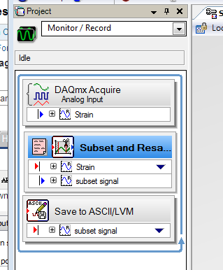
I have a cDAQ-9174 with modules OR 9237 with SignalExpress 2011 for strain gage measurement. After a few problems and doing some research on this forum, I discovered that the minimum sampling frequency for the NI 9237 is 1613 samples/second. However, I need a sample of about 1-5 samples/second rate as my tests will be the order of 4 to 5 hours and record 1613 samples every second will make my too big data file. On the forum, I found these workaround solutions:
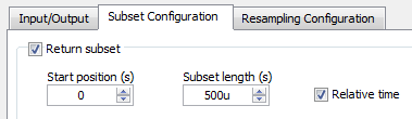
Subset and resampling (http://zone.ni.com/reference/en-XX/help/371268M-01/expresswb/subset_and_resample/) seems to be the most recommended, however I have a few questions about this. I selected a range of subset of 0s to 1s and then choose a resampling of 200 Ms. that seems to be the more manageable sampling frequency, but then I have a problem with the export of the data collected. I get a message that says I can't export to Excel, as the data are 'not continuous' and can only convert to text. However, the text file is not really useful as it breaks down the data in individual games and puts the time in terms of dt. For small sets of data, it seems that it would be possible to manually determine every moment given by point, but I will receive a large number of data sets. I have tried uncheck the "optimize to run once" but still not the same type of data file. What makes a kind of aggrivating, it's in SignalExpress data view tab can display a graph of deformation over time, that I need in Excel.
Another recommendation is to use the 'Statistics' using the collected samples, then changing the number of samples to change the rate. However, I prefer not to use this method because it seems to imply "at x time, average of the latter strain is y" rather than 'x time, strain is there' and I want just the value of the strain at every 0.5 s, 1 s, 1.5 s and so on (although I guess that how that differ from the subset and resample method?).
The last recommendation I found suggested to use an N-sample acquisition, set to read two samples and then set a delay of acquisition of post about 1000 m that would have been a nice solution, but it seems that SignalExpress impossible to compile all the samples to read a log file, that I have seen only two data points when I opened it in Excel.
I'd appreciate any help, thank you.
Hello MAF101,.
I ran your own project and it worked for me. I just used the following values:
It worked very well, I managed to turn on logging. Then, I tried logging information in a txt file using the instructions below:
I got the attached file below using a relative timestamp. It connected two samples per second.
Concerning
Frank R.
-
Wavy jagged singal of 9237 at no load condition
Dear forum users and employees of OR,.
I would be grateful to you if you can solve my problem. My specimen is a simple piece of plastic 1 0.25 inch rectangular cross section with a length of 8 inches. I'm trying to measure the deformation (with the help of use general TML, Japan 1 mm gage length extensometer) in the sample by hanging dead in the sample weights. I am able to strain using the cDAQ 9178 chassis, NI 9237 module with accessory NI 9944 quarter bridge. For a given weight (so the applied load becomes a static), signal (output voltage) must remain constant independent of time. In addition, I also expect that when no load is present on the sample, the acquisition system data above should show constant, but the deformation of almost zero output over time. What is my problem only after offset removal and shunt calibrated correctly with the help of the wizard of LABView DAQ, the above data acquisition system shows a strain of output wavy stair of significant variation between maximum and minimum, even when the sample is at no load condition (the sample is simply placed on the table). In addition, even after loading the sample with a certain amount of dead weight, rather than get a constant signal, I always get a strain of output wavy stair (with more scale position zero load) over time. Please help me get a constant output signal for the data acquisition system above with and without load on the sample.
Thanking you
KSRKM
-
I have a new USB-9237 with 9162 carrier, when I plugged the device was not recognized. NEITHER DAQmx 9.2.1 worm was installed before I plugged it, all I get is green light only flashes on the 9162. I went the 9237 with a 9239 and this device is recognized.
Measurement and automation explore worm 4.7.1
any thoughts or suggestions would be appreciated
Jesse
Hello, JENO,.
The version of the NI 9237 with d - SUB connector is not supported in the chassis USB-9162. It is because the device uses a different product ID and would need a different firmware, which is not currently supported. In order to use a NI 9237 module into a USB-9162, you need to use version RJ50, not d - SUB version.
Kind regards
-
NEITHER 9237 quarter bridge absolute accuracy
Given a NI 9237 bridge completion Module with NI 9944 accessory Terminal strain gauges and 120 ohms with GF = 2.11, how calculate we precision of strain?
I was told that the absolute accuracy for bridges of quarter is given by
Absolute accuracy = (Gain error * reading) + (error offset * range) + noise + half bridge watchkeeping tolerance tolerance.
Since I'm on the NI 9944, watchkeeping tolerance would be 500 uV/V (given by OR R & D). The tolerance of half bridge is given in the manual OR 9237 being 1.2 mV/V.
(1) it has no value of 'Noise' of entry for bridges on watch in the NI 9237 manual; We use only the sound of half-bridge?
(2) if I use a sample rate of 1,613 kech. / s (the rate guaranteed valid sampling for the NI 9237 module) and my system is always in his 1st year of use, always is my gain error 0.05%? It is worth noting that 0.05% applies to the 50 kech. / s ; If the gain error does not apply to my low sampling frequency, how can I find the error of gain?
(3) if my maximum/minimum deformation measures around 600 EU (microstrains), how can I change my values "Reading" and "Range" in the equation for absolute accuracy above, if they need to be adjusted?
(4) why the absolute accuracy for a quarter-bridge set up does not include the half bridge tolerance?
(5) is the equation for the conversion of precision of voltage precision for quarter of a bridge, of the strain
 , where U is the precision of the voltage given by the equation of absolute accuracy above.
Example of calculation using the values assumed for quarter-bridge:
Error error/gain Offset = 0.05%
Reading distance / = 25 mV/V
Half bridge noise = 1.6 mV/V * 3
Half bridge tolerance = 1.2 mV/V
Tolerance of watchkeeping = 500 uV/V
Absolute accuracy = (V/V 0.0005*.025) + (0.0005*.025 V/V) + ((1.6e-6) * 3 V/V) + (1.2e - 3 V/V) + (500-6 V/V) = 25 mV/V +/-1.73 mV/V
Accuracy of the strain =-4(V/Vex) / GF (1 + 4 (V/Vex)) = - 4 * (25 mV/V +/-1.73 mV/V) / (2.11) * (1 + 4 * (25 mV/V +/-1.73 mV/V))
How to simplify this precision of strain to get a reading + / range of precision?
Thanks for any help.
(2) if I use a sample rate of 1,613 kech. / s (the rate guaranteed valid sampling for the NI 9237 module) and my system is always in his 1st year of use, always is my gain error 0.05%? It is worth noting that 0.05% applies to the 50 kech. / s ; If the gain error does not apply to my low sampling frequency, how can I find the error of gain?
This applies at a rate of 50 kech. / s. lower data rate can have up to 0.20% gain additional error reading. This can be found on page 24 the unit operating instructions and specifications document
You get to know how to calculate what percentage of Reading (Gain error) I'd get according to what sampling frequency use? Otherwise, I guess I could use the error of gain of 0.20% in the worst case scenario.
Yes, I so calculate the error of Gain for the worst case scenario (0.2%)
(5) is the equation for the conversion of precision of voltage precision for quarter of a bridge, of the strain
, where U is the precision of the voltage given by the equation of absolute accuracy above.Yes, I think it's the correct equation.
It is more a matter of math - since you will be in the form of a reading + / a range (for example 25 mV/V +/-1.73 mV/V), do you know how I simplify or interpret the accuracy of strain after its replacement by the U-value?
Accuracy of the strain =-4(V/Vex) / GF (1 + 4 (V/Vex)) = - 4 * (25 mV/V +/-1.73 mV/V) / (2.11) * (1 + 4 * (25 mV/V +/-1.73 mV/V))
Just reuse the worst cases to calculate positive and negative values on 1.73mV.
-
9237 with deck full load cell: support cell_null_off_shuntcal.vi survey error 200077
Normal
0fake
fake
fakeEN-US
X NONE
X NONE/ * Style definitions * /.
table. MsoNormalTable
{mso-style-name: "Table Normal";}
MSO-knew-rowband-size: 0;
MSO-knew-colband-size: 0;
MSO-style - noshow:yes;
MSO-style-priority: 99;
MSO-style - qformat:yes;
"mso-style-parent:" ";" "
MSO-padding-alt: 0 cm 0 cm 5.4pt 5.4pt;
MSO-para-margin-top: 0 cm;
MSO-para-margin-right: 0 cm;
MSO-para-margin-bottom: 10.0pt;
MSO-para-margin-left: 0 cm;
line-height: 115%;
MSO-pagination: widow-orphan;
font-size: 11.0pt;
font family: 'Calibri', 'sans-serif ';
MSO-ascii-font-family: Calibri;
MSO-ascii-theme-make: minor-latin;
MSO-hansi-font-family: Calibri;
MSO-hansi-theme-make: minor-latin ;}Hello
I'm trying to use the example
load_cell_null_off_shuntcal.VI with a scale of full-bridge (Honeywell
Model 31, not amplified). I'm using LabView 8.6, cDAQ-9172 and NI9237. The
load cell is connected to the pins 2,3,6 and 7.Entries for the front side of the VI
are: excitation10V internal; mV/V 2.1492 (calibration sheet); weight max 10
lbs; resistance bridge 350 ohms (Honeywell specifications); 9237 shunt internal
100 kohm resistance; map of shunt R4 (default setting). I chose
"Do not offset null" and "shunt cal.This is the error I get:
Error-200077 occurred at DAQmx
Do a calibration Shunt (bridge) .vi:1 or the possible reasons:Measurements: Requested value is not
support for this property value.Property:
AI. Bridge.ShuntCal.GainAdjustYou asked:-61.980405e3
Valid values begin with: 500.0e - 3
Valid values ending with: 1.500000
If the "shunt cal.
green button is not selected, there is no error. I understand that the Gain
Change value should be approximately 1, whereas I get is much larger. The Subvi DAQmx PerformShuntCalibration
.VI (bridge) contains a "Call library function node" which I did not
find out how interrogate.Someone else has experience
with this error? Do you have any advice on:1)
How to 'see' the calculations being
carried out inside the "call library function node"?2)
What the correct shunt element
a full-bridge load cell location is? (although changing this location only)
does not eliminate the error, I can't find this info).3)
What can I do wrong with
my entries to cause this error?Thank you
Claire.
Hi Claire,
You must physically connect the SC of arm of the bridge terminals (normally R3). The terminal is not provided for the connection of external resistors.
See the example
C:\Program NIUninstaller Instruments\LabVIEW 8.6\examples\DAQmx\Analog In\Measure Strain.llb\Cont Acq strain samples (with calibration) - OR 9237.vi
-
Wiring of a NI 9237 and a torque transducer
Dear all
Newbie to these forums and equipment OR in general
I have a module OR 9237 and Labview using 2014. Recently, I managed to connect a couple of load cells to the NI 9237 and VI I built so that it works very well!
Now, I use a torque sensor and I was wondering if the NI 9237 is suitable for my piece of equipment?
I enclose the reference data sheet and the transducer that I have is the RT2A 5NM. There are a few areas that interest me on the datasheet are: (and please be gentl if these are simple assumptions or biases, I do).
(1) the rated power is of +/-10V
(2) the suggested nominal power is 15 - 24V (the NI9237 can provide this voltage?)
(3) the connection of the power cables seems to depend on the power supply voltage to the output voltage? (is it safe for the NI9237)
For point 1 in particular I can't seem to find any calibration for scaling? or are the transducers of torque generally considered a linear relationship between the highest voltage and the highest measure of possible couple?
Sorry if this all sounds pretty basic questions, the 9237 was module quite expensive so don't want to really rely on trial and error to build my next code?
Thanks for reading this post!
Hello world
Just to let you know.
Spoke the manufacturer. It is fairly standard if a transducer unit is already amplified and producing a voltage reasonable result such as + or - 10V. Then, the requirements are that you will ony need a data acquisition scalable to change the voltage in torque values.
In my case the torque-meter has been calibrated at the factory to read up to 5 nm and therefore the maximum 10V output voltage will be the equivalent of 5 nm. The torque/tension relationship is generally linear. So, for every volt should be the equivalent of 0.5Nm. The calbration manufacturer shows that standardized resting voltage is approximately 0.001V.
The voltage is relevant as an integrated amplifier in the sensor so the provider is a little higher than 15 - 24V rather than normal 2.5 - 10V requiring no amplified transducers. The NI9237 can provide a voltage higher than so a separate voltage must be applied. The voltage range is relevant only when certain factors such as the length of the cable and the amount of interference become apparent. As a general rule, use voltage as little as possible is the best that the actual voltage used by the transducer is normally regulated internally so if providing 15 or 24V won't have much impact (except if you have the above conditions).
Hope that helps
-
cRIO witch ankles are used by NI 9944 9237
Hello
I use a cRIO with NI 9237 module for the measurement of the strain with strain gauges. Here, I use the adapter NI 9944 to connect to strain gauges. I have a lot of SG and dissemination over a large area, so I thought about to build small boxes in which four cards are installed. Now I've not will always use 4 RJ-50 cables to connect the areas, only one. This cable be limited to 40 carrots (1 x RJ50 = 10 carrots), but use only the cables are also needed.
Now my question is what pins on the NI 9944 serve even one to connect a quarter deck?I hope someone can help me
Matthias
Hi Matthias,
Here, I have a document that should help you:
http://digital.NI.com/public.nsf/allkb/F47EFDB8B1992282862572AD007CE9C3
 ,
,RMathews
-
need to know if the NI 9237 - no compenstation such temperature on bridges and shunt calibration
need to know if the NI 9237 - no compenstation such temperature on bridges, also, I need to know if she calibration shunt.
Hey invzbl_rkl,
The NI 9237 - can do both remote sensing and Shunt calibration. You can see the details on how to connect the bridge in the USB-9237 user guide and more details about compensation in the article attached Developer Zone on measurement of strain.
Specifications and NI USB-9237 User Guide
http://digital.NI.com/manuals.nsf/WebSearch/B218E7E6DDB1D4518625738600784930Strain with gauges
http://zone.NI.com/DevZone/CDA/tut/p/ID/3642 -
Gap between the screws with the NI 9237 & Assistants DAQ
I have a set of scales attached to a NI 9237 module in a cDAQ 9174. I have two separate screws following the gross load cell output (mV/V). The two screws acquire through a DAQ Assistant. Two Assistants DAQ are configured in the same way, and yet they have different output values. Reads around 0.003 mV/V being not charged while the other reads 0.03 mV/V - an order of magnitude difference. Any thoughts on why this is? Thank you!
Thanks David,.
Finally, I followed him there down to a calibration offset null being applied to a DAQ Assistant and not the other. Is there a way to remove this discrepancy in the DAQ Assistant? It is not evident. I only noticed after DAQmx code conversion and managed to remove it it.
-
cRIO thanks the Module NI 9237 bridge in the Interface of scanning and Anti-Aliasing
Hello
I have questions about the use of a Module NI 9237 bridge with CRIO and its use in Scan Interface mode. The manual speaks the data rate of the module, and a (n) parameter that can be set to adjust (to a minimum of 1613 Hz) which in turn puts across the module built in anti-aliasing filters. It seems (but not explicitly stated) that this data rate setting is available FPGA programming mode.
Our application is currently running in mode Scan Interface, so my question is what is 'throughput' module (and therefore anti-aliasing filters) mode Scan Interface? And, if we have the analysis period the value 10msec (100 Hz), y at - it no filtering of the anti-aliasiing of software provided automatically by scanning interface itself related to the period of scanning? Or all the anti-aliasing extra something that we must build within ourselves? I looked at the example provided with Scan Interface and there is nothing more.
I don't understand about anti-aliasing, just need to clarify what is happening for this specific module mode Scan Interface.
Thank you
Andy
Hi Andy,.
I had to have a quick sleep on this night to get my facts right, hope that the delay was too long!
The minimum data listed in the 1613 samples/s are due to a forumla that uses the internal time base that is fairly well explained on page 20 of the Manual. The sweep period did not affect the rate of data, or to activate the anti-aliasing filter. My previous post was wrong in that sense, apologies!
This page helps explain mode of scanning pretty well too, but the best way to explain it is that even if the frequency of the module can be attached to 1613 samples/s or higher, the compactRIO will collect only 1,000 of these samples a second, or in your case if you are using a rate of 10ms loop, 100 of these samples of 1613. The anti-aliasing cut will be based on 1613 x 0.45 as you said and so will be 725Hz (not based on the rate of loop as I mentioned incorrectly)
In this case with these modules it is probably a good idea not to use a period of scanning slower than 1 msec for the reason you said - if you're worried about oversampling you can always you decimate readings in the software afterwards to take each readings from 1 to 10 (this page explains how do with an eerily similar situation!)
-
Hello
I'm looking to make a cal with the 9237 derivation. I built a simple FPGA vi which seems to work - I can change the sampling rate and perform a cal lag. However, when I activate the shunt cal switch, the output doesn't does not change. I noticed in the stitching of the SC Schematic of wiring. I connect these somehow? (No explanation is given as to what they mean I see). My understanding is that the 100 k ohms resistor internal to the Board of Directors and I did not connect anything to the outside.
Any ideas?
Thank you!
Hello
Wayne.C is right about the SC to connect to your sensor. Below, I have provided a link to the specification document NI 9237, references, page 10 (figure 3).
http://www.NI.com/PDF/manuals/374186e.PDF
-Jake B.
Maybe you are looking for
-
Need some drivers XP for Equium A100-338
Hello After having torn out of vista and put xp I lack these drivers can anyone help. Controller Ethernet PCI VEN_8086 & DEV_1092 & SUBSYS_FF101179 & REV_02\4 & 6 b 1 6D5B & 0 & 40F0 the drivers for this device are not installed.PCI\VEN_104C & DEV_80
-
Installation Failed for HP Laserjet 1200 Series in the new computer laptop with Windows 8, 64-bit
Name of the product - HP Laserjet 1200 Series PCL 6 Driver Operating system: Windows 8 Home Edition, 64-bit Error message: cannot find the series 1200 on the network. To locate manually click ok... Changes Made - this is an installation on the new la
-
Hey there, I have a HP Pavilion dv6 - 3172ee Entertainment Notebook, I recently got vga chip proplem with a black screen and I have tried everything and does not light up, so it's time to change the motherboard, I want to know is. can I update my mot
-
Windows Explorer stops and starts every few minutes on XP
I have Windows 7 every few minutes a message: "Windows explore is close and restart". I took the following steps to resolve this problem, but not completely as in computer science, I'm afraid I am groping in the dark: 1 - tried to clean the computer
-
No sound when playing audio files
the sound does not when I try to play music, but when I go into the Panel and test it, the sound works what should I do