Addition of drift in frequency of trapezoids
I'm using Labview 8.0 and I want to add the derivative of a square wave to the instantaneous frequency of a sinusoid at the same point in time. I tried to use the VI point by point, but they do not seem to work.
Does anyone have any suggestions?
Tags: NI Software
Similar Questions
-
Hi, I want to export my movie on DVD clips, burning them like AVCHD, movies are made on the basis of an iphone 6 1080 p 60. I want to keep the best possible quality. Can someone tell me what that best project settings I should use? Thank you very much.
Johnny
Thanks for the reply to my comments to complete Responses to your subject.
Factors in your planning...
First elements 13/13.1 does not support Windows XP, Windows Vista or Mac OS 10.7.
First items 10, 11 or 12/12.1 on a Windows computer is 64-bit application when it is run on Windows 7, 8 or 8.1 64-bit computer. Otherwise, it's a 32-bit application. This has implications on important it resources, particularly for your biggest projects in Premiere Elements.
Video mobile phone registered with a variable rate is a consideration for any version of Premiere Elements. If your cell phone video shows with audio out of sync and you use the hand brake to correct this condition, you should get good quality of the handbrake H.264.mp4 (just make sure that the export rate is comparable to that of the original in addition to changing the frequency of images to a number (use same as source) and selecting constant for this frame rate).
If any clarification on the above, do not hesitate to ask.
Thank you.
RTA
-
How can I retrieve the voice of a track to use as an acapella?
Hi, just like the title says I would like to know how to extract voice from a song so I can then use it as an acapella with Audition CS5?
Also while I'm here, using audition CS5, how can I determine the tempo of any audio file, I opened, and also how can I so to match the bpm of another sound file to match the bpm of the track I'm trying?
Thanks for your time
Dan
Your success with the voice of a song of isolation depends almost entirely on how the song was mixed and will vary widely. There is no perfect solution, well repeatedly artifacts that remain can be reduced in a mixture. Generally, you'll have the best success with the music where the vocals is panned to a specific location in the mix - usually dead center, but the tool can be used to isolate any position in the stereo field - without too much instrumentation to expand in this area. Bass sounds are usually mixed Center as well, you may need some additional EQ or lower frequencies spectral removal after completing the stage of extraction.
The tool you'll use in Audition is the effect of Center Channel Extractor , located under the Effects > stereo imagery menu. Start with the preset Acapella , then change the setting from custom for additional control. Select the region you want to isolate (it is often preferable to isolate the parts separately as, for example, the verses can be mixed very differently from a choir) and start playback with the open effect. Use the power to temporarily circumvent the effect, so you can note the differences.
Adjust the settings of phase shift and Pan to maximize singing with minimal instrumentation. Use the bandwidth settings to help reduce some of the low-end and high-end mixture that is not associated with the voice. The two vertical controls on the right allow you to adjust the levels of what is being isolated from all the rest. (Toggle to make a Karaoke mix.) On the tab of the Discrimination , the most important parameters will be Crossover bleed and Discrimination of Phase controls. You can set the parameters of the FFT on the Advanced tab, although I wouldn't recommend it until you are comfortable with the tool. Must necessarily know exactly what that never parameter, but listen carefully while you make adjustments and you will begin to understand how each setting affects the result.

-
Hi, I want to use three USRP to communicate with each other. But I met the question of frequency offset. To eliminate the frequency, first of all, I want to use the external clock
to synchornize three USRP. I know I should use REF in the Port, but I want to use PPS to?. In addition, there good ideas to reduce the frequency shift? I'm a newbie to USRP, answer you will be highly appreciated.
Hi llg9012,
There are 2 ways to synchronize your USRP. If you have only 2 USRPs, you can use a cable MIMO to share the reference clock and clock PPS between the 2. Since you have more than 2 USRPs, you will need to provide a reference clock (10 MHz) and a PPS (pulse per second) clock all 3 units. After you have plugged them in this way, you will have to use a property node to set the reference clock source and the time base clock source (which is the clock PPS) external.
Sharing these clocks will keep the relative phase between all 3 constant signals. However, whenever you stop and start the device phase differences will not be the same. If you are only concerned that your frequency and phase without drifting through time, using external clock sources is the best solution. If you need your USRPs 3 to have the same phase, you can use a sequence of training to align the phases. There are posted examples here the community that can be useful for your work request:
https://decibel.NI.com/content/groups/NI-USRP-example-LabVIEW-vis?view=documents
Discover the angle of arrival detection and 6 x 6 examples MIMO to see some examples of how others are synchronize their USRPs.
-
cRIO CPU % Total load drift up to...
My project has a cRIO 9074 in hybrid mode (an analog card is under the FPGA target, all others are the analytical engine).
The cRIO is a central control to 3 modbus slaves (palette function ModbusTCP block [i.e. not the server of e/s]). And is a 1 system SCADA via Ethernet/IP slave.
One of the slaves is a HMI XP (not the product NOR) which is the DB SQL base data record. How to get the plot shown. Weather I have deploy dynamically or "run as a startup" in the space of 4 hours, rails and the CPU % total load creeps upward. Finally, the HMI loses comms with the cRIO and stops the recording of data.
I have a feeling that the culprit is the component call loops of the total cpu load - but to confirm, I'll need to add it to the Modbus data to be connected.
The application has many parallel loops timed and non-timed, some for the comms ModbusTCP, others for any other logical - including a state machine in line waiting. For four hours, the state machine is static - i.e. no transition and the size of the data, as well as the frequency polled ModbusTCP and Ethernet/IP data is also static. I do it without programmatic changes to data between the cRIO and the outside world.
In addition, no recording on the disc of cRIO. On an error, I can post a message on the console. (I'll check on that).
If this was your problem, how would you debug?
by EITHER:
I used the System Profiler tool snapshot schedule about every hour. Smoking gun pointing to 2 live. They took more in addition to performing, means that only he excecuton totalled 6.5ms (immediately after deployment) and 24.4 ms after about 4 hours - and it drifted upward as the "worst offender" according to capture instant profler. In this vi I was using the function "get the queue" - without a queue of output associated.
I wired the reference of the queue for these screws. And up to 3 hours and my load CPU % is now in place.
-
Sync to external trigger in conjunction with a nearest pulse frequency device fixed...
I am writing an application running a scan frame. One axis of the scanner runs at a fixed frequency. I use a scanner high speed 5105 to get the data. The slow axis of the scanner is controlled by a servo with an analog input. I have will probably use an M-series card for analog control, but can also go with a 6713 (output only) or another Board. Fixed frequency Analyzer provides a clock line, I want to use to drive the 5105. In addition, the analog card must be synchronized in this. The entire system should be able to accept a trigger external devices, as it starts scanning at the edge of clock on next line.
I'm not quite sure about what would be the best way to do it. External triggering from other devices will be an indeterminate pulse width, so I can not just use it as a portal for the line clock. I am reluctant to do it in software (IE via the detection of changes on a digital line) because I want to be reliable started the next clock pulse. I have taken into account things like a counter/timer with a relaxing break, but which could lead to drift between the narcotics control and frequency scanner fixed. It seems just more complex that I think it should be, and it feels like I'm missing a simple way to do it.
Any suggestions?
Hi cshl,.
Good to know - the 5105 has a duty cycle of tolerance of 45-55% (mentioned on the page of the form), so that is why you cannot change clock speed from 3 to 12 MHz on-the-fly (though if you make small incremental updates over time, it would be theoretically possible).
With the additional information in mind, you might want to try the following on the 5105:
Use the external trigger as a trigger of departure (arm of acquisition).
Use the line as a signal reference clock (with a position of 0 samples for reference ~ 7500 are after initiation).
The problem with this is that you will have to re - trigger on each line - 5105 has a 2.4 rearm us time (also mentioned in the page on record). If this is unacceptable, another way that I can think of is to use a clock to external reference in PLL internal clocks of the bezel to. If you can provide a stable, a clock accuracy 50 ppm which is synchronized with your scanner within reach, would solve the problem of drift over time without having to re - trigger on each line (only acquire data continuously). This clock frequency must be between 1 MHz and 20 MHz in steps of 1 MHz.
We have no Council can take in an external variable clock up to 12 MHz (on-the-fly), but if you wanted to compromise a little bit the 6115 can enjoy up to 10 MHz, and has no obligation to cycle to 45-55% so it's maybe interesting look in.
As far as AO goes, I assumed that the clock line is declared after the quick scanner has completed his turnaround (ideally you do not update the zone of OCCUPATION during the lead time). If you have a signal Analyzer that you can use instead probably easier. If not, our peripheral series M and X series (but not the series AO 67xx) offer reference clock feature so if you go with the idea of reference mentioned above clock it may be easier to simply PLL the clocks together. These cards in a PXI chassis or are they PCI form factor?
I don't know what you mean by the sticking point about the need for two triggers. I think the idea is that we use the external trigger to arm the 5105 and clock line to trigger each record. However, if you do not need to generate a pulse double based on the clock of your line then you can use counters to do (our counters are redeclenchables with time to rearm in the ns range).
Best regards
John
-
I have a master HDCAM with stereo mix 29.97i & I try to scan the band to 7 FCP 23.98 p, but have audio drift on the capture.
The system that I use has a Kona card & I can choose the conversion cross without any problem.
The image looks fine in a number of tests, but the problem is that the audio that is captured with the image is out of sync.
Have been doing some research for a similar problem and have not found anything.
Anyone know what could be the problem?
Thank you.
Conversion of output with Kona... good. Conversion at the entrance with Kona... not very good. In fact, with a capture card, you can output and convert the frequency of images very well, but the capture and change, it does not work. Audio drift. Had this 2 Kona, Kona 3 and Decklink cards... and Matrox box. They simply cannot do it.
Therefore, enter it as 1080i29.97 and then convert to 23.98 after the fact, with compressor.
-
Question of timebase NI PCI-5154 digitizer drift
Hello NOR all awaits them:
We have a NO-PCI5154, used for several years now. We use it to capture waveforms of impulse which we care about timing relationships.
We operate the digitizer to sampling of 1 GHz and up to today, we assume the sampling rate is precise and constant. Today, a member of group doubt that since the digitizer specfication said, what the time base drift on "±7 ppm / ° C". So if this is true, suppose we have a Temperation of exploitation that is 20 degrees higher than the temperature at which the scanner has been calibrated, then the derivative can reach up to 140 ppm time 1 GHz which is 140 KHz? It would be a killer of our measures.
Please help clarify this question, then we can estimate errors in our measures.
Unfortunately, we have no data on the repeatability of the time base drift.
To calculate the frequency of real-time database, simply reverse the calculations that we've discussed so far. Measure a source very precise on the digitizer, and any change in frequency of the signal would be caused by the non-ideal time base period.
For example, you measure a signal from 10 MHz to 1 GHz, and its frequency is reported as 10,001 MHz. So, we're out of 1 kHz. 1 kHz = 10 MHz * Xppm, solve for x: X = 100 ppm. Thus, our sample clock runs at 100 ppm. 1 GHz * 100 ppm gives us a period of 0.9999 ns or ns 1,0001. As our frequency has increased to 1 kHz, the signal was compressed when being interpreted to 1ns dt. Thus, the real clock period was 1.0001ns.
Because it sounds like you can't control the temperature of your work environment, to the more specific measures that you can measure the time base clock drift immediately before and after taking your measurements. If you have run your tests in a controlled temperature environment, you might be able to get away with a measure not time base clock drift as often, but you should always run regularly. The reason for this is also due to the effects of aging of the time base oscillator (affects all oscillators). The accuracy of all the oscillators gradually drift or increase over time. Our specifications, take account of this drift in the external calibration interval, but if you're going to measure the actual accuracy, the time is another factor that will affect the accuracy of the time base.
For completeness, I also need to say, that when you measure your test signals ppm accuracy, this shows absolute precision, not only the accuracy of the time base, but also the accuracy of the source of the signal. So it is very important to have a precise source for the test signals.
I hope this helps.
Nathan
-
Calibration frequency Offset transmitter and receiver with USRP® material
Hello everyone, I read the scripts provided by The Mathworks on the frequency of calibration offset transmitter and receiver with USRP.
The USRP® transmitter sends a sinusoidal signal at 100 Hz with the MATLAB, sdruFrequencyCalibrationTransmitter.mscript, the USRP® receiver. The USRP® receiver monitors the signals, calculates the transceiver frequency shift and displays in the command window MATLAB for calibration with the MATLAB script, sdruFrequencyCalibrationReceiver.m. At the level of the receiver, frequency offset will be calculated and displayed in the command window. The program uses a Spectrum Analyzer to show the spectrum of the received signal. In the program, the corresponding sentense is '% display frequency spectrum. step (hSpectrumAnalyzer, rxSig); "Based on that, I thought that the spectrum analyzer would show the spectrum of the received signal. However, the Web site corresponding site shows "to compensate for a shift in frequency of transmitter/receiver, add frequency offset on the Central frequency of the receiver object SDRu system. Be sure to use the sign of the offset of your addition. Once you have done this, the spectrum displayed by the Analyzer of spectrum of the receiver system object must have its maximum amplitude at about 0 Hz." What I'm confused is, why the Spectrum Analyzer should have its maximum amplitude at about 0 Hz, not other values? Is it because of the characteristics of the USRP itself or the Analyzer of spectrum shows is the value of the difference between the Tx and the Rx after calibration? I use neither-USRP 2920. Your response will be much appreciated! Thank you!
The matlab mfile is found in the following links:
Yes if two devices are not locked to a reference clock, 10 MHz for the USRPs you will see a shift in frequency.
Specifications in ppm, ppb can give you how it can be:
http://digital.NI.com/public.nsf/allkb/2A0B9D3F365DEDEF86256BDB007354EDBye!
-
How to lock the frequency of sampling for 5673 and 5663
Hello
In general I try set the transmitter and the receiver. It seems easy to lock the carrier frequency, but no matter what I do, I seem to have a drift in my sampling frequency (order of 1 ppm).
Is the sampling clock in the digitizer 5663 linked to the same reference like OL clock? ... I didn't know that I needed the mechanism TClk here since I don't care for delay...
Any thoughts are greatly appreciated. Here are some details.
I use the 5673 as transitter and 5663 as receiver. I noticed as follows:
1. when each use a "reference clock Source' = OnboardClock I have a carrier notable offset to the receiver (for example carrier 5.8 GHz has ~ 7 KHz offset) and that's fine.
2. when each use a "clock reference Source" = clock, with the physically attached chassis PXI, I see no delay perceptible carrier to the receiver.
3. what 5673 uses 'Reference clock Source' = OnboardClock, using 'Reference clock Source' 5663 = ClkIn (ClkIn/Out physically attached), I see no delay perceptible carrier to the receiver.
-
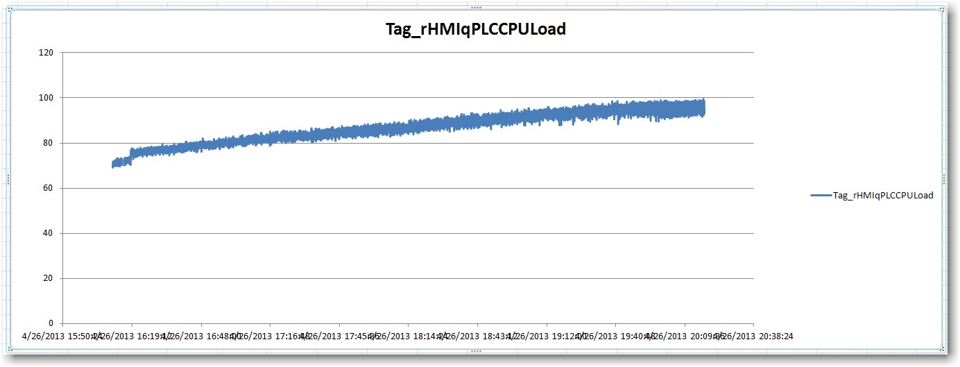
Generation of data and acquisition of high frequency problem
The fitting requires a fishing signal (32,764 KHz) saw tooth (0.3 Hz) signal output to drive the laser and acquires the signal from the output of the detector. I use the NI USB-6356 data acquisition with the speed limit of 1.25 MECH. / s.
I put the generation mode like "Samples continues", samples of writing/reading of 1.2 M and 500K (Hz) frequency in the DAQ Assistant. I also tried 500K and 500K.
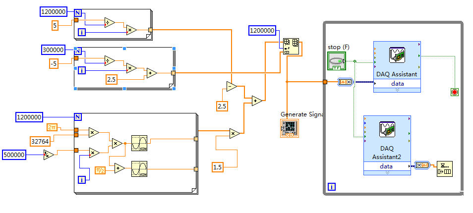
The scheme of vi is illustrated in the following figure.
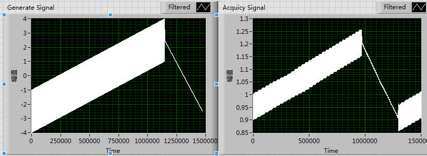
Of the front plate, the generation of signal is normal, which may be seen in the left side of the following figure. But signals a lot of periodic fluctuations that will appear if the right side of the figure. In addition, the siganl acquist go all the time.
I think it's maybe a few errors with my setting of the sampling frequency, I tried a lot of time for a change of pace, but it seems unnecessary.
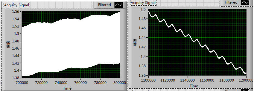
These fluctuations exist not only in the growing period but alos can be seen in the declining period, which is shown in the following figure:
I tried to solve this problem for almost a week and try a lot of different rate, but all fail.

Could someone give me any suggestions please? Thank you very much!!
Thanks SOSOSO much for your reply immediately every time!
This is my first time to write the Labview program with data acquisition
The attachment is the field of Vi.
I'll read the Web page that you offer, thank you very much once again!
-
We have equipment OR measurements of charge 3 cell, it consists of a NOR-6220, SC-2345, SCC-SG24 (2) and (2) SCC-LP02. During a recent calibration system, I noticed that all channels showed considerable drift when the load cells were out load condition (and probably under load as well but I didn't not test to check). For example, a cell of weighing capacity of 25,000 pounds was a no load measure 142 pounds and an hour and forty minutes later, it measures 56 pounds. The degree of drift seems to be linked to the section how long the computer containing the material was turned on, but continues well beyond the long warm-up period specified in the material master records. in the previous example, the load cell was measured after an hour and a half additional 25 pounds. I ran a test using a simulator and has seen the same drift, it must ensure the material and not the load cells causing the drift. I also have one of the load cells connected to different materials (cDAQ-9178 and NOR-9237) and have not seen the same degree of drift.
Basically, after warming of the system for 4 hours stabilized enough steps to make all without consequence drift continues for the duration of the test. This amount of warming seems excessive in relation to the other material OR that we have. Should I be worried? Others know about this?
Thank you for contributing to knowledge or information on the question, as I am experiencing.
TessaI was finally able to remove the drift by removing the low pass filter of the installation. Appearently the SG24 and LP02 don't play well together.
-
Change the frequency AO AO DC voltage scanning scan?
Hi all
I am very new to labview, but find the forums and examples extremely helpful. I probably spend 50 + hours to familiarize myself with tutorials and general information, but I am at a point where I need your help.
I'm unable to change the example "AO frequency sweep" found here (see custom_sweep_1.VI) to allow me to sweep the voltage. My instinct is that I don't need of the ' waveform buffer generation VI ' and that I should be able to remove the associated entries since I'm only interested in a sweep of DC voltage. It is also called create_log_frequencies.VI, and I'm fairly certain that I can use it as written and simply change "frequency", "tension". My work of the custom_sweep_1 changes are attached as custom_sweep_Voltage.
The problems I am having with the edition of custom_sweep_1 are:
(1) I don't think I understand very well how or if the parameters associated with waveform buffer generation VI relate to a sweep of DC voltage.
(2) an extension of 1): the loop depends on the samples and Cycles by buffer and I don't know how / whether to replace these values
(3) the .VI DAQmx Timing (sample clock) receives its sampling frequency of output waveform buffer generation VI, but I think I can use 1/scan time to replace this (?)
(4) the DAQmx Write.VI gets waveform buffer generation data, but if I can get around this VI and AO tension of wire directly to write DAQmx then I think I can use minimum voltage as my entry of data (?)
(5) after the implementation of these changes, the custom_sweep_Voltage runs, but I get error 200609:
"The possible reasons:
Generation cannot be started because the size of the selected buffer is too small.
Increase the size of the buffer.
Choose the size of the buffer: 1
Minimum required buffer size: 2"Task name: _unnamedTask<3A>"
I also note that I tried other ways to create the sweep of voltage DC VI:
(1) I have tried change the tracer IV example (found here), but it's much more confused than change the frequency sweep.
( This tutorial and sample 2) block diagram looks like straighforward, and I also work on understanding what Assistants DAQ 1,2, 3.
Any return would be great. I think it is clear that at the very least, my poor understanding of 'buffer' is if the cause of my confusion about the change of frequency scan, please do not hesitate to share any information you have.
Thank you very much for the help,
-Esperanza
Additional information on my project/progress using labview follows below:
My final goal is to determine whether or not the resistivity of a sample of organic driver changes over time. For this I want to compose a VI simultaneously sweeping the output voltage DC-5 to 5V periodically during 24 hours and measure the voltage drops to my load resistance (to determine the current in the circuit) and the sample. I use a USB 6259 DAQmx and that you have correctly configured my circuit. I work two screws that I created with the DAQ assistant and by changing some of the examples, I found online. Output voltage (of an AO) but I have to manually select the voltage value. The second reads voltages in three samples of interest and writes the data to a PDM file. If you've read this extreme sensation and still make a contribution, my next goal after finding how to sweep the voltage is to combine this with my VI measure VI. I think it will be relatively simple, but still, I rejoice in all your comments!
I solved this problem. I have changed my approach to be similar to the last link in my post. AO frequency scan approach is much more complicated that I need. Thanks for the help.
-Esperanza
-
Get the value of the frequency of the power spectrum
I'm rather new to LabView and want to measure the frequency of the peak in a spectrum of power of a real signal. In addition, I want this value of frequency and amplitude to save to a file. Right now I am able to trace a spectrum of power using an express VI, which gives me the correct frequency value in the graph.
However, I'm not able to extract the value of the frequency with different screws, I found in LabView after browsing through the various discussions in this forum. Can someone tell me please in the right direction? I use a digitizer NI PXI-5124 to record the signal in a rack of NOR.
If it is the dominant frequency you are looking for you can use the vi extracted a single signal. You can also change this vi to include the details of the search if it isn't the dominant frequency, I have not included it in my example, but you can check it in the help file.
Ian
-
I have included my code as version 8.5 for those who have not yet upgraded to 8.6. I have also included some screenshots so that you can replicate the results I got. I hope that some signal processing guru can shed light on what I mention it further.
This VI convolves the signal of impulse response of a simulated servomotor which is essentially a damped sine the input pulse which is a step function. The signal resulting convolved should be IDENTICAL to that of the step response of the engine which is RED on the display 1. As you can see the convolution that results in table 2 shows the same structure of frequency, but its magnitude is INCORRECT. As you can see in the catches of 2 screen sizes differ by a factor of 2 & done the sampling frequency of the wave. Why the sampling frequency, impact on the scale is also very strange & disturbing.
Would appreciate any corrections & explanations so that I trust the convolution of the other wave forms of entry than just the step function.
OK, I think I have it working now. Your premise on the effect of sampling on the derivative is not the issue. Does it affect what the FREQ of levy is the basis of time of convolution. As the convolution product is not continuous but discrete the length of the array should be taken into account & the sampling frequency must be consistent with this length of array as well as 1 second corresponds to 1 second. If sampling freq is 2 kHz & the length of the array is 1000 then to get the correct time base by a factor of 2 must be taken into account. In addition, to take account of the DC, shift of the ZERO gain factor must be added to the convolved signal to get the correct size.
Thanks for making me think more deeply.

Maybe you are looking for
-
Help! Does this affect my Wi - Fi connection speed? Install a Virtual Machine.
I went recently through a malware attack on my PC of 10 windows trying to reset my Twitter, but there is no way in, unless I want to find my password, I went through an application and he broke my PC, it started failing and it is very slow. Then, I u
-
Cannot receive messages in Outlook Express
Recently (for the first time) I consulted my ISP mail service. Since then, I have been unable to receive messages in Outlook Express, even if I can send them. When I check new messages, I get a connection, but no new messages. Some of my messages are
-
Hi all Currently, I measured distance of a piston of my TEST machine running with out LVDT (analog voltage to a data acquisition card). How to measure speed, because I see no way to measure the piston travel time! I use LV 8.5. Thank you
-
I am download Kaspersky anti virus on my computer. It doesn't let me download it. The error message says something about the signing of data. I contacted Kaspersky and they tried everything and it doesn't work. They recommended that I contacted m
-
The power of the laptop failed during one of the many attempts to install the updates. Now I can not start due to error 0 x 80070050 and restore points do not work. Of course, I don't have a return to the top. Any Suggestions?Thank you