Branch voltage source currents abm
Hello
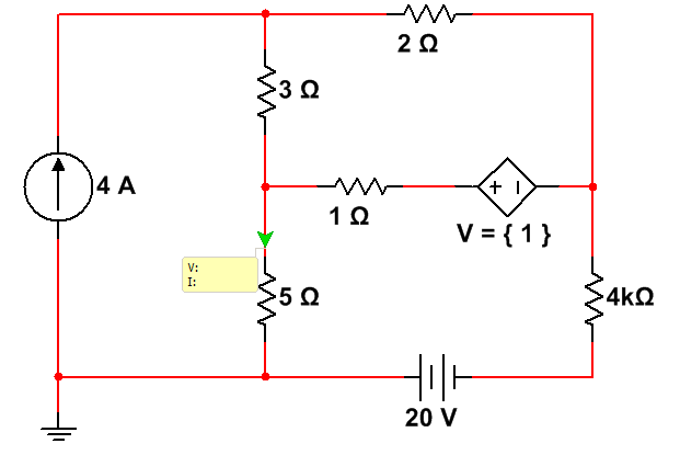
How to access the current through resistance in the voltage ABM source?
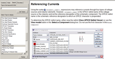
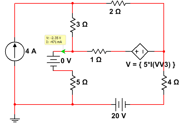
I finally managed to access the current through the resistance. Others may see "Common SEO" in the Multisim help.
Tags: NI Software
Similar Questions
-
trace voltage Vs current graph
I have ground voltage Vs current graph. In this chart if you want to see your old graph if you select the time and date, if u get the old value. Please tell me how can I connect this value if I get this value when I select the date or the time.
It would be much easier if you posted the missing VI so that we can see what it is you do.
-
How to display the voltage and current of synchronously
Recently, doing a project on the acquizeing voltage and current synchronouly, then display. the design is welding a resistor(1%) 0.5 ohm in NI 6251 entered analog of her HAVE differential, then acquired the differential voltage at the input to convert current. At the same time, I hope to recover the path of analog input voltage. My problem is that the current profile data. Please help me .the program screenshot is show below. ---1. Perhaps you ask why not use no. - a way to get voltage at all port of AI, then in the use of the software less to get a voltage inputs HAVE. in this way, my problem is solved. I try, but the current accuracy is failure. because my current range expect is 1uA ~ 100mA. precision current samll won't be promised if you use simple ways for granted NOR 6251 voltage. NEITHER 6251 device spec (HAVE an absolute precision) (v) nominal range sensitivity absolute Accuracy (uV) 10 1920 112 5 1010 56 2 410 22.8 74 0.2 6.4 0.1 52 6.0 (I want to use this range to measure current samll) - cordially Shawnh.Chen
shawn1 wrote:
1. how show the waveform by accumulating 1 d data table, rather than showing all 100 acquisitionUse a waveform graph. Graphics keep history, you do not have to accumulate the data. He does it for you on the screen.
shawn1 wrote:
2. What is the minimum unit of identification of the TSC103IPT amplifier? I doubt that the 0.5uA can be identified? (0.5uV = 0.5 ohm * 1uA) Because I can't find anything on the auccary in TSC101IPT datasheet.The amplifier is analog. Thus, he can win anything. But you should really think about a higher resistance if you really want to measure this small of a current.
-
Calibration with the voltage source - float connections
Hello
I want to calibrate a PXI-6133 DAQ with a floating voltage source. It says in the manual of the calibration connect the positive output of the Stallion to the AI + pine. Since my source of tension is floating I connect the negative output to GND. HAVE I - HAVE GND short or leave - not connected?
Thank you
Jens
Sorry, I just answered this question for my part it is logical to short-circuit the entries HAVE - and GND.
-
calculate the symmetrical components of voltage and current
Hi all. I work on the calculation of symmetrical components of voltage and current in Labview. I have included the relationship between the symmetrical components and sequence as photo 1 voltage. I'm going to use this calculation for several times, so I wonder if anyone has some ideas far better bc I wired just so much together to realize the expression. It seems aweful. Any suggestion? as built-in function to achieve this function? Thank you
Let's take a look on your form (you don't say what is complex, etc, so modify as needed)

For example, here is how you create the matrix A to an alpha given.

Similarly, you can create A ^(-1) matrix (your definition of A and A ^(-1) seem incompatible, otherwise you could just pick matrix inverse of A). After that, you can multiply with you V123 vector using AxB.
-
Chroma DC power supply RS232 communication (read problem of over-voltage and current)
Dear all.
I chroma programmable DC power. Based on the programming of the Instrument manual I develop using RS232 communication. Based on the program I can set the voltage, current, over-current protection, protection against overvoltages and make IT / OFF out put supply perfectly.
But I have to read the measured values of the output power as current and voltage. Measured applications are the voltage and current of the output of the power supply. My problem is two of them read at the same time. Currently, the reading is only voaltge or current (if the first request is v? it is voltage read out but no reading for the current) and if the first request is CURR? the reading for the current, but not for VOLT? The status message is OK, even if it is to read values.
Thanks in advance
What I see in your program, it's that you do not use the stop for reading character. For your writing, you do the hard with all these concantanate string functions. You can set the stop character for all entries with a node unique propert - "ASRL end Out.
-
Multisim: Parameter Sweep of piecewise linear voltage source
Hello
I did a transient analysis of a 4-stage-amplifier with a certain input pulse generated with a piecewise linear voltage source (screenshot 1).
Now, I want to do a sweep of parameter analysis by varying the amplitude of my generated pulse.
What is the right for this parameter? (screenshot 2)
Thanks in advance,
Johannes
Hello
You will not be able to do sweeping device/model parameters because the Amplitude of a pulse source is not actually a device/model parameter.
For this, use the parameter of Circuit of Mutlisim feature. See the circuit attached for reference.
I defined a new Circuit parameter (view-> parameters of the Circuit) called "Level" with a default value of 1.
I assigned this setting to the "Pulsed value" parameter of the element of impulse voltage source.
In the dialog parameter Sweep, I chose the Circuit parameter as the type of the parameter I want to scan, and then I selected the parameter 'level '.
I would like to how it works for you.
-
6009OEM output voltage and current
Hi all
Just try to make sense:
http://www.NI.com/PDF/products/us/20043762301101dlr.PDF
Page 3 says: high output voltage (push - pull, I = - 8.5 my) = minimum voltage 2.0 v maximum voltage = 3.5V but where can I find out what current can it provide and continue to produce an output voltage more than 4.2V? (4, 2V is the worst case for the high threshold of logic of a chip, I want to control).
Thank you!
J
Hello J,
As you mentioned is the maximum voltage of 3.5V when you have a high output voltage (push - pull, I = - 8.5 my). If you need more than 3.5V then you might need to change to an open-drain output. As you can see from the link you provided that you would receive a maximum voltage of 5V.
If you do not use an open-drain output you have to combine with a pull up resistor.
I hope this helps.
-
my project is to measure the voltage and current by using the view of laboratory.
Dear Sirs,
I have a project to measure parameters electric ac current, voltage, power factor etc through aquisitioin of data with labview. Can I do this? If yes then kindly help me with some opinions and ideas. I'll be very grateful to you.
Muhammad Azam Hanan.
Student of the University of engineering and Technolgy, Lahore, Pakistan.
-
Non-linear voltage with current variance
[10/07/2014 edited by moderator as requested]
I'm trying to measure the design resistance of the voltage across my test using NI9205 sample. I have a power supply current constant and 30 cm of wire across copper as connectors to my example. I'm exploring various levels from 20 to 500 my.
However, the resistance or voltage/current ratio do not seem to be constant on current values. Current increase seem to increase the resistance of .01ohms.
I change the lines in my daq between 200-1-5 a 10 V.(+-) of heat due to the current, and changes in the sample of it are not a factor. Is that an offset voltage when changin ranges that affects it? I use the daq with no custom scale Wizard. I do, however, collect samples from 1000 to 1000 Hz and their average.
Tried to use 4 wire measures?
0.01 ohm in 30cm copper wire... seems reasonable...
so: two sons for the current and two sons for the measurement of voltage (differential). Guess the image below that is screwed is current and voltage

-
scanning voltage and current measurement for Keithley 2400
Dear all
Hello
can someone help me?
Despite days nearlly10 I am option to find any program LabVIEW 2010 for sweeping the voltage and measure current who works with RS-232, I have a end not have nothing exept examples read single and multiple data. I tried to SmartData labview and changed a few prorgram gpib to RS - 232, but I couldn't.
In another attempt to find a good VI "votltage scanning and current measurement" that work with RS-232 in labview 5.1.1. I have converted in 2008, but it takes old driver (ke24xx.dll) and do not work in my labview 2010 and I could ' t find older driver.
My thesis project was halted in those 10 days, and I couldn't do anything for our keithley.
Please helpe...
in the following, I have attached these files:
1.-first, what voltage scan that works with GPIB
2 - Vi that I change the gpib for visa (rs232) port that I don't know why it doesn't work.
3. it is Vi related to the "sweeping and current measurement votltage" that works with the RS-232, but it takes old dirver so I can't use it.
4-slot-VI necessary for the implementation of program 3 (but there is no driver for these subVIs) was attached to the reply message of this post
If any body has this program ("scan votltage and current measurement" running rs - 232) please send to me
Thanks in advance.
None of you attached the screws are the driver OR you spoke. There is no conversion required for this driver.
-
PIECEWISE LINEAR VOLTAGE Source BUG
I want to source PWL allows to analyze signals from my digital oscilloscope.
File MEANDR.txt contains 5000 points of voltage (mV) in the time domain.
(1) if I'm going to use this file with the option 'Use data directly from files' there will be no signals at the output of the source.
(2) if I go use the option "enter data points in the table---> Initialize the file" and press the button "Run the Simulation" Multisim breaks down... but it starts working properly if I'll burn the original file of 5000 points to 2000-300 points. (File MEANDR_MODIFIED.txt)
You can fix this bugs?
Thank you!
Hi, ZG,.
Your data will give Multisim a problem because of the format, Multisim expects the tension and the time of two columns. On the column of time data range from 1 to 5000 so Multisim will have to simulate for more than an hour and in the world of simulation that is an eternity. I changed the data so that Multisim simulates only up to 5 sec. Your column of tension is supposed to be in mV on each line, you will need to place a mili at the end otherwise Multisim going out KV. Using Word and Excel, I changed your data to something that Multisim may include and the file is associated.
-
Variables for voltage and current on each component (for use in graphically the diagram)
Hello
I have a very simple circuit containing only a source of AC voltage and resistance of two series.
I want to draw the voltage of the source and each resistance. I can't find any variable involves pre right now, I know I und came to the value of the resistance.
for example
UR1 = I * r1
USource = I *(r1+r2)
It's pretty boring... especially because that put in square brackets does not work.
probably the cause variables containing itselfes media.
hope you have an idea
THX
Hello
The way that you have set in place now of things is correct. Multisim, as well as most of other circuit simulators, monitors the node voltages, no voltage drops. When you draw your diagram, Multisim assigns numeric node names to each node. That's why you see v(1) and v(2) and not something like V (R2). To find the voltage drop in R2, you will need to calculate V (2) v (1). To know the name of each of your nodes (also called threads), simply do the following:
- Click Options > properties sheet
- For option Net names, select Show all
- Click OK
To make it easier for you, you can name a few nets to something that is easier to read. You can do this:
- Double-click on the net you want to rename (the net is the wire you drew connecting elements)
- Enter your name, preferred net in the space provided
- Click OK
Hope that answered some of your questions.
-
Venue Pro 8: use the charger with a little more voltage and current?
I just bought a Dell came Pro 8 tablet used running Windows 8.1. The seller didn't have the original charger, so he gave me a 12W of Apple loader that had taken out nominal 5.2V and 2. 4A
Is it okay to use this charger for my Tablet? Any potential problems in the long term?
Thank you!
I'm sure that the voltage is OK to 99.9%. The extent of the current note goes, which is often misunderstood. The rated current for a charger power or power is the maximum that the charger/power is able to provide. It could be evaluated to a zillion amps, but the equipment to which it will draw only what it requires.
-
Hello guys,.
My question is provided in the topic, you have an idea about that? your help is appreciated.
ELA
Hi Ela,
For almost all devices supported by DAQmx, you can't. When all AO channels have the same motive, connecting them in series would be short the output channel on the ground, which is bad.
However, there is one exception: the SCXI-1124 module has channel-to-channel isolation, which allows channels to be cascaded to output voltages: I can cascading the output voltage of an SCXI-1124 module?
With channel-to-Earth isolated peripheral (such as NI 926 x or NI 623 x), you can cascade multiple devices together, but not multiple channels on the same device.
Brad
Maybe you are looking for
-
You can still get an annual plan of storage icloud?
You can always buy an annual plan of storage icloud or is the only option to pay per month?
-
How can I get a continuous square wave to the duty cycle of 50% on one of the analog lines?
Hello, I had recently just buy an analog card to our system, and I'm still very new to labview. I have the PXI-6723, and I need to produce a wave square of 0 to 5 volts continuously. I used the square wave generator and used a writing funtion to on
-
'0x61011bad' in '6500 a' printer problem
HelloI have a printer all-in-One, model 6500 'has. " It shows a 'General error' message number "0x61011bad".I tried turning power on and off, but nothing helped. Windows xp users * Connected by USB. Thanks in advance, Eitan.
-
Ownership/permissions of issue of the use of files
So, my problem is this: I have a 2.5 gig folder full of music that I do not have access to. No matter what type of media player, I use, whether it's WMP or VLC or anything in-between, I get an error stating "You don't have permission to open this fil
-
Configure the link point to point switches VSS backup
I have two basic switches in each office linking the two by point to point one desktop. Now I have the second point to point which I wan to serve as a backup. See fix main diagram point to point is set up in Vlan not as routed port... What is the bes