Buffering 10 HAVE on sbRIO
Hello
I use the FPGA Wizard to 10 analog inputs for a single buffer RIO. I need the loop rate must be at least 15 kHz in order to identify an entry of 7 kHz square wave. I can usually get the signal buffer very well until I try to do any sort of manipulation of data, then I have overflow problems and increase the size of the sample (which is generally too slow to be as sensitive as I'd like). Is there a way around this problem? Aid only would be made variable help? Several VI?
Thank you!
-Eli
If you only measure the frequency of the signal using analog inputs, I would treat the data directly on the FPGA. the rates that you describe should not be a problem for FPGA. Look first at your algorithm.
Tags: NI Software
Similar Questions
-
Someone has a vi for LCD with port COM for SBRIO
Hi people,
I have a SBRio-Board and you want to drive a LCD on the COM-port.
Is this possible?
Someone has a vi to do this.
I know, it's possible with FPGA lines, but is not the normal/best way COM port?
Greetings, Ruedi
If you look on the LabVIEW tools network and search for LCD a few possibilities appear. http://www.ni.com/np/app/main/p/bot/no/ap/lvtn/lang/en/pg/1/sn/n25:software, n21:28/sb/default /? q = LCD
It is said expressly in the box to Reach tools that it is via RS - 232 interface. Although not your specific device would it be worth the trip.
Its interesting that I would have liked to have a few years on a project using a touch screen of Reach.
There is also an example here http://www.ni.com/example/31079/en/.
I hope that this will help.
Warrior of wire
-
Interfacing engine Lego NXT sbRIO-9636 Eval Board
Hello
As a newbie to sbRIO, I would build a simple Quadrature counter.
Recently, I attended the great build your own Embedded system workshop and have a sbRIO-9636 running a updated the Quadrature counter sample project AND originally designed for the sbRIO-9631. He works a lot using the digital encoder built into the daughter card.
Then, I want to use a Lego Mindstorms NXT motor (PN 9842) encoder. I will feed the outboard motor so for now I just up/down count the encoder. Here is the wiring that I intend to use on the map of my daughter:
Channel that has the encoder (yellow wire) will go to DI2
Channel B (blue wire) of the encoder will go to the DI3
Common 0V (red wire) goes to DGND
+ 5V (green wire) will go?So my question: is there a point on the map the sbRIO-9636 girl, I can securely connect to for + 5V power of encoder? Moreover, these colors of son are Lego Mindstorms extension cables when they are cut and stripped.
Any help would be appreciated!
jimmyservoAccording to the quick reference for the sbRIO 9636: http://www.ni.com/pdf/manuals/375933a.pdf
There seems to be + 5V on 49 and 50 of the J502 connector pins. This connector is available, or you use a daughter card?
Other options would be more hackers IMO, such as the drawing of the USB connector 5V.
-
Hello
So I have a sbRIO-9636 and I worked on it for a while. Have had no real problems with it, but the other day when I started it up it is just on the network. After checking the hardware (cables and switch), I noticed that the connector ethernet LED are lit (green) as soon as the sbRIO is turned on even if there is no ethernet cable connected. If I plug in an ethernet cable activity LED begins to blink continuously. There is no sign of her on the side of the switch. The port State LED is off and there is no trace of the sbRIO MAC address. I tried to put in safe mode, but the same behavior just keeps repeating itself.
Needless to say, it does not appear to the MAX and he cannot be crazy.
I'm about to get your hands on a cable to try to connect to the serial port and see if I can get some information about the function of the Console, but I thought I'd check if anyone here have seen this behavior a sbRIO and perhaps successful solve. It's sad to say, I did not have much hope for unity but maybe worth it.
Thank you
Nimgaard
Nimgaard,
There is nothing of National Instruments can recommend to repair this unit. I would recommend calling our support and explaining what happened. They will know if the unit is still under warranty and can you get in touch with one of our RMA coordinators who can help you deal with this. This option can be less expensive than buying a new unit.
-
SBRio has another Vesion real-time
Hello
I'm using Labview 2012 and must stay with this Version for a while.
So now my computer is it time Version 12.0.0 real.
Now I have a SBRio Council with the Version time real 13.0.0.
Is it possible to 'downgrade' the SBRio version 12.0.0.
Or what is the best way to get out of trouble?
Thanks, Ruedi
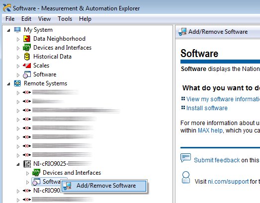
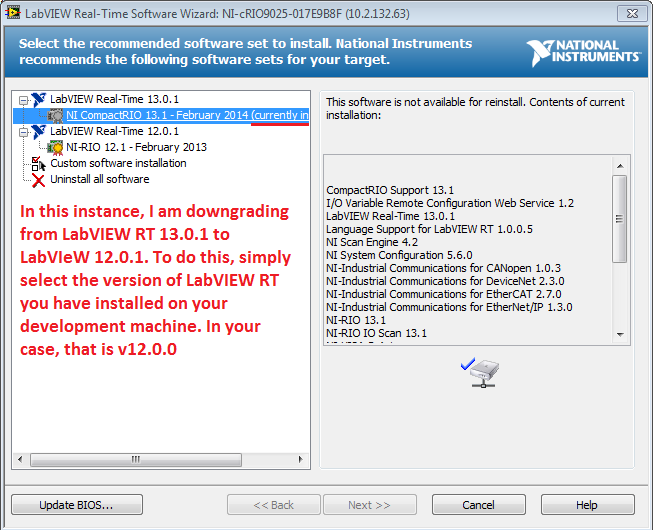
Hi Ruedi,
Yes, you can downgrade the software currently on your sbRIO. Since you have LabVIEW RT 12.0.0, you can open MAX and expand remote systems. Find your controller and which expand as well (see photo below). From there, you can right-click on the software and select Add/Remove programs. In the example below, I have LabVIEW RT 13.0.1 on my controller cRIO, but I have LabVIEW RT 12.0.1 on my development machine - it is a problem. To resolve this problem, I can simply choose the version of LabVIEW RT compatible with my development computer (that is automatically populated in the window). Once you have finished configuring your software, it will push the software to your sbRIO. I hope this helps!
-
I have a sbRIO 9602. He worked well with an executable running when it lights up. Now, the system is not responding. I can't reach it to the static IP address, that he had. The status light does not come on when it is running (no POST?). I tried to reset the IP address but MAX is not discovered it. The console out seems to be not working either. I can try, or should it be sent in for repair?
Hi Skryger,
If the Self Test (POST) does not occur, as evidenced by the lack of light when turned on the status light, then the jury you have is probably damaged and will need to be repaired.
If you want to troubleshoot more yourself, I would first check the supply voltage that you apply to the Single-Board RIO input terminals is not reversed and is between 19-30VDC with a multimeter. If you can check that you apply voltage to the input terminals but the Single-Board RIO still don't POST, while it is damaged.
If you want to dig a little deeper, you might probe both terminals of F2, the fuse input power (it's in the corner of the nearest the power connector card), with a measure of resistance or continuity AFTER you make sure that you unplug the Single-Board RIO of all power. If the fuse is high impedance or open, so very probably something accidentally shorted connections on the circuit board causing a surge of current, blowing the fuse (2Amps, not replaceable, the sbRIO-9602 User Guide).
Another possibility for the damage is documented in the User Guide on page 11. If Single - Board RIO is used as a constant in a system point and more of 3Amps of current through its plan to return to power, constituent of protection will be fuse opened. You need to check the external devices that share the power used for Single - Board RIO have their own lanes dedicated to the power supply ground.
You can contact OR for a return authorization of hardware (RMA) to www.ni.com/support (here is a step by step checklist for info to be ready when you call). After contacting the support, they can help you solve what may have spent in Single-Board RIO and determine if the Single-Board RIO is under warrantly also.
Kind regards
-
LabVIEW does not allow me to add SBRIO project, but SBRIO appears in MAX
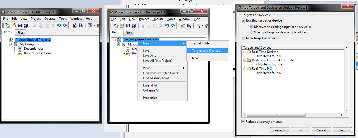
Hi, I have my SBRIO appears in MAX, but I can't create a project in LabVIEW 2009 which has the SBRIO as target. I would like a program for the SBRIO FPGA VI.
Sorry for any inconvience caused by the huge images.
Three different screenshots into one image below. They show what I did after creating a new project and the lack of the SBRIO appear.
-
I have a SBRIO system with an isolated supply
http://www.NI.com/PDF/manuals/375052c.PDF
It is said on page 15, all connections of Earth GND D AI, AO, connected internally to the earth terminal.
the negative terminal of the power of the J3 connector is also grounded internally?
I have a system mounted on a box aluminuim, which owns the land on the Earth, and also the supply, which is used to power the sbrio gives voltage isolated, but now if the negative terminal of the J3 connector has an internal connection with the holes and the spade of Earth, how can I use my isolated power supply with the negative terminal is not connected to the ground its main power supply the connection output not the soil Earth domain controller.
I can't open my system sbrio jury at that time to check directly.
can you please help if negative - ve terminal J3 power connector is connected internally to the ground lug and mounting holes.
Thank you
Hi Freemason.
I think I just you send an email in this regard, but to confirm, Yes, connector J3 is connected to earth ground in-house. You should still be able to use your power for the sbRIO.
Best,
Dan N
Technical sales engineer
National Instruments
-
Looking for a map of derivation for the IDC sbRIO-9636 headers to access model IOs (or block)
Hello
I have a sbRIO-9636 and you want to use for prototyping of something. It has 2 headers of IDC 50 pin access to the many inputs/outputs. The problem is that pitch IDC Council is 2 mm instead of the more standard 2.54 mm (0.1 "). I want to access these IOs model, but all the map of derivation that I can find is 2.54 mm (side of header IDC). I did a lot of google search today but no luck so far.
Is there an easy way to access these sbRIO IO model or a block of endings of the?
Thank you in advance!
Hi TailOfGon,
I know that the product manager for the Single-Board RIO is still working on getting this displayed product to ni.com, but NEITHER has recently published a map of derivation IDC cable to the connectors of 2mm on Single-Board RIO. A single derivation card can provide a Terminal screw to the headers of the e/s analog and e/s digital at the same time. The Board match the holes of the sbRIO-962 x and x sbRIO-963 and can be mounted on the underside of the Single-Board RIO with short cables of 2mm (included) to wrap around the map of derivation.
You can add the PN next to the cart on the Web site of NOR, or you can call and place an order:
sbRIO 2mm IDC connector Breakout
784507 01In addition, a partner of Alliance, NOR Cyth Systems, built an escape from edge to edge for headings 2mm on Single-Board RIO as well. You can see my previous post, including a photo of their derivation here business card:
http://forums.NI.com/T5/LabVIEW/sbRIO-9636-question/m-p/3021431/highlight/true#M863321
Kind regards
-
The addition of IR sensors to sbRIO-9631.
I have a sbRIO-9631 in the starter kit 1.0 and I try to connect the IR sensors to provide data more detailed than the sensors to ultrasound. My sentence connects to sensors. Any help is requested, I connected sensors to the Board, but I don't know if I did it correctly. If you know some tutorials that can help me, it would be greaty appreciated. the only tutorials I've found do far are what I use additional sensors for and not how to use them.
Hello Defested,
In the sbRIO-9631 operating instructions , that you can see on page 12, Figure 9, that the J7 connector allows you to access the analog I/o. This is where you do not use a C Series module. You can connect your sensor in several ways: CSR, NRSE and differential.
You can see the article field wiring and considerations of noise for analog signals for more information on how to wire your sensor. We recommend to use a differential connection in case you have several sensors and are concerned about the loyalty of the signals. In the case where your sensor is a floating signal source, you would want to addition of polarization resistance of AI - AI GND.
-
iHi.
My apologies if this is the wrong Board... not sure where it should go! Just to clarify from the outset, I cannot share screws due to issues of IP etc... sigh.
Basically I have a sbRio 9626 and the software that runs on the FPGA to interface with analog converters / digital external. This is done using a machine to States (single cycle loop timed with a structure of business inside, so it passes between cases each tick of the clock FPGA). In one of the cases (the States), I have a little routine that takes data from the ADC and place it in a buffer FIFO of DMA of target-to-host. In fact, there are 4 FIFO DMA buffers to send various information and the value of the sample. It is then read by the software on the host of RT and processed to produce an array of values which I then send to the PC using a shared variable.
What I wanted to check, is that data sent from FPGA to RT host (and PC) are contiguous (that is, I have my right to lengths FIFO). I modified the code FPGA to use a counter instead of the data sampled for the FIFO must simply send numbers in a sequence (1, 2, 3, 4, etc.). I then examine this sequence to ensure that it is correct, and no data has been overwritten.
I think it's the FIFOs, 2, 3 and 4 are very good. FIFO 1 sends data that is continuous but every now and then I seem to get a glitch at random. This glitch is * not * appear to be due to lengths of FIFO, but seems to be an error in the data transfer. For example, I get something like 1, 2, 3, x, 5, 6, 7, y with x and y the seemingly random values. The positions x and y in the sequence are also seemingly random - they have not held in the same place every time. Code written to the FIFO 1 is * exactly * the same thing others - in fact, it's the same group of data being written.
Has anyone seen anything like this before? I am trying to determine if it is due to the goal to receive FIFO or some problem with the shared variable in the network. Any suggestions as to what I could check? It almost seems as if there is IME peaks on the transfer... does not suggest this is the case but it gives an idea of what I see. I'm using Labview 2013 and BIOS on the sbRio is up-to-date. I have sbRio another I'll try again later to see if the problem is specific to a particular board.
It seems that you have found the wrong path here: since you are dealing with the programming of FPGA, which is essentially played woth LabVIEW you should post this question to the Office of LabVIEW or, perhaps, to the Office LabVIEW Embedded
-
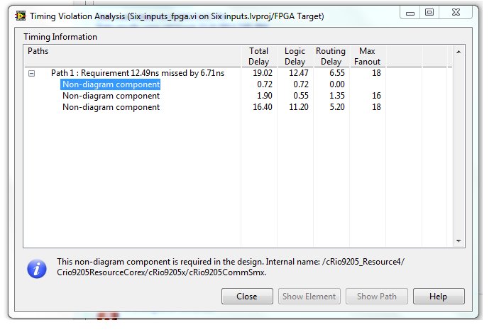
Error of timing in my fpga code
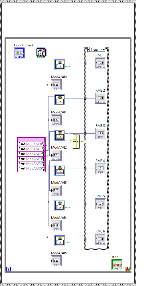
Hello everyone, I have attached an image with which basically indicates an error that I get when I compile my FPGA code. I am also attaching a photo of my code with it. I am a newbie in Labview FPGA and this code might not be effective way to achieve what I'm trying to accomplish. Basically what follows is the application.
I have a sbrio 9642 and I'm six analog inputs and I would get the effective value of these six signals to be as accurate as possible. The entries are pure sinusoids with a frequency of 60 HZ.
If anyone has questions about the code or demand, please post in this discussion. I will try to answer as soon as possible.
Kind regards
Kumar
-
Shipments of electronic mail blocking compactrio
Hello
I have a SBRIO which is supposed to acquire the data and send e-mails in case of alarms.
As soon as the screw of SMTP are managed, the compactrio hangs completely:
-J' have the 'Waiting for connection of pop-up target' when the system tries to send an e-mail.
-CPU usage drops.
What can cause this behavior? Is not a compactrio that is supposed to be able to send e-mail while doing something else?
Best regards
Peper
I had a similar problem in LabVIEW on a PC . LabVIEW would just hang out while sending an e-mail using the built-in functions. NOR ever would confirm it was a bug, but I used a code from someone else posted to make it work. The last message has the code for the example updated the. That's probably essentially what you already have.
-
DIO using loop to generate TTL
Hello
I have a sbRio and on the FPGA, I have a loop that runs every 5 US. The loop has a counter that increments with each iteration, and I acquire analog data each cycle (effectively setting the rate to 200kS/s). The counter is used to generate a Boolean value True or False. Thus, for example, if the count is less than 200 (for example) the value is False, but greater than 200, it's true. The counter then resets back to zero in, say, 400. This counter is used for two purposes - the resulting value of T/F is sent to a DIO port then it becomes, in effect, a TTL output, and because I store the meter with the analog data, it acts as a reference for where the data were sampled in the cycle TTL.
My problem is that when I look at the output "TTL" on an oscilloscope everything seems pretty OK... except that now and then I get a glitch where it suddenly either falls to zero or "stutters".
The question I have is this - if I write a True value for a port DIO in a timed, loop makes this "lock" of value until it is changed or does literally flick on then turned off during a period of time (the implication being that it is actually not a true continuous, but a series of true/false steps which occur on a timescale much shorter than my loop time)? If so, is there a way to make sure the value remains constant until the next iteration of the loop? If this isn't the case, then should I move using ticks rather than at the loop timer?
Thanks (and sorry for the length).
I think the question is read the values half/full cycle. If I replace those with constants, the problem seems to disappear. I moved the reading of those outside the main loop, and that seems to have worked.
Thanks for your help! The loop of the case has been deleted since, as you pointed out, it was not necessary. Oh and sorry for the twisted...
-
Implementation of I2C in FPGA on SOM devkit
Dear all,
I have this sbRIO 9651 SOM with jury of carrier of reference with which I would like to connect a sensor of MPU 6050 Pmod 5 and acquire sensor data in an FPGA VI and process data in a RT VI. I find it difficult to implement I2C interfacing to FPGA as I am relatively new to FPGA programming in LabVIEW. MyRIO implementation was pretty easy as the API and usage example it was easy to access. Any help would be appreciated.
Concerning
Guenoun
Hello
I found this documentation to be very helpful:
https://decibel.NI.com/content/docs/doc-41410
She described the meaning of in, out and activate. SCL clock series, SDA is given in series. In and out are to read and write data, activate switches between being an input or output pin. It is what explains the wiring in this post on the forum: https://decibel.ni.com/content/message/127591#127591
The I2C bus is high when idle, so out is set to false (bass), but this has no effect because enable is false. In order to drive the bus low, enable is set to true. Now has an effect and driving the bus low. If the bottom of the bus is set to true to activate while the output is held low literacy.
I hope this helps you.
Alex
Maybe you are looking for
-
Mail on iPad app not working, not able to access my email to iCloud.
I'm not able to access mail from iCloud. The mail icon shows that I have mail, but when I click on it - it's empty!
-
Hello I seem to have a problem, for which I have already made contact with service to the Netherlands, but all they could do was to advise me to send the walkman to a point of service of the checking, but this is the default response, if they do not
-
Mailboxes of many blackBerry Smartphones - between them...
I have a total of six mailboxes different email (work (Outlook), hotmail, yahoo, aol, blackberry)... in my mailbox, there all messages from mailboxes combined breast and in their Outlook folder (yahoo, aol, etc.). The question is, is it possible to k
-
icons missing for printers and devices on windows 8
Please I need help. I made this statement on this link http://www.SevenForums.com/tutorials/224162-devices-printers-change-device-icons-custom-icons.html all my printers icons now has the same icon and the same information Manufacturer: hp model: hp
-
APEX translation application document
Is there a good documentation (process step by step) for APEX application translations.I'm looking for examples of detailed explanations.Thank youDeepak