Calculate the area under the graph
Hello
I need to calculate the area under the graph, but really have no idea.
Could someone give me an idea please.
Thank you.
I don't know if the example CC attached in this thread will help you or not. Please go through it.
Start your own program. Every time you stuck at anytime, post here. People of genius around the forum here will surely Guide to go further. Do not worry.
Take advantage of wiring.
Mathan
Tags: NI Software
Similar Questions
-
full waveform graph to calculate the area under the curve over time
Hello
If please find my attached VI and help me please for integration to get area undercut for my chart of waveform.
I would like to find my wave power wind energy production chart oever within one month of time.
I think I have to integrate to get the area under the curve and so I m now using tool integrated into labview attached.
As I did not wait years for my result and so I want to make sure that the tool that I m using is correct.
Please advise me what method I will use for my chart.
Dominique says:
I would like to integrate my table of power over time (table of power is on each interval of a minute) and the entire graph is one month. So, I'll put dt = 1?
You put dt at some units you want in the final result. If you want Wh, you want dt in hours. If the spacing is currently a minute, you can express in fractional hours and use the result as dt. Try dt = 1/60.
-
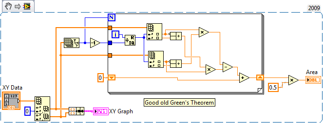
How to calculate the area of a XY graph
I have build a process assessment program and got stuck on it. I have a chart XY of the angles of knee hip x and need to find the area of the plotted curve. I searched the forums, but found no way to do it. Any ideas?
Green theorem comes immediately to mind:
I cut the first two points to make the graph more cyclical and 1300.36 for the answer. That passes the eyeball test, but you should double check my implementation of rapidfire (and my memories of summary calculation).
-
Area of the graph under the graph and not next to the chart legend
Hello
I need to display 1. Graph legend below the graph and not next to the chart area and also reduce the space between the caption box
2. the values in the chart are affiches.1745%, 4.596%... I need to round up these values.
My card code is:
chart:
< graph graphType = 'PIE' depthAngle = '50' depthRadius = '8' pieDepth = "30" pieTilt = "20" seriesEffect = "SE_AUTO_GRADIENT" >
< title text = "Answer category" visible = "true" horizontalAlignment = "CENTER" / >
(< LocalGridData colCount = rowCount="{count(.//G_DT_NON_NA_EQUITY1) '1'}" > "
< RowLabels >
< xsl: xmlns: xsl foreach = "http://www.w3.org/1999/XSL/Transform" select=".//G_DT_NON_NA_EQUITY1" >
< label >
< xsl: value-of select = "SPER_STATUS_TXT10" / >
< / label >
< / xsl: foreach >
< / RowLabels >
< DataValues >
< xsl: xmlns: xsl foreach = "http://www.w3.org/1999/XSL/Transform" select=".//G_DT_NON_NA_EQUITY1" >
< RowData >
< cell >
< xsl: value-of select = "CNT20" / >
< / cell >
< / RowData >
< / xsl: foreach >
< / DataValues >
< / LocalGridData >
< / chart >
I appreciate all the help
best regards and many thanks
Bhavana -
Calculate area under the curve: Hystresis
I have a strength and dispacement of values in excel. I want to calculate the hystresis this.
How can I do this via VBS? I do not have time in that channel, how to create it and find the hystresis?
Rsh
Hi new RSH,
This example is more Visual, but contains about the same content.
In case it helps,
Brad Turpin
Tiara Product Support Engineer
National Instruments
-
How to calculate the signal / noise from the graph?
In my current project, I read a periphera voltage signal. the signal lead noise even after filtering. So, to identify the necessary data, I averaged the signal.
I have attached the file with an image of graphics. In this graph, the recorded data are drawn black and medium online graph is plotted in red. Now, I have to calculate the ratio of signal to noise to specify with these peak values. How to do?
As the signal passes through zero, be careful in the way you set the signal / noise. For sinusoidal signals, that ratio is defined as the RMS value of the noise (the signal with the desired sinusoidal signal deleted) divided by the effective value of sinusoidal component.
First of all I would like to subtract the average value of the raw signal. The difference is the noise. You can set the signal / noise. A RMS calculation might work. If you have a mathematical model for the desired signal, a fitting for this model can be useful too.
Lynn
-
With the mouse to draw the edges of a XY Chart to calculate the perimeter and area of him
I have signals from a stabilometer... I traced X in terms of y in a XY Chart and I want to know how I can draw with the mouse a circle linking most of the points that is the graph of X on Y and calculate the area of her more perimeter. I joined my program labview with two files X and Y
LV 2009 Version attached.
-
Vi transitional measure displayed in the graph of the wave are moving outside the scale
With the help of a graph of a waveform to display the pressure over time. I wanted to be able to calculate the time to drop in pressure over time, so I use the vi transitional measure. I copied what was exactly in the example for the measurement of transition inside help and it is correctly determine when to transition down, but I'm having a problem with the cursors in waveform graph. I would like to see a set of greenery along the fall time start and end time of fall as pictured, I have attached the vertical sliders (capture2) as in the example. The problem is the two always begin to 3.43 (capture1) and after each sampling period they (4.34, 5.34, 6.34) increment him come right out of all of the output of transition as these numbers measure. The period of the signal that I am interested is always less than 2 seconds, so I never see the vertical sliders.
I tried replacing it by my signal daq with an sine wave signal generator and it does the same thing.
The block diagram is in the first capture
also, I would be interested to know exactly how the numbers wired to the cursor property active of the property of a waveform graph node toward real sliders on the chart. They are just automatically numbered starting at 0 from the top down?
Wayland
Hi Wayland,
The sliders are still apparent in the example VI for the transitional Measurement.vi, is because the generated signal is always set to zero. Thus, signal resets a 'new' signal for the sliders to move and therefore always on the same location a bit. The waveform graph is also configured so that it won't move or continue to show new incoming data, data sliders have moved on. So in your case, you want to click with the right button on the chart and make sure that "Ignore Time Stamp" is not checked/selected. This will make it so the graph continues with your incoming data and cursors. You can check it in the example file by removing the constant True is the generator of signals and change the mentioned time stamp option previously.
In order to view the available sliders as well as their position numbered, you can right-click in the waveform graph and select Properties. In the Properties window, there is a tab of cursors, inside this tab at the top is a drop-down menu that lists all available sliders, indexed starting with 0 at the top.
-Jake B.
-
With regard to the area under the curve of ROCK - ODM
What method is used by Oracle Data Miner to calculate the area under Curve (AUC) of ROCK? trapezoidal or other? Please answer me
It's a discreet trapezoidal approximation focused exclusively on the shift points.
-
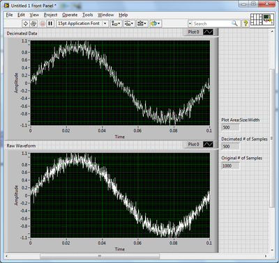
How the graph data are resampled pixels?
A test, I created two identical graphs with land areas 500 pixels wide and a noisy sinusoidal signal of 1000 samples. A chart displays the waveform right, while the other got the results of the use of the function Arrray to decimate to halve the number of samples. They are not the same.
Up to a waveform graph does exactly when it displays a data value larger than its width in pixels?
As you have noticed, the graph is a little more intelligent that you expected. When the number of points exceeds the number of pixels, a form any resampling must take place. A simple decimation as you tried would eventually pass some interesting points. Instead, the outliers receive priority when selecting which points to display. Strong in this way, peaks and dips appear even on a large scale. Reproduce this behavior yourself can be tricky. And once you reduce the data set, the points are gone and zoom is not as effective.
Usually, I try to let the chart to do as much as possible. A simple and effective way to reduce the size of the data you have to ship on the network is to use the SGL precision instead of double precision.
-
Variation of thermocouples (+ - 2 ° C) and are under the same conditions
Hi, my English is not the best but I trust in your intuition and intelligence capacity.
Actually Im connecting many thermocouples (type J) in a DAQ 9213. I managed to take all measures (7 thermocouples) and also the thermocouples are calibrated. My problem is that the 3 thermocuples give me one 20 ° c (60F) and the other 4 give me 22 ° c = 71.6 ° F, and all the thermocouples are under the same environmental conditions. The easy solution is to put an offset and compensate for the error but it is not a good solution.
Can someone tell me what is happening? I think it's wiring problem maybe the COM, but I've referenced the negative signal (low signal) to the COM, also tried not to referencing the negative signals to the commune, but the result is worse because the signals are going crazy.
Please help me, please!
Hi Jesus Hernandez
Also remember that the thermocouples have a positive and a negative side, so if you plug wrong temperature will be different and it will decrease rather than increase when something warmer so close.
Best regards
Julio Mena
-
How to ensure that the graph xy plots are present?
Hello community,
Since the update to LabVIEW 2014 this week, I have a problem with the code that worked (or didn't, but the problem was unnoticable).
As example the llb I created to present the question, I'm graphic xy filling with quiete some data and then color programmatically plots.
The problem is that if there are too many plots then the property nodes that are to color the mistakes of Mr. thow plots as if the corresponding plots were not present in the graph still - even if I used a single flat sequence structure to try to ensure that the data is written in the plot before trying their color.
Maybe this wouldn't be in LabVIEW 2013 too - but the threshold for the number of plots was higher. All I can say is that I have observed this with data sets that worked well in 2013 of LabVIEW.
To reproduce simply run 'color of the graphs.vi' with values high enough to 'numerisch' and ' numerisch 2 "(50 on my machine can be more about yours).» I left the terminal nodes property unwired error so you get caught up in the right position when the error occurs.

Somehow check if all parcels are in the charts again? This way I could introduce a delay that ensures that I don't have the color of the graphics that do not exist yet - regardless of the speed of the target computer.
Xy graph behavior has changed in 2014 of LabVIEW? Or maybe his performance?
Best regards
Florian
HM, your addendum somehow answered my question. We are indeed an against the user interface thread race condition.
Unfortunately, I do not know a method to wait than the UI thread to have access to all plots. In addition, the waiting time that you need depends on the ability of the system, which is dynamic, you know not all processes background or in parallel, running applications.
That being said, I recommend a work around:
1. create the data for the plots
2. how many plots you have in query data
3 write short dummy data in the terminal, and not the data of the whole plot
4 Recolor plots
5. write the correct field data
Norbert
-
Graphics of APEX with Flash gives error error e/s in the graph area
Hello
The user gets the IO error in the chart area. It uses version 11 of the Internet Explorer browser. Here is the screenshot of the error in the chart area:

And the user has Flash player installed. The environment that we have is oracle apex 4.2 version with apex listener.
Any ideas what may be causing the problem?
Thank you
MK
Hello
Thank you! for your answers...
Brad & pleNn,
The graph was made on our machines and machines of the user of the client unless a user...
Since it is the user's machine, we cannot debug APEX...
As part of the troubleshooting in the user's computer:
Checked the control panel > add or remove programs found that has been installed Flash player and Shockwave player is not installed, but, when looked at Internet settings explore > addon I've seen Shockwave Flashobject is present which makes the table and it shows active... So, it was a little confusing and I thought that the Shockwave Player must be installed and
I told the user to do things below and it WORKED like a charm...
- Uninstall Flash player
- Reinstall Internet Explorer
- Install the latest version of Flash player from the Adobe Web site
- Install the latest version of Shockwave player from the Adobe Web site
Thank you
MK
-
I need a file to an exact width and height and it must be in png format, because it allows to translucency. My graphics are only the top of the page and when I export only the graph is not exported the entire file. How can I get the entire file of export including blank parts?
in the export dialog box, you have chcked 'use of work plans? ''
-
How to calculate the area of shapes in Illustrator CC2015
Is it possible to find / calculate the area of an irregular shape in Illustrator CC2015? I ' v read everything I could find on the internet - with no luck. All tips refer to older versions of Illustrator...
This script looks very good. can't imagine that it could be broken in CC2015.
Script to find the domain of the forms in Adobe Illustrator
will need adjustment if you devices other than the thumb

Maybe you are looking for
-
Hello my daughter here Forgot password for iPod and know is turn off, can you guys help me please?
-
Save the Page (Ctrl + S) used to open a small window of the Explorer (Windows 7 OS). All of a sudden (after update for FireFox 37.0.1), it opens a window of browser enlarged (full screen). The passage of the mouse on the window edge, arrows a size ch
-
The upgrade to 50 GB renews each month. Or you can use the 50 GB as long as you need and cancel the upgrade after the month.
-
Not good with 2 recovery cd recovery OS?
During an installation of audiocatalyst, I have a problem with, and then the entire system failed not woork correctly. Especially could not watch the monitor for 4 to 6 minutes more and you get headaches and the eyes are tears to shed. Then I start t
-
you have a call saying theres a problem with my computer
microsoft Windows contact people by phone to tell them of problems