cDAQ several chassis
I use multiple cDAQ chassis on a network. Is it better to create a separate for each chassis DAQmx task or combine in 1 great task?
I have not tested with multiple cDAQ chassis, but there are a lot of cards PCI/PXI which even let not you have a task to cross several cards.
In my opinion, I would use separate tasks for each chassis. Makes it a bit more modular code.
Tags: NI Software
Similar Questions
-
How many quadrature encoders may be read together with the cDAQ-9188 chassis?
We will record position periodically 8 engines (at the same time as we are to the corresponding samples entered analog). It seems that the 4 built-in counters limited chassis to 4 encoders. Is this correct? I am familiar with modules of counter PLC which manage high-speed counting, and then the CPU posts periodically to update the total values. This is how the NI 9401 card would work?
Hi jtrout,
You are right the 4 built-in counters than the cDAQ-9188 chassis 4 encoders. The following article deals with the use of the NI 9401 card for encoder measures: http://www.ni.com/tutorial/7109/en/.
-
Generate a pulse train, NI 9402 modules in cDAQ-9174 chassis
I have two modules NI 9402 in a cDAQ-9174 chassis.
When I output a pulse train on a specific line of the PFI to a specific module, the pulse train is out on the right line of PFI, but on BOTH modules.
I want that the pulse train out only one of the modules.
for example, I select cDAQ2Mod1/ctr1 to output a pulse train on PFI3 of module one. I hear the pulse module one PFI3 train, but I also get it on PFI3 of module 2.
I am also a measurement of separation of two edges with a different counter, but I don't seem to have this problem. (The measure only works when I have the signals connected to the module that I've specified.)
-Paul
This is the Vi I work with.

Hmmm... Looks like it's actually only after I exit a signal on that line. Maybe I should try to clear the line.
-Paul
-
Bad analog output help Every_N_Samples-NI-9263 cDAQ-9172 chassis (works with cDAQ-9178 chassis)
Hello
The NOR-9263 analog output voltage geberation works correctly with the cDAQ-9178 chassis but gives wrong result using the chassis NOR cDAQ-9172.
In the attached code example, a single cycle of a sine wave is composed of 40000 samples and came out in the background using Every_N_Samples at a rate of production of 5000 samples per second.
The output buffer size is set to 10000 samples.
Prepare us the buffer writing 10000 samples 1, then write the remaining data in the background using the Every_N_Samples callback.
Bug: Using the cDAQ-9172 chassis, to the 5000 s/s sampling rate with the help of an external field (or through closure to another HAVE), we observed that 1 10000 samples came out twice, followed by the rest of the waveform. The last 10000 samples are never exits. If you are working properly, we would expect to see 1 full cycle of a sine wave.The bug does not occur with the chassis NOR cDAQ-9178. I use the driver NIDAQmx v9.2.1f0 on Windows XP
The bug does not happen with simulation devices, so you will need to use harwdare real to reproduce.Please find attached an example of code C based on the example program OR "ContGen - IntClk.c" to reproduce this bug.
Thank you
whemdan,
The MathWorks
Hi whemdan,
By default, DAQmx regenerate old samples if no new data is available. To give the correct behavior, you can:
Use DAQmxSetWriteRegenMode to disable the regeneration (DAQmx_Val_DoNotAllowRegen). In most cases, this is recommended if new data are written continuously in the buffer as the build is in progress.
If you just need to generate 40 k samples, you can write them just all at once, rather than in 10 pieces of k (the code you attached probably is just an example, so I'll assume that you have a reason to write the data into segments in your actual code).
I think the difference in behavior between 9172 and 9178 can if explained by the different way, buffering is set up on each product. The 9172 uses a buffer of 8 k (on the STC2) in all cases (source). The 9178 uses an 8 k of memory buffer (on the STC3) If you use regeneration shipped, but uses the 127 samples FIFO cartridge, if you use no on-board regeneration (source).
Then... on the 9172 8191 samples are immediately transferred to the FIFO. By default, the hardware is going to request new data when the FIFO is less to fill (this is configurable with DAQmxSetAODataXferReqCond). I'm not sure what the transfer data request size is in your case (you can set the maximum value with DAQmxSetAOUsbXferReqSize), but obviously it is bigger than the other 1809 samples that you have not yet sent to the Board of Directors of your first entry. At this point, the pilot will regenerate 10 existing k samples so that sufficient data will be available to meet the demand of data transfer.
The 9178 however use the FIFO of 127 smaller samples so you will not have the same behavior in your case.
In summary, the behavior is explainable by the difference of material. If you want to avoid to regenerate old samples, you should ban the regeneration using DAQmxSetWriteRegenMode.
Best regards
-
new cDAQ-9178 chassis was smaller than the cDAQ-9172 old buffer?
Digital waveform features:
Waveform acquisition (DI) FIFO for cDAQ-9172: 2047 samples
Waveform acquisition (DI) FIFO for cDAQ-9178: 127 samples per slot
This means that the new HW (9178) has a much smaller than the old buffer (9172)!
I want to run a correlation over generation/acquisition at 2 MHz with 2000 samples. Does this mean that the new chassis will not be able to acquire the whole of the data (I use a NI 9401 module inside the chassis)?
FIFO sizes are misleading and not a true indicator of the chassis supporting the streaming is not the single buffer. We did some tests comparing the latest and cDAQ-9172 chassis. You will not notice the difference, especially with your application to a finished task of 2 000 samples at 2 MHz. With 2 000 samples, you can run your DI task on your chassis cDAQ-9178 at 10 MHz if you wanted without problem (don't try with continuous or even finished tasks).
The only time where the FIFO size really comes into play is when you run a primary task at high rates, say > 5 MHz, even if it is system dependent. At these speeds a FIFO that is deeper 2 000 samples you buy only tens or hundreds of additional microseconds when Windows jitter is measured in milliseconds.
I would be very surprised if there is a practical application that worked on a cDAQ-9172 chassis which did not work on newer USB cDAQ chassis.
-
cDAQ9172 said that the Earth correctly (page 15, Fig. 6) user guide the chassis:
"attached a leg of the ring to gauge AWG 14 wire. Connect the leg of the ring to the Terminal on the side of the cahssis screws from land. Connect the other end of the cable to the Earth of the system security.
So I connected the leg of the ring to the ground on the side of 9172 screw. Can someone show me where should I attached the other end of this cable to found the chassis correctly?
Thank you very much!
If you use a cable with shielding, also of the shield of protection must be linked to the earth so that it is truly effective. Connect the shield at the end of the cDAQ should suffice. Please note that the shield of the cable is different from the + and - connections in a cable. If you use a 9234 BNC connectors, it is likely that you have not also shield you must connect. Most of the time, shield wire is twisted cables.
-
Is it possible to route signals of relaxation between two chassis PXI-1002 with the PXI-8335?
Hello
as the subject says, I am interested in the delivery of a signal to trigger between two chassis PXI-1002. At present, these two chassis are connected by a MXI - 3 system using maps PXI-8335. The software is Labview 2010 sp1 and 380 NIScope drivers.
We want to keep (a PXI-5122 by chassis) scanners supply separated due to the requirements of our measure! The chassis are connected via cable to fiber optic. This explains why I can not just use the shutter release in Star, or connect via 'Trigger' or 'clk' cards (the inputs / outputs to the front of the cards).
I found a few examples, but they seem to all be designed for use with a chassis only, I'll call later to the examples that inspired me to this point. Each guide explaining the synchronization of several chassis systems seems to use another material or VI is not accesible to me. This makes me wonder if my hardware has the capacibilities I need.
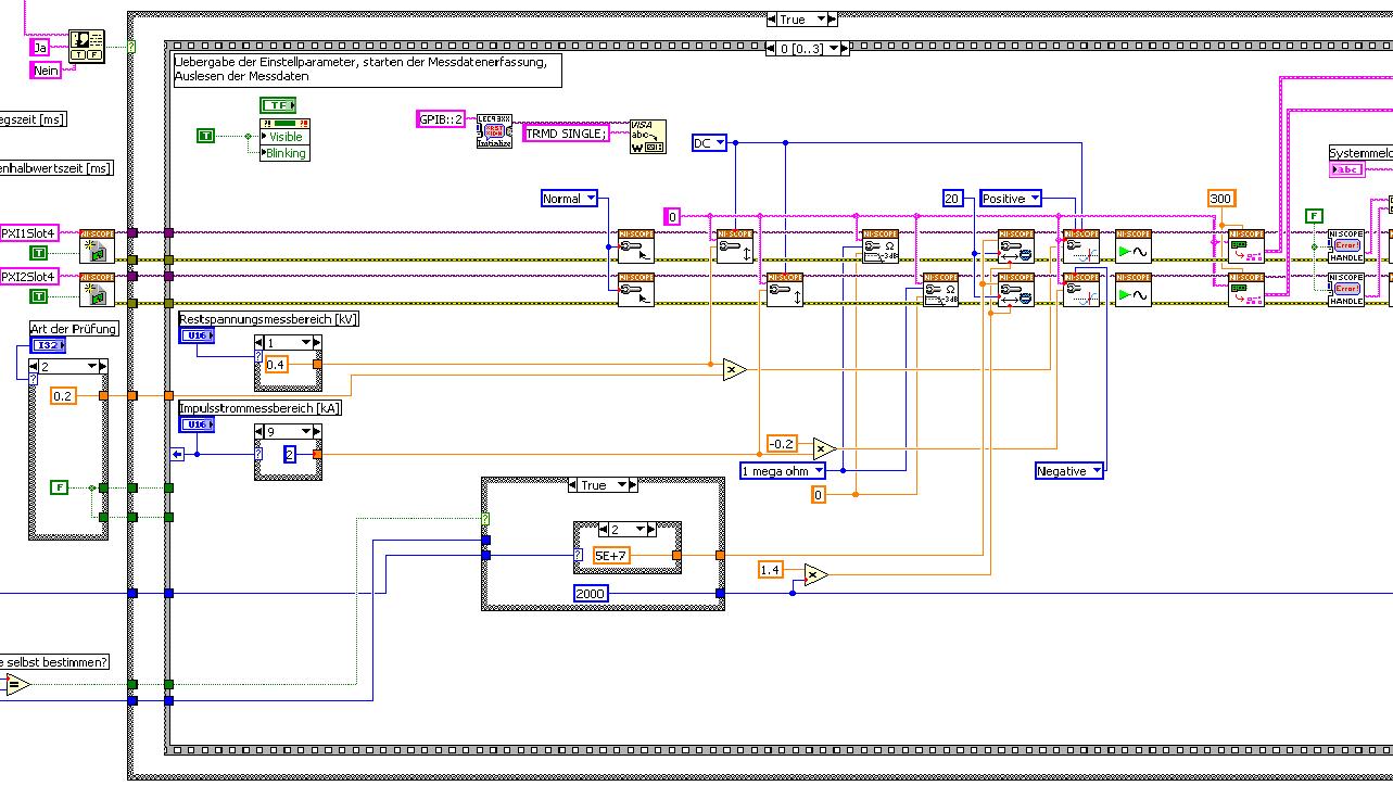
The first picture shows approximately where I started from (sorry I can't post VI, confidential...):
Only the middle part is interesting. Two sessions are initialized and manipulated parallel, trigger too. This has led to delays in the signals and should now be fixed. This apart from the VI works fine.
Goal is to trigger only on one channel but both devices! If possible, the device will trigger must be chooseable.
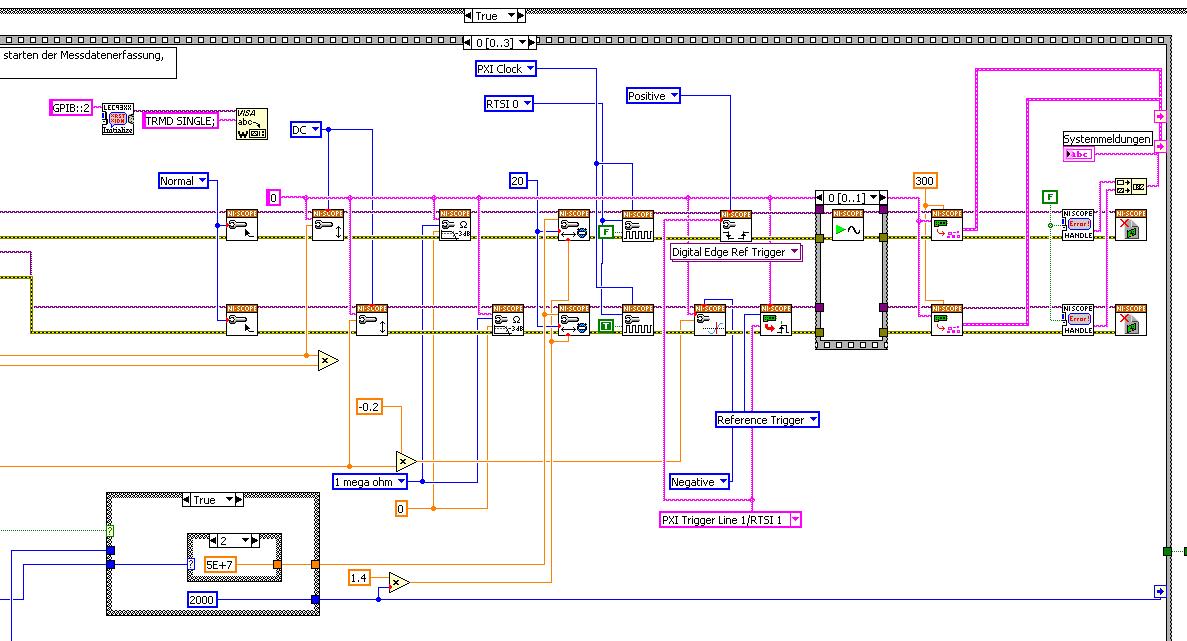
I started to rebuild the VI using the "EX Synchronization.vi 5xxx niScope' seeming spontaneity. The result is shown in the following image:
I tried different RTSI lines, but had no positive results. only the main channel has triggered.
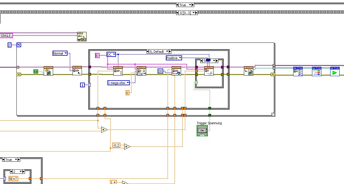
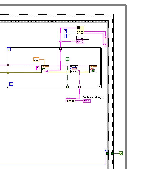
After this first approach, I looked in the "niScope EX .vi multi-Device configured Acquisition (TClk)" and other examples of TClk which seem to work for similar problems. The VI of reconstruction can be seen in the following images:
(Sorry, I had to use two photos..)
In this case, I didn't have no choice for trigger lines, it would automatically set the VI TClk. I tried to trigger on both devices, though. This second approach seemed promising to me, but it was an error:
"niTClk Synchronize.vi:1".
Index (starting at zero) of the session: 1
The error reported by the pilot of the instrument:
No registered trigger could be found between the
devices on the route.If you have a PXI chassis, the chassis correctly identify in
MAX and make sure that it has been configured correctly. If you use PCI
devices, make sure they are connected with a RTSI cable and that the cable RTSI
is saved to the MAX. Otherwise, make sure that there is an available trigger line
the trigger bus shared between devices.Source device: PXI1Slot4
Target unit: PXI2Slot4
Status code:-89125niTClk Synchronize.vi:1
Index (starting at zero) of the session: 1
The error reported by the pilot of the instrument:
No registered trigger could be found between the
devices on the route.If you have a PXI chassis, the chassis correctly identify in
MAX and make sure that it has been configured correctly. If you use PCI
devices, make sure they are connected with a RTSI cable and that the cable RTSI
is saved to the MAX. Otherwise, make sure that there is an available trigger line
the trigger bus shared between devices.Source device: PXI1Slot4
Target unit: PXI2Slot4
"Status code:-89125"
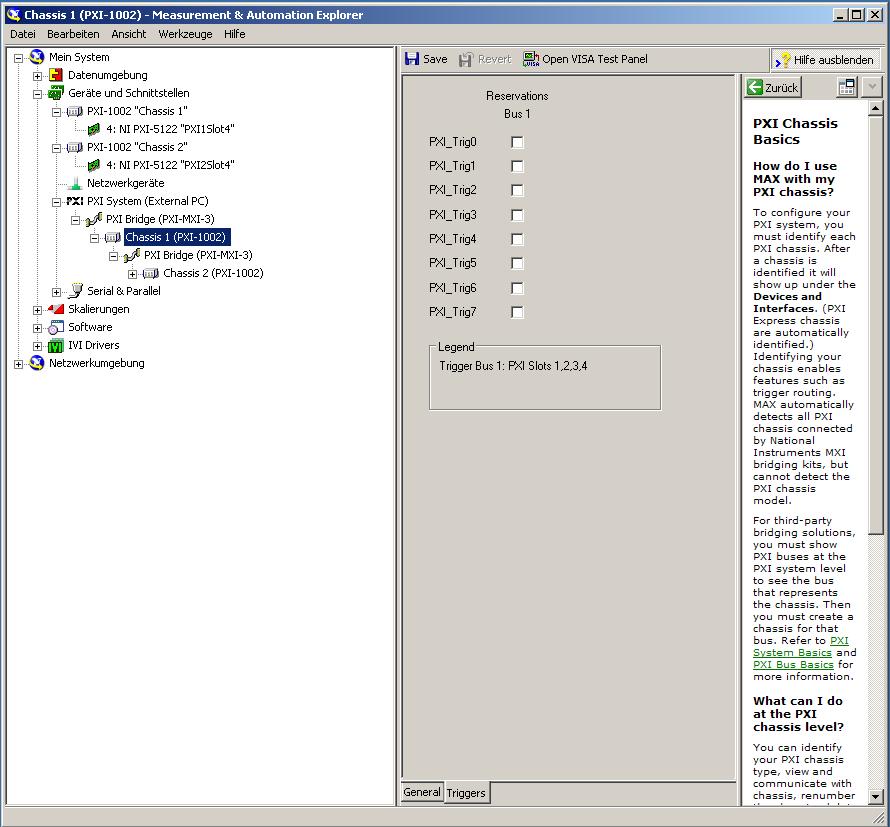
This error came back even after I've identified this drug as possible to the MAX, as shown in the screenshot:
In some of the textbooks, they showed how to get the MAX trigger lines, but as you can see, there is only booking options in my MAX. Whatever I do, I can't find options to define how to get my trigger signals...
In principle, it is possible to trigger instruments in different chassis, which is indicated in this Guide and others... the question that remains is can it be done with my set of components?
I understand that the use of multichassis compromised the integrity of the lines very adjusted as trigger in Star etc., so the configuration should be taken into account in some way, that my approach does not, I knew... But there must be a way to do this? And to start: to get just any signal from one device to the other trigger!
For any advice on this issue, I would be very thanfull!
Concerning
Max1744
Hi Max,.
Thanks for the detailed post and explanations of your application and requirements. You're right using TClk, because this is the optimal method to synchronize the 5122 digitizers. The original VI you worked with is unique for some of the legacy scanners and does not directly work with scanners based on the most recent CMS (for example the 5122). The good news is that you can synchronize these cards to separate chassis, but it will use the calendar 66xx and synchronization (T & S) cards in the chassis of the master and the slave, as indicated in the guide that you have accessed. These are needed because a common reference clock must be shared between them as well as a couple of tripping. MXI itself can not handle export triggers and clocks, so there is no way to do this without physically wiring between the chassis with cards T & S. Unfortunately, regardless of what specific method, you use for synchronization, it will take a material extra beyond what you currently have.
As one of your needs looks like it is necessary to retain wiring between the chassis directly, you may need to consider to synchronize using 1588 or GPS protocols. 1588 Protocol is a system for synchronization on the network while GPS course use antennas and locks for a common wireless signal. Although these synchronization methods may allow you to keep your chassis isolated, they will also require some manual configuration because you would be able to use the TClk synchronization and so the level of synchronization you can get between the cards may not be as good that can physically wire signals between the chassis using T & S cards.
Hope this helps,
-
cDAQ HAVE task using external clock
Hi, I am trying to use a clock signal on a line of PFI in order to generate a clock, but at a lower rate, for a task to HAVE. I run into many issues that I can't explain.
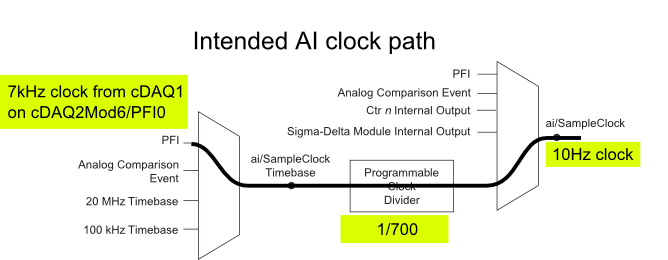
I have a cDAQ-9172 with an entrance module analog (9225) in the Groove 3 and a digital input module (9411 - 2 MHz DI) into the slot 6 (where the PFI lines are accessible). I want to use an external signal on et0/PFI0 to act as the clock for an analog input on the 9225 task. This signal comes from the cDAQ anothr chassis and is too fast for the task to HAVE it, so I intend to use the time base entrance and the divider to clock (as shown on page 31 of the cDAQ-9172 manual). See picture attached for a graphical representation of my problem.
If I have the wiring from the signal "/ cDAQ2Mod6/PFI0" in the DAQmx timing VI, get the error 200414 saying that "required sample clock source is not valid." It is strange because it is listed as "Direct route" in Max (the VI of polymorphic DAQmx Timing is configured as 'Sample clock') Q: why this route is not suitable for the task?
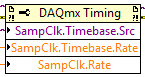
If I use DAQmx Timing property node and change the Source 'Sample clock Timebase' to ' / cDAQ2Mod6/PFI0 ", the task starts without error, but the separation seems to be forced to 256. If I try to change the properties of the separation of the time base, I get error-201100. Try to change the 'sample clock rate"doesn't have any impact on the task and the remains of divider"256 ". Q: why the 'Programmable clock divider"locked to 256 when using the PFI line or can you just not program directly?
I came across another error is the minimum speed on the PFI line. If I have the wiring (for the SamplClock Timebase) lower at 1 MHz, LabVIEW returns error-200077. The error message indicates that the minimum value is 1 MHz. 9172 manual shows the clock 100 kHz is an option for the time base, certainly less than 1 MHz. Q: What are the limits of upper and lower frequency for a clock signal on the line PFI for the ' Timebase AI/SampleClock "?
I looked on the site and in the DAQmx documentation for further explanation, but I have been unable to explain these strange behaviors. What are the barriers to entry of Timebase PFI and the time base "Programmable clock divider" preventing me to reach my goal here? If I can't do it directly, can I use the PFIn signal to feed an internal counter (to act as the clock divider) which could then generate the clock WAS at the rate I want? This method would allow me to perform a division arbitrary clock (unlike the ' 256', which seems to be forced on the PFI as a Timebase SampleClock.)
Finally, something seems odd that I can make an acquisition to 10Sa/s max but when I start a task using an internal timers of the cDAQ9172 and ask a 10Sa/s rate, the task really gives me a rate of 1612.9 sample/s while using the 12.8 MHz clock and a divider 7936 timebase. Q: Why can't the task to 10Sa/s?
I use DAQmx 9.7.0 and LV2012 SP1 (and I tried with 9.7.5 but I got the same results)
Thank you
Olivier
I got additional help Friday in another engineer at NEITHER and the solution to my original problem is actually very simple to get the clock from an external source path:
The idea of picking a PFI line for the basis of 'time' and the 'Programmable clock divider"(in fact, DAQmx calculate this number based on"HAVE sample time clock"and"Sample clock HAVE") works by using the node property below:
(SampleClock.Source cannot be resolved until the task is clerks/reserved, but the default option seems to be the time base that works well in this case.)
The question that I described earlier with the 9225 comes the module properties and the fact that it is a "Module of Sigma - Delta". That the module usually generates its own time of 12.8 MHz base clock (page 14 of the document 9225 # 374707) and the clock divisor is much less possible values than the other modules (must be a multiple of 256). It may use a different time basis from a PFI line, but it must be between 1 MHz and 13.15 MHz.
So a main clock between two chassis and tasks running at different rates of sharing should be easy and simple with most of the modules. With AI modules with Sigma-Delta converters add additional limitations and the master clock for the time base frequency must be selected to accommodate these module as well.
Another good news is that the Simulator seems to bear all these details and DAQmx (9.7.0 in my case) generates the same errors when you use a simulated chassis if you use real body. Play well!
-
The transition of the cDAQ to cDAQ ENET USB
Hello community,
For some reason, I'd probably change some of the cDAQ USB chassis that I use for the Ethernet frame cDAQ base. I already have some applications developed on the platform of the USB and I was wondering how painful (or even at all) migration from USB to Ethernet. I guess also assign an IP address to the chassis and set it up in MAX, it should be relatively easy.
It would be nice to know about problems I can cope.
Thank you.
As far as I saw, just that everything is set up in MAX, and then it is homogeneous in all of your applications. You may need to remove all instances of your USB cDAQ located in MAX in order to reuse the virtual name.
-
synchronize 2 cDAQ-9215 modules on the cDAQ-9174
Hello
We collect 8 channels of the AI of the comments about 32KS/s, but they must be synchronized with precision. We intend to use 2 CDAQ-9215 modules mounted on a CDAQ-9174 chassis. This system will do the job? And what kind of calendar and clock configuration should I use to improve the precision of the synchronization.
Thank you.
Hello
I'm sorry I didn't know not the 9215 was a simultaneous module. Instead of the S series card, you should be good to go with a 9174 and 2 9215 modules. If you use the same DAQmx task to run on all 8 channels acquisition they share all the same timing engine and snack at the same time.
-
Synchronize the pci-6254 and cDAQ-9174
Dear all,
I hope you enjoy!
I intend to synchronize two cDAQ-9174 chassis for an application where I need to acquire data of 8-Thermocouple, voltage 3, 1-Full bridge (strain gauge) and channel 2-meter at the same time. This enforcement action is based encoder (quadrature with 1024 ticks per round) and I need to acquire data very fast and synchronized in all channels!
I bought the material and I'm going to set up 3-voltage channels in NOR-9221, Thermocouples-4-NOR-9211, 1 strain of NOR-9237 and 2-meter gauge in NOR-9401 first cDAQ-9174 chassis Modules. I will then put remaining Thermocouples-4 in the second cDAQ-9174 chassis.
The question is whether it will work?
If Yes! Then, kindly help me on how to have synchronized it data from these two cDAQ-9174 chassis with all such modules as mentioned above?
I hope someone can help me with that and can guide me to do this task! I'm using Labview 2009 with NOR-DAQmx 2009
Kind regards!
Tajim!
A few comments after looking at your code:
I don't understand what you're doing with cancel in the task of counter.
You try to use the encoder as your sample clock? You can do it for the module 9221 and NI 9211, but it will not work with the NI 9237 as I mentioned above. You can move the NI 9237 in a separate task and from there, you have a few options depending on how you want to synchronize.
How many times you expect to get your clock on cDAQ2Mod3/PFI0?
-
Hello
I'm working on a project that requires two outputs digital signals at different frequencies. Frequency of the phase 1 is about 1 kHz and is modulated on and off to a pace that will change during the execution of the program. Wave 2 passes from 1 kHz to about 6 kHz while needing to be pretty accurate to the tenth of a Hertz.
Initially, I tried to manage the simultaneous output of signals at different frequencies using a single task on a single 9477 daqmx in a cdaq-9174 chassis. As far as I know, the best way to get a specific frequency in a waveform output is to set the sampling frequency up to 2 times the frequency of the wave that is generated and generate a waveform that is given to each clock cycle. This works very well when it comes to a gesture, but I was unable to get the frequency of the modulated wave (wave 1) remains constant when the frequency of wave 2 modified or vice versa.
I have a few other modules lying around (another 9477, 9403 and 9476) and I thought I would try another task running on a separate module. I find myself receive error-50103 message if I add these modules to my cdaq chassis and run one of the waveforms of a task set to run on the add-on. Is there a way to bypass this error? I guess it would cause by running two digital output on the cdaq-9174 tasks at the same time, but it seems to me that this wouldn't be a problem with an additional module.
How can I have two outputs digital signals, running at the same time, maintaining their independent frequency frequency of the clock of the other sampling rate changes. In addition, because the wave 1 is enabled and disabled at a defined frequency, I use it to set the number of samples to write when you write a range of waveforms in the module (when generating these two waveforms on the same module).
I'm sorry if the explanation was difficult to understand. I've attached an example of error 50103 lifting. This isn't really a part of my project as a whole, but it is the easiest way to reproduce the error.
Thank you
Hi awol.
I have a follow up for you. You encounter the error because the cDAQ chassis has only a timing engine of. You will not be able to perform simultaneous tasks of the call by the hardware. Please see the following knowledge base: http://digital.ni.com/public.nsf/allkb/5E0B829E50ADE1BC86257AC50062B2D2
Mike
-
Hello
I need to measure the deformation of 3 gauges (each gauge acquire strain of 3 directions).
I would like to know if I could use 3 NI 9219 unit on a frame?
Because I tried to use 2 capture card and I get an error! I have to use only one piece of advice!
Thank you
Simulating a cDAQ-9174 chassis with 3 modules MAX NOR cDAQ-9219 does not generate an error so I would say that Yes, it is possible.
To make sure, I highly recommend contacting your local service of NOR.
Kind regards, Jens
-
Module AO trigger using PFI on the cDAQ-9188
I use a cDAQ-9188 chassis with an AO (NOR-9264) module. Is it possible to configure a PFI (channel on the frame) as an input signal to synchronize an AO channel with the trigger? Here's what I'm trying to do. I need a channel on the AO module to switch voltages in sync with the trigger when the user "push a button". So once the button is pressed, the channel of the AO will not change until the next trigger pulse.
Thanks for your help
Ben
Hello Ben
I hope you are well. The consensus is that it is possible. Have you tried this yet? If so, can you tell me what you have tried and how you made a lot of progress? I recommend the following VI example: Cont Gen tension Wfm - Ext Clk.vi. Are you able to get all the functionality you are looking for this VI. It was recommended that I'm showing you this. We find this VI under help--> find examples and then material input output &--> DAQmx-->--> voltage analog generation.
Please let me know how you are progressing and if you have need of all aspects of this example explained. Thanks for choosing National instruments!
Sincerely,
Greg S.
-
The cDAQ-9134 USER1 play button
Hi all
My idea is to use the User1 on the cDAQ-9134 chassis to start recording.
How to read this button in my VI (Windows)?
Many thanks in advance,
Thomas
Hello tom1757
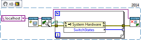
I don't have the material at the moment. You can change the seal snipped for only
read you the 9134 material switchstates.
I hope this helps
Maybe you are looking for
-
I can't print my gmails of Firefox, but I can print them in Safari.
I tried all the options listed in the troubleshooting supportinformation, and I still cannot print from gmail. Should I have any more options?
-
Satellite C850 - PCI Simple Communications Controller
I just bought this new C850 Satellite but with no OS on it, then I installed windows 7 ultimate x 64 and all the drivers but in my device manager there is an unknown device its called controller PCI of communication Simpleand its hardware ID arePCI\V
-
Original title: upgrading an earlier version of Windows Media Player If I want to move my old windows media player, must I first uninstall the old version and delete its program files?
-
Hi, I have 5 Vostro 220 s. motherboards computer parts are: 0P301D. I want to upgrade from processors. Can you recommend the most powerful CPU (socket LGA 775), for this model? 0P301D will support Core 2 Quad 9550 or higher? Thanks in advance.
-
How can I get rid of what looks like a soccer ball on the screen?
When I move the cursor upwards or downwards, a small icon that looks like a soccer ball that appears on the screen and its function is to scroll the screen at lightning speed. It brings me to tears. How can I get rid of him?