Conduct and variation LED with USB-6501
I have a bunch of LEDs connected to a power supply with an intermediate dimmer. The specifications for all this material is listed below. I'm looking to move from manual control to digital I/o. I have an NI USB-6501 data acquisition, but have never worked with her before and so would like some tips. The goal is to maintain a maximum brightness, but be able to fade the lights of my software. I read several threads on simple power control but that you did not find anything on the gradation.
John.
Lights: (red)
Drive:
Power source: (15 Watts)
http://www.superbrightleds.com/moreinfo/power-supplies/12VDC-CPS-series-power-supply/68/
In order to control something, you must be able to physically connect the 6501, but it does not appear that have anything to connect to. The image of the drive, it has just one button.
Tags: NI Hardware
Similar Questions
-
Too low current performance with USB-6501
For my measure I connected to an output port (output high voltage, 28 pins) with resistor of 10kOhm to ground (Pin 32). For the active reader to type out in car, I measured a 3.33V voltage and current of 0.33mA. I repeated the same measure with open-drain configuration, which leads to 3.27V and 0.33mA. I use NI-DAQmx and changed the disc type of output with a property node in labview 8.5.1. High-voltage output was generated with labview. In a second step, I put out high voltage with the able Control Panel & automation of DAQmx which led to the same result.
For my measure I'd wait a current higher return especially for active training mode, since the specification indicates a voltage between 2.8 and 3.6V for 2mA. I don't understand why the output current is not 0.5mA which would lead to 5V.
If I do the same measure with the + 5V output (PIN 31) source instead of the output port (pin 28), the current is as expected 0.5mA and 4.8V power can be measured.
For all measurements, I used a NI USB-6501 which has already been tested by an engineer from the Canadian standard.
Hello James Mc.
Thanks much for the reply. To reach the CMOS specifications (between 3.5 and 5 v) I add an external pull-up resistance and use to open-drain output ports.
Kind regards
Priska Studer
-
Trouble with USB-6501 with Labview 8.6 Pro for Mac OS
Hello
I have a unit USB-6501 I try to use with Labview 8.6 for Mac Pro to processor intel.
I have the driver NOR-DAQmx base 3.2 for Mac installed and when I ran "Isdaq", it detects the device and also warned that the firmware needs to be updated. So, I ran the "FWUpdate" for updating the firmware. I double check the Isdaq and it detects the device as "NI USB-6501:"Dev1"(USB0::0x3923:0x718A:014386 B 0: RAW).
Now, when I run Labview 8.6 and DAQmx Base create channel VI and the port of 'physical' wire to the control, nothing appears in the available device.
Also, when I run the mxbaseconfig program, not the existing basic tasks detect the device.
Could someone please help me get this to work? Basically, I need to read and write slow digital data through USB-6501. But, the Labview does not detect the device.
Thank you
Keong,
I do not know what causes this, but place a task create VI before your code and the wire of the output task to the task of entering the chain and try to run that. Please let me know if it works for you.
-
NI USB - 6501 OEM more sensitive to electromagnetic interference?
We built a NI USB-6501 OEM card in a small instrument of office dedicated to switch ultrasonic impulses 300V between 3 transducers, using reed relays not shielded high-voltage controlled by the USB-6501 (using MOSFET transistors to drive the relay coils). The end user reported that when he operated his ultrasonic transmitter at greater than 100 v voltages, USB-6501 would break (green "heartbeat" ceases, LabView or test panels lose communication with the interface). Lower voltages to ultrasonic had no effect. Inspection of the 5vdc supply rails when running the pulse generator showed ears LOUD noise (surprise?), so we have recreated the box so that 1) optical isolation and no electrical connection between the USB-6501 and switching and 2) pension switching was surrounded by a 'box in the box '. During a test, ultrasonic signals apparently still radiation enough so that the USB-6501 would break as before.
Avoiding half measures, I mounted the USB-6501 in a completely separate extruded aluminum case (the land to the USB bus, but not to "taking" of land) with optical transmitters and optical fiber plastic 3' has been the only connection to the ultrasonic switch box (which is inside its own extruded aluminum case).
This made things better: the USB-6501 would work for a while when the ultrasonic signals were present but still crashes after a few minutes. In addition, reports researcher that starting the engine w / controller in immediate proximity to this interface also immediately causes a crash of the USB-6501.
Right now I do more optical cables and confirmed that the USB-6501 works thankfully when he is simply the engine optical transmitters with no ultrasonic signals in the area. I'm surprised that this digital i/o interface seems so sensitive to environmental disturbances.
We made sure that 1) was based on the shield of the cable USB ONLY at the end of the PC, according to the specification USB; 2) cable USB was of ferrite chokes to make it less
an antenna 'noise' 3 the Board 6501 had connected logic ground the housing in aluminium, and 4) we have equipped the case with a pattern important
cable and clamp to connect to a 'true' of the Earth.
When the end user has reported that there were still problems, I went to his lab and discovered
He assumes that hang on a couple of wires ground wire, to a strain gauge, which was stuck on a piece of 3' of the railway, itself sitting on a wooden table
no electricity whatsoever, what meant it was "founded". After that I am makes me sputter and him look staring in disbelief, we plugged into an electrical conduit nearby,
and all of a sudden, the problem disappeared.
I'm glad it works now, but the fact that turn on an instrument of motor stepper located three feet of 6501 can crash against interference if)
the case is not grounded), stillsurprises me. I expect to use 6501 in other instruments, it will take extra precautions on the armor.
-
Hello
I have a USB-6501.
When I send the value True to the writing DAQmx digital VI the signal from the equipment turns off, and when I wire a false material passes.
The same thing happens with an entry. Causes a short circuit between the terminals and ground out the fake DAQmx for read, and unconnected with this is true.
A colleague has the same problem with the 6501, but not with its PCI DAQ card.
It is somewhat paradoxical when programming. Is there a way to reverse this behavior? (other than just not forgetting to add in one does not)
Simple test VI attached.
Phil_ wrote:
Tested with a different usb-6501 on another machine. Same problem...
If your work Apok ok, so it's really weird.
Would you care to elaborate on the above Apok?
My knowledge of electronics is minimal
your IO is linked to a 4.7Kohm resistance which is also connected to 5Vdc. transistor is turned off, output pulls up to the level of 5Vdc and... output transistor pulls up close gnd, given a drop of transmitter led
-
USB-6008, USB-6501 and Embarcadero C++
Hello NEITHER and NOR users,.
I spent a considerable amount of money several years ago on a number of devices USB-6008 and USB-6501 for a class that I teach on interfacing the simulations with realworld sensors and actuators. Write us code using Embarcadero C ++ Builder and we wrote the code to interface with the jury of EZIO AD / DA via RS - 232. The EZIO is much too slow and limited. Given advertising NOR, we bought these boards, but after several attempts to get some information OR on the way to talk to these devices directly via C++, we have yet no valid response. No, I don't want to LabView or any additional expenses. I just want to talk to them directly.
OR: are you ready to help with this, or not? If this is not the case, although wanting to refund these purchases. Announce as being accessible from C++, but you are not willing to provide any help of substance to this day...
Yes, I am self-taught, write code, and old-school enough to feel that I have a right to know how to talk to all the devices I buy. I confess my ignorance, but I'm sick and tired of secret corporate and misleading advertising.
Can someone please provide me with enough example of code to start. That's what we wrote for the EZIO:
http://www.Duke.edu/Web/ISIS/Gessler/Borland/RealWorld-Ezio.htm
We would like to start writing similar code for these materials of NEITHER. If possible, we can buy more. If this is not the case, these cards are useless.
Kind regards
Nick
Nicholas Gessler, PhD.
Nick,
When you have installed the DAQmx drivers to communicate with the 6008 and 6501, I assume you also installed programming examples? It is here that they are on my XP machine: C:\Documents and Settings\All Users\Documents\National Instruments\NI-DAQ\Examples\DAQmx ANSI C. I don't think that Embarcadero C++ Builder is one of the languages supported, so you'll need to twist your compiler, but it should give you a good start.
Tom
-
USB-6501 and opto-coupler SFH615A
Hello
I'm driving an opto-coupler (Siemens SFH615A - spec link attached) using the USB-6501. I am really a beginner and I am looking
help on how I can connect it. I have tried a few options already but no luck.
http://docs-Europe.Electrocomponents.com/WebDocs/009C/0900766b8009c194.PDF
I use a Servo-Drive in a project, a motor drive. Unfortuantely USB-6501 turns out logically lines high on the servo-controller startup is
receipt of a signal. I hope I can pass the INHIBITION of the servo drive line, through the opto-Coupler, so when you start 6501 will cause the optocoupler
circuit close to inauguration of the line inhibit preventing displacement engine. The labview program will make the logic of the bass line to allow the engine to move.
Looking at the manual of the USB-6501 and previous questions, there are 2 ways to do this, but working on resistance, values etc. required is
still a bit beyond me, and unfortunately I'm a bit stuck for the moment.
Any help would be greatly appreciated, thank you.
OK got it works, I hope it will be useful for others.
My problem, I think, have no idea really, is the impedance of the I/O device. Despite everything, I used a buffer of gain of the unit with the help of the
Intersil ICL7611 powered by the + 5V line with the line of digital output connected the + IN the axis of the ICL7611. On the output, I have a
Resistance 120 ohm before the opto SFH615A. Opto is open beginning 6501 and high but closed low logic logic. Happy days until the
the next problem happens

-
How do I turn on/off outputs multiples with a single button using USB-6501 & Labview 2010
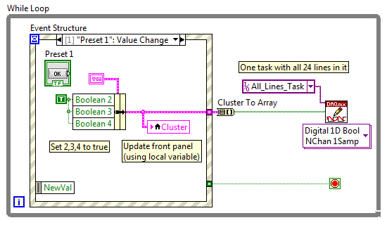
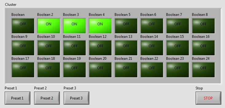
I've written a VI with 24 buttons, one for each output of the USB-6501, for turning on and off 24 relay. Now, I want to add more buttons that activate and deactivate the outputs multiple. We will call these Presets buttons and pressing the Preset button a few outings turn and some turn off. Get it? The VI I've included a screen shot is used to test a transmission controller and rather than to manually select one at a time relay I want a preset button that sets up instantly relays for the next stage of the event.
The VI I wrote uses tasks created in NI MAX.
I am a beginner of Labview, so please try to keep your easy to understand solutions if possible.
Thank you
Kevin
BTW, I'm registered in Core 1 and 2 month next to Richardson, Texas.
Here's an example - you will learn about the grapes, berries, events, etc., in the class, but this will give you a head start. Code is attached but I took a screenshot to give people an idea of how simple the schema becomes:
As your learn about them, I suggest you also make the cluster a TypeDef and make management mistakes, but I've omitted the example to keep things as simple as I could.
Good luck, LabVIEW learning, it is worth!
~ Simon
-
Timed signal generation TTL with the NI USB-6501 to be read by Arduino Uno
First of all, I want to apologize - I am very, very new to LabVIEW and brand new to the development of the software of control equipment in general. I tried to find an answer to this question already, but I'm not entirely sure what I'm looking for.
I have currently a work program LabVIEW which operates a gun card NI USB-6501. Due to the nature of having a machine that springs from a powerful beam of electrons, we want to assure you that if the computer controlling stalls or fails for any reason, we have built-in security that can stop the gun. Our current idea is to connect an Arduino Uno on a PIN on the USB-6501 and LabVIEW to generate a timed signal, which may read the Arduino. If the signal fails (indicating that the control computer has queued or off), the Arduino triggers a power relay that is independent of the control computer and turns off the gun.
I understand that the USB-6501 operates on TTL signals, so the signal that I should be something in the sense of "output TTL high, wait 1 second, output low expectations, a second, repeat TTL ', but I have no idea how to go about programming in LabVIEW. My first thought was that it is a square wave by using the function "simulate the signal" output, or to have trigger an iterative Boolean signal, by using the function 'DAQmx write', but I don't really understand how do to implement or another idea, or if an idea would even work.
Any advice would be greatly appreciated.
Hi Elizabeth,.
THINK THE STREAM!
When do you DATAFLOW think everything falls in places!

Several problems:
-You have to put that MAKE impulse VI in his own loop parallel to your main VI!
-When you place this generation of impulses in the effects loop ("TTL arduino low-high") you should put the CreateTask and StopTask outside the loop: no need to create/stop the task in each iteration.
-Why are there points of constraint to waiting functions?
-Why is there bent wires? You know Ctrl-U?
-LabVIEW comes with an extensive library of example screws: you looked at all these examples DAQmx?
-Suggestion: Learn more about the "structures of producer-consumer"!
-
How to generate a continuous ttl signal with a USB-6501
Hello everyone,
I am a beginner with LabView, so maybe my problem, it's very easy to fix.
I need to generate a digital output using a USB-6501. This TTL signal will then switch to a device. Basically, I need the digital output to be permanently to TTL high level until a user active departure is given. Then the digital output must stay to the TTL low level until another stop active user is given.
Does anyone have any suggestions on how to do? I have failed so far to get something different high TTL to my USB 6501.
Thank you very much.
Hi there, take a look at the VI I enclose. You can find more information about the device in textbooks and on this forum. I hope this helps
-
Update firmware for USB-6501 with 3.4.0 driver?
Hello
I am wanting to use the 3.4.0 NI DAQ driver with a USB-6501 and finds that the firmware is incompatible with the driver. The most recent driver that I used was the basic driver 2.1, unfortunately, the software that I use to send signals to the USB-6501 requires libraries to the 3.4.0 pilot.
Y at - it a firmware available that is compatible with the 3.4.0 driver DAQ for USB-6501 device?
I see that, after you have improved your DAQmx Base 2.1 to 3.4.0 drivers he said that the firmware on the USB-6501 is incompatible.
If you go through this knowledge base, it will show you exactly how to get the firmware compatible with DAQmx Base 3.4.0. In particular, near the bottom, it shows how to perform this update.
-
I have an imac 27 "... on power there is no signal to startap, usb ports are not working and its deadlock with the logo of the Apple with the circle of rotation... Help, please
Wake the computer to your Apple store or Apple authorized service for the service provider. He probably suffered a hardware failure.
-
Got a 27 "monitor from Apple, with thunderbolt (error). My MacPro can't love at first sight. Apple won't bring back the monitor. Will using a USB 3 map and then using a hard drive with USB 3 and Thunderbolt works?
N ° you need a computer logic board which has built in Thunderbolt.
-
External Usb Audio Card Popping and cracking sound with Satellite L500
Greetings,
My name is Boyan and I am from Bulgaria, and a year ago, I bought a laptop satellite l500 series (I can't tell which is exactly the model at the moment because my computer is not currently with me and my user manual, the only thing that is said is that it is for L505/L500/L500D / L505D.) But from memory I think it was the Satellite L500D-ST5506 which is currently not at my dispossal, because I gave him for repairs for the same problem that I say down below)
The problem with my laptop, is that when I plug in a Usb Audio card in my laptop I have a crackling sound during live sound is played hollow map external speakers/headphones. I tried several sound cards and speakers/headpohnes which work perfectly well with other computers, including laptops, but the problem continues even when I use an external sound card to connect to the laptop not appearing in my laptop speakers/headphones.
The problem is important only when the signal passes through an external audio card and it is very disruptive since I use my laptop to create music and I bought a sound card expenssive and speakers that can not be used with the laptop. I tried 3 types of sound cards:
M-Audio Fast Track Pro
BEHRINGER uca 222
and a simple 3d audio usb audio card external and the problem persists.
At first, I thought that the problem is software and I should install the new drivers, windows 7 automatically recognizes and installs the drivers for the devices and I have its in (but with the cracks and educated) so I tried using the official drivers sold for me with the sound cards, but without success: the problem was still there. I tried to find the new drivers of the sound cards on long official distributors and I downloaded it but the problem was still there. Then I tried to delete all the audio drivers on my computer and just use the external sound card for sound but this eighter helps force. I updated my drivers for my sound card build - in as well but again - no luck.
After substantial thing frist I did when (2 weeks after I bought the laptop) was to contact the store where I bought my audio card and they said that the problem may be so eighter latency or high voltage of the laptop they advised me to try to reduce the latency of the parameters or to try and see if the problem persists if only my laptop running on battery power. I tried two things, and they did not help. Audio cards worked without problems on all the other computers I tried them but me. So they told me that the problem could not be audio cards.
What I then was that I gave my laptop for the Distributor official of toshiba in my country so that they can solve my problem. What they told me, is that a problem with the version of windows which was preinstalled on my laptop and it was not compitable with the sound cards (which was bizzar survey because I tried them on the same windows and they worked, only on other computers). So I'm back from my laptop and passed under my Windows 7 Home Premium 64 bit operating system to Windows 7 Ultimate edition 64-bit and Windows 7 32-bit Ultimate edition on all versions, that's the problem: whenever I activate a low of passes of audio signal and Audio Usb card he heard cracks and educated. I even tried isntalling Windows XP, but the laptop want spesific SATA drivers for the Windows XP installation which although I found - they helped me install XP and I didn't go the BIOS of the computer to try to put a new and so on, because I'm not sure about that and I could lose my warranty so I said in the official repair shop for Toshiba in my city to put XP on my computer to solve the problem but they can't because they are not liscened to work with software that isn't a recipt for its purchase (which I did not because I bought my windows xp a long time ago and I lost the recipt)
I gave her to get it repaired for the second time by telling them that the change of my operating system has not solved my problem and what they were doing was they changed the motherboard on my computer, indicating that the build in the device realtek audio on my computer is good enough to support a card usb audio or it may be broken and they change the whole motherboard because the generation of card is stuck, so they did it, but my problem has not been resolved. They told me that although I use and map external audio usb signal always going trough my only internal and I have to disable so I tried to disable this trough Control Panel, but this does not solve the problem and I don't have a BIOS option to disable my sound card build-in. Another thing I thought that maybe the problem is that two audio cards do not work on the same bitrate and Hertz so I put both cards to 16 bit 48000 Hz DVD quality (also tried the other options on the 3 cards that I have) but it's the same thing.
They told me that it's just my luck and the construction of the sound card does not support this external sound cards and I would had been more careful when they choose to my laptop first.
I couldn't accept this awnser for several reasons:
(1) this sound card works on a lower version of windows and are supported by many older models of Realtek and a lot of old computers (one of them bought 2000! and my laptop is of 2010!)
(2) the guys who were the apperantley of fixing problem don't go so deeply into my problem because they didn't know that in fact the problem was that only they knew that there is a problem with the audio card and the computer interact with them, they knew not that it cracks during the direct play the external audio card.
(3) I can't accept the fact that Toshiba is manufacturing of models with maps audio chipset that cannot support a simple external Usb Audio card. It is totally unacceptable to me, and I sincerely hope that this is not the case!
(4) they have tried my audiocards on another laptop of the same series, claiming that they have not at their dispossal at the moment so I'll go tomorrow at a local store and try the sound cards by myself on the same computer in the store.
What I have now, it was that I gave my laptop for repair requesting a statement of the problem in wrtting with details of the problem so I can go to court or ask for a new laptop, but I'll be charged with little money because according to them there is no problem in the laptop and the problem is that my external sound cards are not compitable with the build in house chipset sound card. If I give my laptop for repair, and there is no hardware problem, I'll have to pay the money. I will do this, but I'm now crazy, because that does not solve my problem and I am wasting time and money.
What I ask here is, if you can not help me solve my problem and advice me what to do to fix it, please give me the details of the chipset built in Driver sound card on my motherboard, so I can check if it is compitable with my external sound cards and contact the dealers of the sound card to ask them their opinion. Or if you can tell me what it is compitable with and what not, that would be great. Personally, I think this laptop should have no problem at all with a simple external usb running sound card, but I ask you, if you know something more about it.
If a problem with the build in chipset then Toshiba is manufacturing (or at least sell) audiocards which are not in a normal standart but unfortunately I can not do nothing except complain to Toshiba and never treat whith such productgs more. Otherwise, if this is not true, then my laptop has a problem that is different and I have to go to court with the mans for mounting repair is not my laptop or do not give a new one when I guarantee will not fault of Toshiba and it will be in a way solve my problem.
I hope that you understand how important it is for me and I hope I have fix the problem as soon as possible.
P.S
I want to say that I am familiar with grammar mistakes, that I did in the text below, and I would ask your excuses that I'm not a native speaker of English.
Hi, I would just say that I had a similar failure although I wouldn't be surprised if she causing of yours, but you never have knowledge, my fault was the lid of my laptop [9 months], it contains the mic and when the lid has been in a certain angle cracks could be heard worse when I got my external sound card all the time it happened, luck, PS, it's a defective membrane [lid to the body] easily missed by engineer because he was the same angle you English is very good
Post edited by: sido1
-
Clock and hw external trigger with USB-6210 on Linux with NOR-DAQmx Base?
I have two devices USB-6210 I need to synchronize so that they both collect data exactly at the same time. I was told by support OR I can send the clock off Dev1/PFI4 and have the two USB-6210 s read the clock in through their own PFI0. I also want to trigger data collected for each device by sending a trigger off Dev1/PFI6 and have two devices to receive the signal on PFI2.
All my attempts to try this are filled with error messages and my research online seem to say that's not possible with USB devices on NOR-DAQmx Base 3.4.0f2 on Linux.
I "ve tried using example AI programs and those who do not seem to work either for external clocks. Here is the code I tried:
#include "NIDAQmxBase.h"#include

#define DAQmxErrChk(functionCall) { if( DAQmxFailed(error=(functionCall)) ) { goto Error; } }

int main(void){    // Task parameters    int32       error = 0;    TaskHandle  taskHandle = 0;    char        errBuff[2048]={'\0'};    int32       i;

    // Channel parameters    char        chan[] = "Dev1/ai0";    float64     min = -10.0;    float64     max = 10.0;

    // Timing parameters    char        clockSource[] = "/Dev1/PFI7";    uInt64      samplesPerChan = 1000;    float64     sampleRate = 10000.0;

    // Data read parameters    #define     bufferSize (uInt32)1000    float64     data[bufferSize];    int32       pointsToRead = bufferSize;    int32       pointsRead;    float64     timeout = 10.0;

printf("Calling CreateTask...\n");    DAQmxErrChk (DAQmxBaseCreateTask("",&taskHandle));printf("Calling CreateAIVoltageChan...\n");    DAQmxErrChk (DAQmxBaseCreateAIVoltageChan(taskHandle,chan,"",DAQmx_Val_Cfg_Default,min,max,DAQmx_Val_Volts,NULL));printf("Calling CfgSampleClkTiming...\n");    DAQmxErrChk (DAQmxBaseCfgSampClkTiming(taskHandle,clockSource,sampleRate,DAQmx_Val_Rising,DAQmx_Val_FiniteSamps,samplesPerChan));printf("Calling StartTask...\n");    DAQmxErrChk (DAQmxBaseStartTask(taskHandle));printf("Calling ReadAnalogF64\n");    DAQmxErrChk (DAQmxBaseReadAnalogF64(taskHandle,pointsToRead,timeout,DAQmx_Val_GroupByChannel,data,bufferSize,&pointsRead,NULL));

    printf ("Acquired %d samples\n", pointsRead);

    // Just print out the first 10 points    for (i = 0; i < 10; ++i)        printf ("data[%d] = %f\n", i, data[i]);

Error:    if( DAQmxFailed(error) )        DAQmxBaseGetExtendedErrorInfo(errBuff,2048);    if(taskHandle != 0) {        DAQmxBaseStopTask (taskHandle);        DAQmxBaseClearTask (taskHandle);    }    if( DAQmxFailed(error) )       printf ("DAQmxBase Error %d: %s\n", error, errBuff);    return 0;}
When I run the resulting program, I see this:
$. / acquireNScans-ExtClk
The CreateTask call...
Call for CreateAIVoltageChan...
Call for CfgSampleClkTiming...
Error-89136 DAQmxBase:route specified cannot be satisfied, because the hardware does not support it. For example, a clock and a trigger can be imported via one of the PFI lines by using a USB-6210 on Linux with NOR-DAQmx Base? A clock and a trigger exportable via one of the PFI lines?
If so, does anyone have the code example illustrating how to do this, or can you at least tell me the names of the lines ("PFI0/Dev1" or other) so I can try again?
Clues or suggestions would be helpful.
Thank you
-Tom
The clockSource in the example specifies an output rather than an input channel channel. Change source "/ Dev1 / PFI0" solved the problem.
Please close this post.
Maybe you are looking for
-
How do the average of the last 5 values of a column as new values automatically entered?
If the issue is not clear for you, here's a site I found that teaches you how do it on excel. ml https://www.extendoffice.com/documents/Excel/2533-Excel-average-last-5-values.HT I can't find the corresponding method on the good numbers. Thank you
-
How recovery C00D10D1: DivX MPEG - 4 (DX50)
Windows Media can not read the CD and the DVD. error C00D10D1: DivX MPEG - 4 (DX50). How to recovery that?
-
I can't get my computer to turn on. the screen remains black. The power button lights up and stays on, he can't stop. I have it pluged in, it is not currently running on the battery. I still have it pluged, never used on battery. Have a fan cooling
-
TransformGestureEvent.GESTURE_SWIPE
I am trying to capture a general call and have not been able to. Here is the code: public class MySwipeTest extends Sprite { public function MySwipeTest() { var myLabel:Label = new Label(); myLabel.text = "swipe this"; addChild(myLabel); myLabel.add
-
Problems with Skype message saying 'a problem caused blocking the program works correctly.
Original title: Programs Application Applications Apps game games Legacy Crash crashes Hang Application Compatibility hangs Skype problems... message appears saying... A problem caused the blocking of the program works correctly. Windows will close