USB-6501 and opto-coupler SFH615A
Hello
I'm driving an opto-coupler (Siemens SFH615A - spec link attached) using the USB-6501. I am really a beginner and I am looking
help on how I can connect it. I have tried a few options already but no luck.
http://docs-Europe.Electrocomponents.com/WebDocs/009C/0900766b8009c194.PDF
I use a Servo-Drive in a project, a motor drive. Unfortuantely USB-6501 turns out logically lines high on the servo-controller startup is
receipt of a signal. I hope I can pass the INHIBITION of the servo drive line, through the opto-Coupler, so when you start 6501 will cause the optocoupler
circuit close to inauguration of the line inhibit preventing displacement engine. The labview program will make the logic of the bass line to allow the engine to move.
Looking at the manual of the USB-6501 and previous questions, there are 2 ways to do this, but working on resistance, values etc. required is
still a bit beyond me, and unfortunately I'm a bit stuck for the moment.
Any help would be greatly appreciated, thank you.
OK got it works, I hope it will be useful for others.
My problem, I think, have no idea really, is the impedance of the I/O device. Despite everything, I used a buffer of gain of the unit with the help of the
Intersil ICL7611 powered by the + 5V line with the line of digital output connected the + IN the axis of the ICL7611. On the output, I have a
Resistance 120 ohm before the opto SFH615A. Opto is open beginning 6501 and high but closed low logic logic. Happy days until the
the next problem happens
Tags: NI Hardware
Similar Questions
-
USB-6008, USB-6501 and Embarcadero C++
Hello NEITHER and NOR users,.
I spent a considerable amount of money several years ago on a number of devices USB-6008 and USB-6501 for a class that I teach on interfacing the simulations with realworld sensors and actuators. Write us code using Embarcadero C ++ Builder and we wrote the code to interface with the jury of EZIO AD / DA via RS - 232. The EZIO is much too slow and limited. Given advertising NOR, we bought these boards, but after several attempts to get some information OR on the way to talk to these devices directly via C++, we have yet no valid response. No, I don't want to LabView or any additional expenses. I just want to talk to them directly.
OR: are you ready to help with this, or not? If this is not the case, although wanting to refund these purchases. Announce as being accessible from C++, but you are not willing to provide any help of substance to this day...
Yes, I am self-taught, write code, and old-school enough to feel that I have a right to know how to talk to all the devices I buy. I confess my ignorance, but I'm sick and tired of secret corporate and misleading advertising.
Can someone please provide me with enough example of code to start. That's what we wrote for the EZIO:
http://www.Duke.edu/Web/ISIS/Gessler/Borland/RealWorld-Ezio.htm
We would like to start writing similar code for these materials of NEITHER. If possible, we can buy more. If this is not the case, these cards are useless.
Kind regards
Nick
Nicholas Gessler, PhD.
Nick,
When you have installed the DAQmx drivers to communicate with the 6008 and 6501, I assume you also installed programming examples? It is here that they are on my XP machine: C:\Documents and Settings\All Users\Documents\National Instruments\NI-DAQ\Examples\DAQmx ANSI C. I don't think that Embarcadero C++ Builder is one of the languages supported, so you'll need to twist your compiler, but it should give you a good start.
Tom
-
Hi all
Is it possible to directly connect a 4N35 to a line?
THX,
C.
Most often optocouplers are driven with an open collector output, USB6501 specifications say that the outputs are configurable open-collector configuration. You can connect to the (LED) entry of the 4N35 directly to the digital release of USB6501, the cathode must be connected to the output terminal and the anode to + 5 VDC (ground with the pilot circuit) via a current limiting resistor which limits the output current to the 8.5mA that can be managed by the USB6501. The calculation should be based on the minimum voltage swing, the voltage is maximum + 5V and the minimum of tension is the tension of saturation of the USB6501 (0.8V) the direct voltage LED (approximately 1.2 v), the output voltage swing is so 3.0VDC.
You can also connect the anode of the contribution of 4N35 directly to the output of the USB6501 Terminal and use the push-pull configuration. The cathode must be connected to the MASS of the output USB6501 circuit. In this case, the current limit strength calculation must be based on
-the maximum output current (8.5mA)
-the minimum output voltage @ 8.5mA (2.0V) less the direct voltage (1.2V) LED.
He must also know what you want to drive with the 4N35. The current transfer coefficient is about 40 p.c. @ 10mA current forward. If = 8.5mA it is a little higher, but do not expect a maximum output of more than 3 transistor current processing capacity, 5mA. If you need a higher output current, you need to use a buffer circuit.
-
NI USB - 6501 OEM more sensitive to electromagnetic interference?
We built a NI USB-6501 OEM card in a small instrument of office dedicated to switch ultrasonic impulses 300V between 3 transducers, using reed relays not shielded high-voltage controlled by the USB-6501 (using MOSFET transistors to drive the relay coils). The end user reported that when he operated his ultrasonic transmitter at greater than 100 v voltages, USB-6501 would break (green "heartbeat" ceases, LabView or test panels lose communication with the interface). Lower voltages to ultrasonic had no effect. Inspection of the 5vdc supply rails when running the pulse generator showed ears LOUD noise (surprise?), so we have recreated the box so that 1) optical isolation and no electrical connection between the USB-6501 and switching and 2) pension switching was surrounded by a 'box in the box '. During a test, ultrasonic signals apparently still radiation enough so that the USB-6501 would break as before.
Avoiding half measures, I mounted the USB-6501 in a completely separate extruded aluminum case (the land to the USB bus, but not to "taking" of land) with optical transmitters and optical fiber plastic 3' has been the only connection to the ultrasonic switch box (which is inside its own extruded aluminum case).
This made things better: the USB-6501 would work for a while when the ultrasonic signals were present but still crashes after a few minutes. In addition, reports researcher that starting the engine w / controller in immediate proximity to this interface also immediately causes a crash of the USB-6501.
Right now I do more optical cables and confirmed that the USB-6501 works thankfully when he is simply the engine optical transmitters with no ultrasonic signals in the area. I'm surprised that this digital i/o interface seems so sensitive to environmental disturbances.
We made sure that 1) was based on the shield of the cable USB ONLY at the end of the PC, according to the specification USB; 2) cable USB was of ferrite chokes to make it less
an antenna 'noise' 3 the Board 6501 had connected logic ground the housing in aluminium, and 4) we have equipped the case with a pattern important
cable and clamp to connect to a 'true' of the Earth.
When the end user has reported that there were still problems, I went to his lab and discovered
He assumes that hang on a couple of wires ground wire, to a strain gauge, which was stuck on a piece of 3' of the railway, itself sitting on a wooden table
no electricity whatsoever, what meant it was "founded". After that I am makes me sputter and him look staring in disbelief, we plugged into an electrical conduit nearby,
and all of a sudden, the problem disappeared.
I'm glad it works now, but the fact that turn on an instrument of motor stepper located three feet of 6501 can crash against interference if)
the case is not grounded), stillsurprises me. I expect to use 6501 in other instruments, it will take extra precautions on the armor.
-
Hi all
I have a brand new NI USB-6501, and I'm looking for more help with the operation. I'm running OS X 10.11.1, LabVIEW 2013 SP 1, NI-VISA 15.0 and NOR-DAQmx Base 15.0.0. I set up and plugged my module and get the flashing green light stable. I ran NI MAX, found the module and renamed 'Motor_Module '. Then, I went to my DAQmx Base of examples and found the Control.llb Interactive USB-6501 and ran the interactive VI control that is contained in this library.
The first thing I tried was simply running the VI. I got error-200220, device ID is not valid. I changed the name of the device to "Motor_Module" and run the VI. This time, I got error-200558, a task cannot contain multiple independent devices. Create a task for each independent device.
And here I am. My ultimate goal is to have this output module signal collector type open to + 5 V. Any help would be greatly appreciated. Thank you.
Hi Sullivnc,
I would recommend you look at a few examples in the Finder for example of OR. Under input and output hardware, there is a folder for DAQmx who has a record for a digital output which has some useful examples. If you do continuous or left over, you can add more stuff to your code as a clear task DAQmx, vi DAQmx Timing, and/or vi DAQmx task is made.
-
Timed signal generation TTL with the NI USB-6501 to be read by Arduino Uno
First of all, I want to apologize - I am very, very new to LabVIEW and brand new to the development of the software of control equipment in general. I tried to find an answer to this question already, but I'm not entirely sure what I'm looking for.
I have currently a work program LabVIEW which operates a gun card NI USB-6501. Due to the nature of having a machine that springs from a powerful beam of electrons, we want to assure you that if the computer controlling stalls or fails for any reason, we have built-in security that can stop the gun. Our current idea is to connect an Arduino Uno on a PIN on the USB-6501 and LabVIEW to generate a timed signal, which may read the Arduino. If the signal fails (indicating that the control computer has queued or off), the Arduino triggers a power relay that is independent of the control computer and turns off the gun.
I understand that the USB-6501 operates on TTL signals, so the signal that I should be something in the sense of "output TTL high, wait 1 second, output low expectations, a second, repeat TTL ', but I have no idea how to go about programming in LabVIEW. My first thought was that it is a square wave by using the function "simulate the signal" output, or to have trigger an iterative Boolean signal, by using the function 'DAQmx write', but I don't really understand how do to implement or another idea, or if an idea would even work.
Any advice would be greatly appreciated.
Hi Elizabeth,.
THINK THE STREAM!
When do you DATAFLOW think everything falls in places!

Several problems:
-You have to put that MAKE impulse VI in his own loop parallel to your main VI!
-When you place this generation of impulses in the effects loop ("TTL arduino low-high") you should put the CreateTask and StopTask outside the loop: no need to create/stop the task in each iteration.
-Why are there points of constraint to waiting functions?
-Why is there bent wires? You know Ctrl-U?
-LabVIEW comes with an extensive library of example screws: you looked at all these examples DAQmx?
-Suggestion: Learn more about the "structures of producer-consumer"!
-
Update firmware for USB-6501 with 3.4.0 driver?
Hello
I am wanting to use the 3.4.0 NI DAQ driver with a USB-6501 and finds that the firmware is incompatible with the driver. The most recent driver that I used was the basic driver 2.1, unfortunately, the software that I use to send signals to the USB-6501 requires libraries to the 3.4.0 pilot.
Y at - it a firmware available that is compatible with the 3.4.0 driver DAQ for USB-6501 device?
I see that, after you have improved your DAQmx Base 2.1 to 3.4.0 drivers he said that the firmware on the USB-6501 is incompatible.
If you go through this knowledge base, it will show you exactly how to get the firmware compatible with DAQmx Base 3.4.0. In particular, near the bottom, it shows how to perform this update.
-
Conduct and variation LED with USB-6501
I have a bunch of LEDs connected to a power supply with an intermediate dimmer. The specifications for all this material is listed below. I'm looking to move from manual control to digital I/o. I have an NI USB-6501 data acquisition, but have never worked with her before and so would like some tips. The goal is to maintain a maximum brightness, but be able to fade the lights of my software. I read several threads on simple power control but that you did not find anything on the gradation.
John.
Lights: (red)
Drive:
Power source: (15 Watts)
http://www.superbrightleds.com/moreinfo/power-supplies/12VDC-CPS-series-power-supply/68/
In order to control something, you must be able to physically connect the 6501, but it does not appear that have anything to connect to. The image of the drive, it has just one button.
-
Hello
I have a USB-6501.
When I send the value True to the writing DAQmx digital VI the signal from the equipment turns off, and when I wire a false material passes.
The same thing happens with an entry. Causes a short circuit between the terminals and ground out the fake DAQmx for read, and unconnected with this is true.
A colleague has the same problem with the 6501, but not with its PCI DAQ card.
It is somewhat paradoxical when programming. Is there a way to reverse this behavior? (other than just not forgetting to add in one does not)
Simple test VI attached.
Phil_ wrote:
Tested with a different usb-6501 on another machine. Same problem...
If your work Apok ok, so it's really weird.
Would you care to elaborate on the above Apok?
My knowledge of electronics is minimal
your IO is linked to a 4.7Kohm resistance which is also connected to 5Vdc. transistor is turned off, output pulls up to the level of 5Vdc and... output transistor pulls up close gnd, given a drop of transmitter led
-
Type of output USB 6501 digital IO
Hi, I'm new to this software.
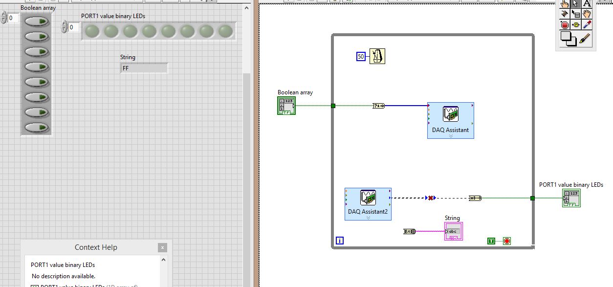
I use an e/s digital NI USB-6501 24 lines.
I physically wired PIN0.7:0 to PIN1.7:0, then all PORT0 go to PORT1
Click these buttons to table of Boolean, to set the output levels of PORT0, then having the signal wires to PORT1, which is then set accordingly, and then I want to ouput PORT1 using DAQ Assistant2 in:
(1) an array of Boolean LED
(2) a string indicating the value of the port in hexadecimal.
THE PROBLEM:
The DAQ Assistant2 outgoing data type is "table 1 d to unsigned long. The entry of the table that should receive it is "1-d array of boolean.
So, there is a data type mismatch.
How can I make this work? As you can see, I tried to place converters, I tried several converters, but I don't know what to do. Advice?
Stupid DAQ Assistant. I have no idea what is thinking want to a table. Personally, I just use the real DAQmx API. At least then you can say what is happening and it has less overhead.
A couple of other things:
You must move your controls and indicators for the acquisition of data inside the loop values. In this way they can be updated at each iteration of the loop.
Really, you must add a stop button. You need a way to cleanly stop your VI and do not use the button abandon in the toolbar.

-
USB-6501 - impossible to find a basic example of Labview
Hello
I recently bought a USB-6501 card and I used it in my own succesfully end and C++ programs using the DAQmx drivers.
Then I tried to move to Labview 2009 (I never used Labview) so I looked for a simple example.
I tried to boot from the example 'interactive Control Panel' (http://digital.ni.com/public.nsf/allkb/AF0F31EE5D2AD23F862573140009D7C2?OpenDocument).
I had to install the 'DAQmx Base' for him to start, as described in the previous link. now it begins (before Labview attempted to get a few missing .vi) but I get a message "error 200220 occurred at an unidentified locatio.
Then I realized this example is 'old' (as explained here: http://forums.ni.com/ni/board/message?board.id=170&thread.id=209247), and it is suggested to look for a new one in example Finder ' entry-level equipment / output-> DAQmx-> Digital measurement (or generation)-> read Dig Port.VI.
I tried, but along the way ' entry-level equipment / output-> DAQmx-> "only a folder named"Analog Measurement\Voltage"exists.
Also in the search for 'Reading dig Port.VI' does not work.
I've already spent many hours in this research and tent and the fact that I am not able to find not even a basic example, it is quite frustrating and it is making me give up the idea of using Labview.
Please can anyone give me any suggestions where find/download an example simple and minimum to use my USB6501 in Labview 2009?
Thank you
Scipione.
First, install DAQmx Base was a mistake. Uninstall it and then install the Driver-OR-DAQmx. The driver must be installed after the installation of LabVIEW. After installation, make sure that the device is listed in MAX under "DAQmx devices. If it is not, your installation is still not correct.
To search for example LabVIEW, see help > find examples. Under Input and Output hardware > DAQmx, you will find the digital generation and numerical measures. You have to look at the simple, timed software examples such as read write dig Chan, writing Port to dig, dig chan, reading Dig Port. You also have the option to use the DAQ Assistant.
-
I am using the IDW library to create a master by using the USB-6501. My problem is that the DAQmx write gives an error when it tries to use the 'Z' setting for high impedance. Are there workarounds for this?
6501 does not support high impedance state... inexpensive compared to high-performance and you have a low cost DIO.
Might be able to set the output to an entry, but there is still the internal pullup with that you will fight.
-
Hello
Could someone give me some information about whether it is possible to use the
NEITHER USB-6501
As a generator PWM to control the dimming of 18 power LED function?
calendar is not so relevant and if the pulse width can be controlled in the PC itself application the purpose would be financed
Hello ONavarro,
It is technically possible, but please note that USB-6501 as only software clocked e/s digital (e/s static). In other words the duty cycle of the PWM periodocity Ant you want to generate will be determined by a loop software, so depending on your system and the USB bus. I think that you will not be able to get a better rate of loop (ability to change the State of a digital line) less than some milliseconds (depending on the system).
By example, if the loop runs at 5ms, and I want 10 steps in my PWM, this means the period will be 50ms, therefore a 20 Hz base frequency. If you can't reach 1ms, you will get 100 Hz. If you want more than 10 duty cycle value, you reduce the frequency.
And it is NOT stable (loop software 5ms, first delta 5.8ms, then 4.9ms, 5.1ms, 6.7ms, and so on), because it is based on the software. If you need something stable and faster, choose a device with hardware synchronizing.
Best regards
-
NI USB-6501 digital output problem
Hello
I use DASYLab v.11 and I'm working on an interface with the NI USB-6501 where I'm putting a digital high on four ports.
With the module "NOR-DAQmx - digital input", I managed to read the digital inputs of the ' NI USB-6501 ".»
It's only the "NOR-DAQmx - digital output" I can't go to work.
Using 'NI MAX' of NOR I have easily can emmit my four LEDs in the way of my High/Low ports.
But not with DASYLab. When you use DASYLab tension on the ports remains unchanged.
Now, I have a switch module, generating 5/0, directly connected to the digital output module, which is assigned to my four output ports for my task.
I also tried with a module of relay between the two without success. I also tried to use 1.5 above instead of 5 without success.
I use the option 'Bus (0/5 supply) for the module "Digital output".
"NI Max", I configured the ports as "active drive.
Any suggestion of what I might be missing?
Thank you
Martin
Hmm, four ports, or four lines?
A port consists of eight lines. Each line can control an LED (ON / OFF ~ 0/5V).
If you have created a task to dig-out to control a port, 5V to this port sending sets all lines of this port to 'high '.
You need to 255 for each line one too high port (at the bit level: 128 + 64 + 32 + 16 + 8 + 4 + 2 + 1).<- eight="">
Or, you can create a dig out tasks to control four lines of a specific port.
Four lanes of the EEG DAQmx DigOut module.
Each of the channels of the modul will feed a single line of the task/device.
Four switches will then turn the lights, or turn off.
Make sure, that the 'bitposition' is the number of correct line (see picture).
-
Hi all!
I have a PC under WHAT XP 2002 (SP3) with two USB-6501 Renault connected on it. I can see two devices in the DEVICE MANAGER under the heading "Data Acquisition hardware" and the two seem to have installed proper drivers. They show their driver versions of file as 2.3.1f0. I also have NI MAX v4.6.2 installed on the computer. But Max, I am unable to display all the devices. When I try and expand the section "Devices and Interfaces", the MAX software enters a State of non-response and when he answers Finally, I get the following message redirect me to the Web site of EITHER:
There was a problem connecting to the database.
Restart your computer. Refer to knowledge base article 42HG08DD for more information
and if the problem persists, contact National Instruments. Go to ni.com now?
I could see the two Renault to the MAX on another computer with installed Windows7 and MAX version 14.
Just make sure you install complete DAQmx with the support of the MAX configuration. It is possible to enter in some States strange if you have MAX and DAQmx Runtime, but not the support of DAQmx for MAX. In addition, MAX 4.6.2 is a real version, but very old.
Note Setup below should work and will include a version of MAX.
Maybe you are looking for
-
Upgrade existing iCloud Plan credit?
When I upgrade my iCloud to a monthly storage, give credit to my current annual payment plan?
-
Anyone any idea, what type of memory, I can add to the 64 MB I have in my CT 110 booklet? Would like tothe processor clock and add as much memory I can put in there and last but not least to change the HARD disk. I use the original 4.3 GB C and D par
-
Satellite 5005-S507 unbootable
Hello world. Satellite 5005-S507, all the time it worked correctly, but once I started from a LiveCD and cleaned all the stuff on the HARD drive (just moved from the root dir to "backup" folder). After that, I stopped him. Now, when I press the power
-
I use HP laptop laptop 14-d004au and install win7 But I see driver support only for win8 Please provide the driver and software for win7. such that the card NETWORK, Synaptics TouchPad Driver, driver of HP wireless button, other...
-
create table 1 d of type double
Hello I'm not that good with the labview and when I tried to build a few examples, I got an error as in the attached picture. Some can help me create a simple 1-d array of double type in labview2011. Thank you.