Deformation signal NI 9215
Hello
I have a problem with the NI 9215 module, I use Ni9215 with NOR-ISB-9162, systems of six measures and the release of nor are in the enclosure. I have the signal distortion when I tried to measure the signal of a phase of the system 3 phases and do not have this strain when trying to measure simultaneously two or three phases. Another problem is when I tried to measure simultaneously both signals from different voltage dividers - I have terrible strain (scheme_6).
Might well want to explain to me, why I have this distortion of the signal on OR output.
I hope for your help.
Thanks for all answers, there is no problem in NI9215, the problem was high-potential on the 'ground '. That caused measures identified. So be careful with potential in your field and the common PIN of the NI9215.
Tags: NI Hardware
Similar Questions
-
I try to measure the AC current measuring brownout on a resistance. Using a NI 9215 signal looks like this and is not accurate.
When I plug the same signal to a USB not cheap-o 6008 signal seems fine and I am able the same voltage of RMS of my multimeter.
I would prefer the sampling frequency higher the 9215 since we are looking for distortions of the AC signal. What I'm missing here? Thanks in advance.
Hello
Both modules are connected in differential mode?
With NI 9215 - always shall be connected to COM (with resistance 1MOhm DIFF or directly to the CSR) because it is an isolated module (see fact sheet).
USB-6008 has no isoloation, but still need to bias resitors connected between IA a COM.
Maybe it's the cause of what you see.
Best regards
Matej Zorko
-
How to synchronize a DSA Board (4496) with several S-series (6143) tips for PXI?
I need to set up a data system that will require the measure to phase for accelerometers-locking and dynamic deformation signals. How to synchronize my PXI-4496 Council with my PXI - 6143 s?
I forgot that some DSA properties does not directly on the devices of the series S I have been able to find an article in the knowledge base that has addressed your specific issue.
Synchronization Dynamic Signal Acquisition (DSA) with NOR-DAQmx products, this includes an example program synchronization a DSA device and MIO device to sample at the same pace.
-
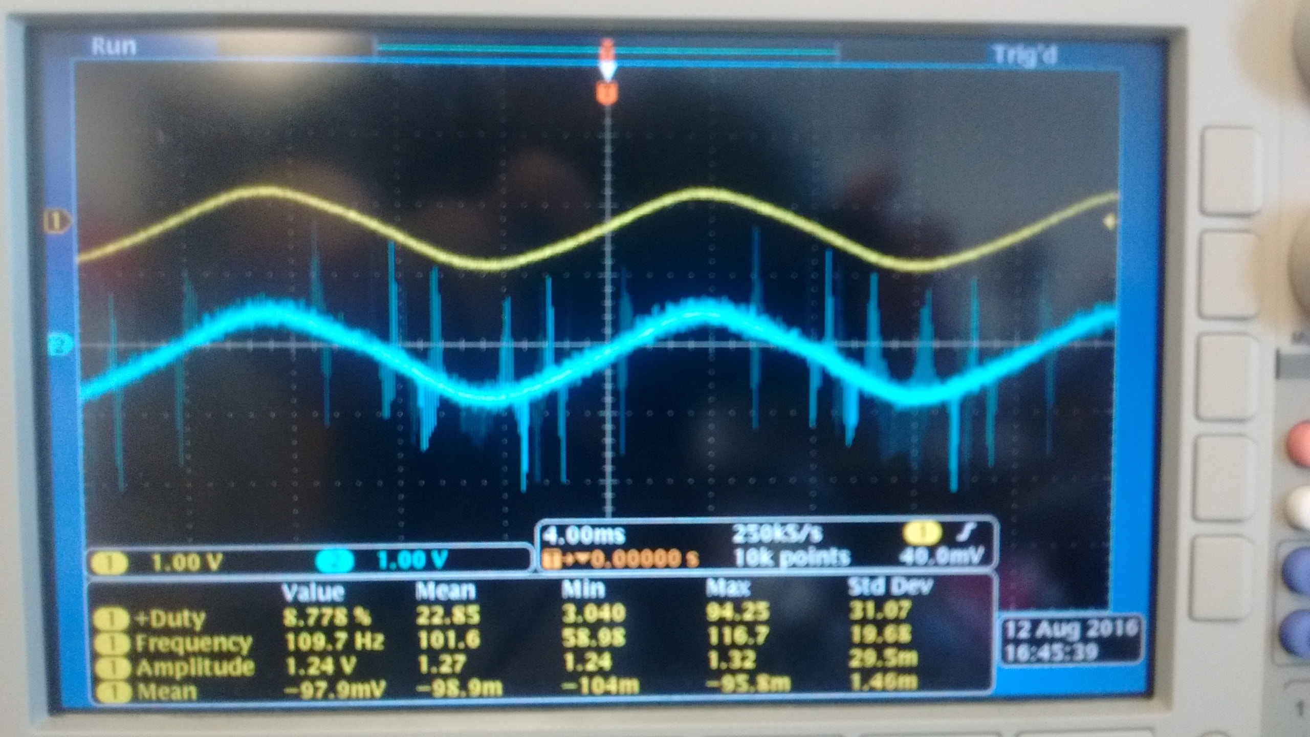
I currently use a NI 9215 module with BNC terminals to read the outputs of two different types of voltage sensors. Probe is a probe differential o-scope (Tektronix P5200A) which has a rejection of sound very good, while sensor B is a shunt isolated hall effect measurement using a LEM lv20-P and a custom PCB, which has a considerably lower noise rejection. Noise in the circuit to be measured is mainly the result of a H-bridge Inverter circuit that goes to 10 kHz. A picture of two sensors measuring the same signal displayed an o-scope is shown below with the sensor signal on top and B sensor on the bottom.
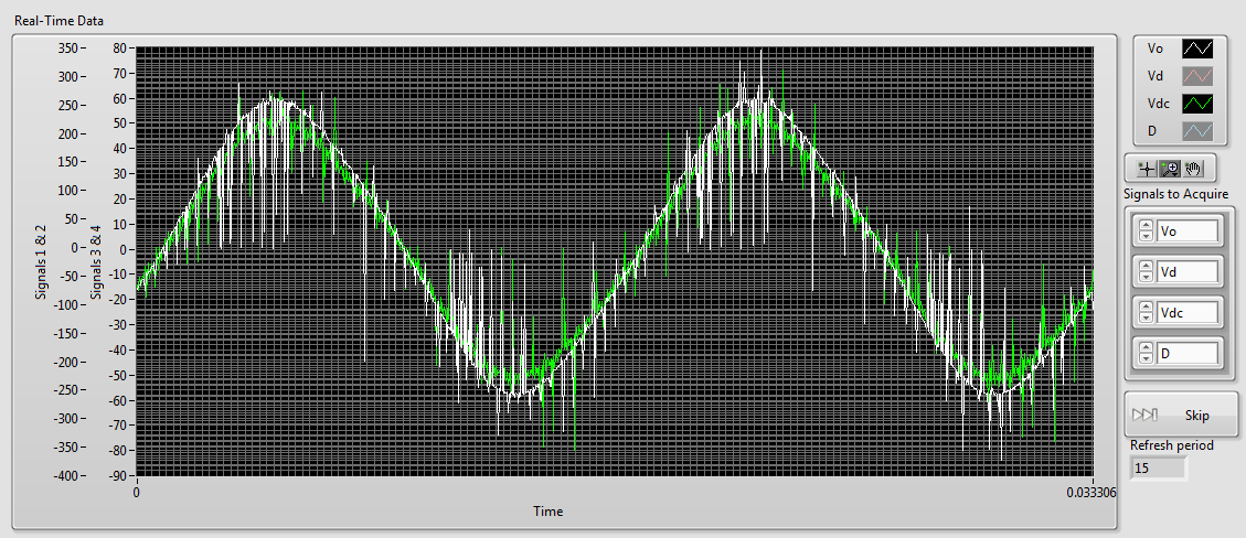
As you can see there is a lot of noise in the B sensor while sensor A is most often silent. When I connect then both of these signals to my NI 9215 I get the signals shown below (75 kHz sampling rate), sensor A appears in white and green B sensor (ignore the differences in scale, it's programmatically).
As you can see the noise level in the two now is comparably high. However if disconnect us the 9215 B, the signal from the probe sensor then replaces the image below:Although there are some present noise, the signal is much cleaner than before. The natural conclusion that I draw from this is that there is significant interference between the two signals. The same wiring is used for connecting to the 9215 as o-scope, and the two sensors use shielded twisted pair cables. This amount of crosstalk seems very high compared to the - 80dB listed in the specifications of the 9215. Any ideas what could be the cause, or how to fix it? Unfortunately, I am currently unable to afford a second sensor A.
1. by the impulses of the runt, I was meaning extremely short pulses on A sensor. If they are short enough, you will not see them unless you are looking for.
2. my concern is whether the switching noise is contaminant entering your power supply through the electric wiring. Of course, good feeds should filter this point, but it's just another thing to check.
3. the quick and dirty way would be to use a BNC T-connector to connect the oscilloscope and the ground in this way.
Suggestion of ferrite chokes on instrumentation Henrik is a good.
I understand that this type of inverter using the load (normally three-phase current motor alternative) to filter the frequency of bridge (10 kHz in your case) to the required frequency (normally 50 - 60 Hz). This means that high frequency currents go all the way to the motor, if they are not filtered by the cables first. You can not just screen the housing of the inverter, because the currents of high frequency down to load part of its operation. If you start testing things, you will all the way from the inverter to the load of the screen and will be impossible to Rodez to meet your instrumentation.
Standard WARNING: If you are tempted to connect directly to the UPS output and reduce until the input voltage range 9215: first of all, make sure that a qualified person has verified your wiring. Second place of fuses in all lines near where the tension is taken offshore. A UPS maybe a current loophole in the beach A 100 and you don't want that to the bottom of your wiring of instrumentation. Not directly relevant to your ad, but I feel that I specify.
-
The NI 9215 input signal voltage
Hi all
I tried to test NI 9215 BNC in MAX. And the acquisition of data took place without input signal.
The voltage for all 4 channels, I read is about 10.4 Volt.
Is this fair? I thought, the voltage should be 0 without input signal.
Best regards
GL
If you leave the open entry, it will tend to float to one of the rails. From my experience, it's almost always the top, so the 10.4 volts.
If you short-circuit the input, you'll get certainly 0 volt. You will probably get 0 or nearby yew, you put a resistance across the entrance.
-
Formula for conversion signal strain gage
Dear forum users and employees of OR,.
I'm fighting to check a formula used by DAQmx and LabVIEW for the conversion of a signal pledge of strain to the mechanical solicitations.
Formula for strain is "eps" (type of full-bridge III: 4 elements, 2 x 2 in the same sense sequence):SPE =-2 * Vr / (GF * [(nu + 1) - Vr * (nu - 1)])
See also '10. Full bridge III"here: http://www.ni.com/white-paper/4172/en/#toc10
But if I try to reproduce this formula based on figure 1-15 in the page web related, I can simply this:
VR = Vch/Vex = 1 / 4 * GF * (- nu * eps + eps - nu * eps + eps)
=> eps = 2 * Vr / (GF * [1 - nu])So either I make a mistake, either the formula given is faulty. The other formulas on the linked web page didn't quite work for me neither.
As reference, take a look at this: "full bridge, 2 grids of longitudinal-2 cross, second to the last entry on this page:The formula NOR mentioned can be found here as well:
NOR: LabVIEW 2013 help Convert gauges read VI
The formula I got for "eps" was posted by the employee OR in a different context (with a negative sign):
Can someone there explain further?
Good day!
Hi Wimba,
the formula that you describe is for folding (Type II) and not for the axial deformation of (Type III).
You must take into account that the voltage should be descriebed in the form of the restistors report.
See the Wheatstone bridge for that.
Hope that helped.
Anna
-
small pressure with NI 9215 readings
I use currently the cDAQ 9172 map with several modules of inputs/outputs, analog and digital data acquisition. I'm trying to use the 9215 analog input module to measure voltages by a single anemometer. The playback for the anemometer range is 0-1 V. However, for our use, we analyze the low speeds giving no more than 0.2 V.
When the anemometer is attached to the 9215 module it will not register any voltage read unless it has a very high speed (and thus a higher voltage reading). We tested the anemometer with a simple oscilloscope and it records easily tensions low low flow rates, so the problem is not with the anemometer himself.
So these are my questions:
Is it possible that the 9215 is not sensitive enough for the< 0.2="" v="">
There also the problem that the cDAQ-9172 also contains 6 other modules e/s and is housed in a Cabinet and the signal is lost in the noise/interference?
Can I try in LabView itself in order to increase the sensitivity?
A big thank you to all those who can get an idea.
Problem solved!
Apparently, he was the son after all. I don't know what was the problem, but it is fixed and all right.
Thanks to everyone for their suggestions and help!
-
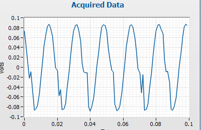
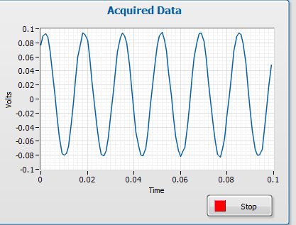
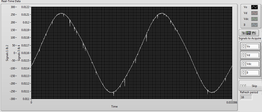
Measurement of deformation of the sine wave
Hi people.
I'm trying to measure the deformation of the signal coming from a range. Its a sine wave typical that distorts the increase of entry (see attachments). I was initially just to subtract a known since the signal signal to give the difference. The fault point by point is great for this. I also try to figure out the slope over time and rapid changes of the slope would indicate the point. However, point-by-point calculation of the slope gives too much error. Is it possible to generate accurate slopes or y at - it a function that determines if a signal is not sinusoidal?
Thank you
Select this option.
For a quick visual check, you can use vi tone detection and the export of the residual signal, maybe the effective value of the residues is a nice value (THDN)
Measures of deformation of a periodic signal (in general) often made in the frequency domain and called harmonic distortion. Also, there are screws that can already do it for you. (SINAD). The level of DHT is usually used. See signal processing - wfrm measure
Your traces resemble a calibration of accelerometer ball steel 1 g for me.

-
NEITHER 9215 delay in phase between two channels
Hello
I use Ni9215 with ENET-9163 to measure the phase between two sinusoidal incremental signals delay. First signal connected to AI0 and, secondly, to AI4 at 100 k sample rate. I know 9215 simultaneous ADC, but it seems to me that NI 9215 gives additional time between the channels. Is it possible, or l mistaken?Alexandr.
Hi Alexander,.
Please let us know how you get on,
Chris is correct - with the idea of using a right signal to both channels, I tried to suggest this earlier...
I hope this helps with your problems with delays,
-
Analysis of the order when there is a significant shift of DC signal
Thanks for reading this. I use the Toolkit NI LabVIEW Order Analysis for direct analysis of signals of pledge of deformation of an attachment to a car engine. My goal is to acquire data of a part of the calibrated strain connected to an engine during the rampup and identify the controls in the signal of the strain. I am not able to understand a problem I see with my results in the power of order spectrum.
I measure the signals of pledge of strain during the preparations for engine using the module 9235 cDAQ (1000 to 6000 RPM in 15 seconds). I also acquire the tachometer using the module NOR-9402 (counter). Then I converted the signals of the strain at the same angle signals and made the order power spectrum.
Please order power spectrum resulting Fig1 shows. What I find that is the DC offset in the signal of strain presents itself as a high amplitude (red or green) peaks in the power spectrum of order (see Fig 1) around the order of 0. Because of these enormous peaks around order 0, the peaks of the order of a real interest around 2 or 3 command (blue or purple) are difficult to discern in the graph.
The DC offset clearly shows the chart of strain vs RPM (RPM is a linear function of time), if necessary, it is identical to the strain vs time. The white line in figure 2 corresponds to the DC offset. In this example, the CC offset is constant during the rampup rpm, but more often, the party calibrated strain of experiences both change static and forced lengthening cyclic as in Fig. 3. Here the sudden part increases the deformation in traction, with cyclic constraint superimposed on top of that.
My questions are:
Am I missing a key here in preprocessing step?
-I need a high pass filter to remove DC offset?
Subtract the average value of the signal from the time signal based before sending to the treatment?
How does a handle signals that have a variable static elongation a cyclical signal above the static signal? This appears to me a common scenario in the measures of constraint because ESA undergoes two different static and dynamic constraints in a motor boat.
Thanks for your comments and advice!
You have several choices, depending on what you want to do.
If what you want is a nice parcel of land, and the DC signal not enough to affect your 1st order, then simply set the component continues to 0 once you analyze varies.
Presto - instant removal of DC. It is perfectly legitimate, as long as the domain controller is not wandering too. Mathematically, it is exactly the same as the withdrawal DC before analyzing. (an inverse THAT FFT of this result and you will get the signal without DC, if you don't believe me).
OR
You can do as Bob has suggested and take the average. If your length of block is short compared with the rate of change of the real continuous component, it is fine.
OR
You can remove the trend by interpolation. For example, for a block of 1024-pt, find the way to 100 points around (on each side of) the beginning of your block. Find the way to 100 points around (on each side of) the end of your block. Find an equation (Y = mX + B) to describe the trendline it and use this equation to subtract a different DC value for each point.
OR
You can remove the trend extrapolation and interpolation. For example, for a residence of 1024 pt. find the average of the first 100 points and the last 100 points and assign these values X = 50 and X = 973 (1023-50). Find an equation (Y = mX + B) to describe the trendline it and use this equation to subtract a different DC value for each point. You need to face the fact that X = 0 starts BEFORE your trend line at X = 50, but that is basic algebra.
Remove trendline technique is more accurate and necessary if the domain controller changes siugnificantly during your block.
-
Multifrequency 9223 9215 sync and 9213 in cdaq 9188
Hello
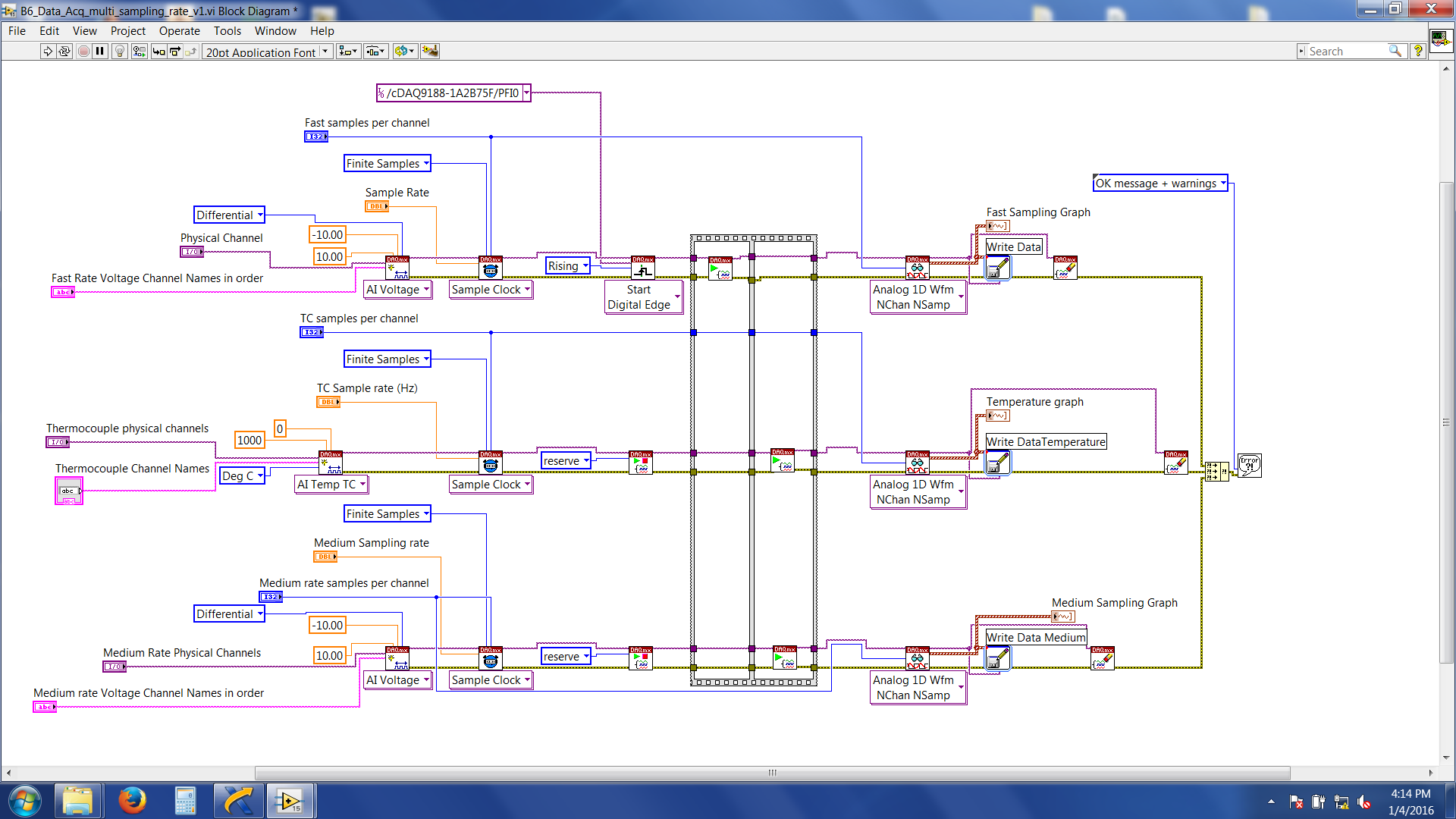
I'm trying to synchronize three different modules (NI 9223 and NI 9215 NI9213) every acquisition given to various higher sampling frequencies (e.g. 9223 = 1000 hz, 9215 = 100 Hz and 9215 = 2 hz) and write files to separate data for my task. I am using a cDAQ-9188 ethernet and all modules are in the same chassis. There is an external trigger (which comes from an external source) to start acquiring data which are wired connected to the PFI0 channel in the chassis. What I want to do is: whenever the trigger is high, acquire 10seconds of data according to different sampling frequencies high above and write in separate data files. I followed the procedure referred to in the http://www.ni.com/tutorial/5376/en/
Here's a snapshot of the block diagram
Now, the problem I am facing is the 'average frequency (NI 9215) data' and 'data of Thermocouple (NI 9213)' are acquired and written immediately after that I have start the labview program. Fast speed data (NI 9223) are not written, and wait for the trigger signal. And then it throws an error 200284. If I do just a finished sample rate on NI 9223 alone (without adding/attempt at sync with other modules) with expectation of release it works without any problem.
LabVIEW files are attached.
Suggestions very much appreciated and you wish all happy new year.
Thank you
Roy
Hi Roy,
'average frequency data (NI 9215)' and '(NI 9213) Thermocouple data' is acquired and written immediately after that I have start the labview program.
Yes.
You forgot to set a trigger to start these DAQmx tasks!
And then it throws an error 200284.
The description of the error says something like "use a higher timeout value. Have you tried that?
-
Syncronize to acquisition of data with the generation of signals
Hello everyone,
My request is generate pulses on the output of two different to drive two LEDs and acquire detected pulse signal amplified photodiode.
Actually pulses are generated by starting the writing on the analog output, and then start the acquisition (I need 200ms on average), stop the acquisition, turn off the driving LED and develop the acquisition and record the results.
All this in a cycle it takes about 1.5 seconds to run.
Next step would be to drive the outputs with a waveform (duty cycle of 50% of width of 250 ms) and acquire the signal of the photodiode in synchronization with the edge of the pulse.
I tried to use the trigger function, but the examples are not clear on how to do it.
I use NI 9205 or 9215 to acquire signals.
Is there a particular entry to be used as a trigger?
Thank you very much for your attention
Hello
I found that NI 9205 has inputto that one be used as trigger signal, i.e. AI0.
At latest
Eugenio
-
Hello
I am a new mechanical engineer on FPGA and LabVIEW Real-time. I was trying to connect a sensor accelerometer for the NI 9215 Module of the 'C' series in the controller chassis 9024 cRIO but lives a hard time to find the right connections, especially with the 'GROUND '. I would appreciate a lot any effort giving me more insight on the problem that I am known and help me acquire a voltage signal. I went through various white papers, but none of them explained in detail.
Hi KarthikSrinva,
What you have described might work, but don't forget that the 9215 has a maximum range of +/-10V of its own reference to the ground (COM).
Because the battery is a floating (unreferenced) voltage source, you'll want to fill them HAVE - COM (common ground) terminals and to ensure that you have a common reference and the differential signal is not float out of reach of data acquisition. What is described in Chapter 3 of the guide to wiring field and noise considerations I think you were talking about earlier:
Wiring and considerations of noise for analog signals
http://www.NI.com/white-paper/3344/en/#toc3
Kind regards
-
I am a new user and am confused by the signal provided by devices simulated in MAX and can't find an answer anywhere. I'm using Labview 8.2, MAX 4.2, DAQmx 8.5, cDAQ-9172 and the DAQ Assistant, simulating a 9215 card. I understand that the simulation is a noisy sinusoid, but what is the frequency of this wave? It seems that you can change with sync settings in the Configuration Wizard panel.
It seems to me that sync settings would deal with the samples the 9215 incoming signal, right? On the contrary, it seems that these timing parameters change the frequency of the signal itself. For example, in the DAQ assistant, if I run a test field absorbing N samples and read samples of 1000 to 1 k Hz, I see a cycle of a noisy sinusoid which takes 1 sec. If I read 100 samples at 1 k Hz, I see a noisy a sine wave cycle (with less resolution) which takes 100 ms. This does not mean that my frequency signal has multiplied by 10? I expected to see only a part of a sine wave had the original frequency remained the same.
Also, when I run using acquisition mode continuous sample it seems that the time required to go from Ridge to Ridge is different once again. Here, he does not appear to make a difference in what is the sample size, but rather what is the sampling frequency. 1 k Hz, it takes about 10 seconds and 2 k Hz, it takes about 5 seconds.
Please be aware that as a newbie, I'm not far enough along to fully dissect the DAQ assistant VI to see what is happening, but who will be the next. So, I would appreciate any simple explanations as to why I see what I am.
Hi pfrank.
It is not documented, but the simulated sine wave (measured in samples) period appears to equal the size of memory enter task buffer, at least for the tasks of buffering. The size of the input buffer is based on various factors (finished/continuous samples, by channel, sampling frequency). These are explained in the NOR-DAQmx help file that is installed in the Start Menu under National's Instruments\NI-DAQ. Search for "How is the buffer size determined? (without the question mark)
The selection of N samples leads to the DAQ Assistant set the mode of the sample to over, so the size of the buffer is exactly equal to the samples per channel. If you select continuous samples instead, the size of the buffer will have the value 10 kS because the sampling frequency is between 100 s/s and 10 kech. / s and period of the sine wave will be 10000 samples. If this doesn't make sense, look at '' How is determined to buffer size? '' in the NOR-DAQmx help.
DAQmx does not support the provision of your own simulated devices simulated data. If you want to control the simulated signals, you need to add code to your application that replaces the data returned by DAQmx.
Brad
-
CDAQ 9191 or NI 9215 there a fpga module that we can program?
Is it possible to perform mathematical operations with the signals that we gain by using cdaq 9191 and NI 9215?
Once the 9191 is set up in MAX, you can read the channels on the 9215 and do what you want with the data. The 9191 is used only to transmit data from the 9215 on a computer that is running LabVIEW, where you can perform mathematical operations.
If you want or need FPGA, you get a compact chassis of RIO, not a compactDAQ chassis.
Maybe you are looking for
-
4MOT/4 Error Code / 40000003:HDD - 1229
I ran AHT and has got a unique error code- 4MOT/4 / 40000003:HDD - 1229 Disk utility does not show a problem. It is a mid 2010 27 "iMac. Do I need to have the hard drive replaced?
-
Hello I have a Macbook Pro with a WD passport for mac that I keep all my photos on. I know that time machine will back up there if I plug it into the mac and select it to be excluded from the United Nations through the time machine preferences, whic
-
I have a pavilion g7 - 1113cl notebook and need a way to be notified of the drivers and BIOS updates and other. the only problem may be, it came with win7 64 bit installed and the fool who has recently done a reinstall 32 bit win7 installed...
-
nVidia graphics card GeForce Go 7300 on laptop Lenovo 3000 N100 0768-family failure
I took my Lenovo 3000 N100 0768 - family portable computer to a computer laptop shop the other day because I couldn't get anything to appear on the screen to power on and the report I got back from telling them that the motherboard needed a "BGA rewo
-
Message error 0x80194F7 & 0 x 80004005
Since 5 February my Live account email shows the 0x80194F7 error message. When I ask to update all the emails it starts to download the emails I sent previously for some reason any. Then it says cannot send or received e-mails in the Live account an