Desired freq / real freq
Hi all
I'm converting a program of LabWindows/CVI to use traditional NIDAQ to NIDAQmx. Something I don't see in the API NIDAQmx is the distinction between the desired frequencies and actual frequencies for example what a signal or acquisition of a generation. Is that mean that the material can guarantee any frequency within its range (internal divisor not more mutipliers to a basic freq)?
Example with NIDAQ:
DAQ_Set_Clock (Dev, 0, DesiredRate, 0, &ActualRate);
WFM_Set_Clock (Dev, 1, 0, DesiredRate, 0, &ActualRate);
I suggest you call DAQmxCfgSampClkTiming to set up the sample clock.
To reread the sampling under duress, I would use DAQmxGetSampClkRate after that sync has been set up.
Best regards
Tags: NI Hardware
Similar Questions
-
PAL HD to SD anamorphic for UK broadcast
I have to back my first TV commercial for UK release (summer deliver to the United States for decades).
All sheets (7) say that they will only accept PAL standard def "full height anamorphic" (16:9FHA)
I drop my 1920 x 1080 @ file 25 fps in PAL DV widescreen sequence and I see narrow black bars on the sides.
Then, I do the math, height: 576 / 1080 = 53.33%, width: 720 x 1.4587 (BY) / 1920 = 54.7%
Looks like this works well.
Seriously... I have to do the MATH to create a common (in the United Kingdom) format file?
Then on top of that, they want the dominant upper field, and first was WITHOUT preposition for field superior PAL (SD)!
How guys across the pond do you? Any recommendations?
Oh and while we're on the subject, the specification sheets do not appear to say anything about the actual audio levels, they only spec:
Noise levels: the EBU R128 and sound intensity: ITU - R BS.1770
Search Google suggests this are measuring methods, but didn't indicate a desired level (real number).
So I found a document (in my search on the internet) that said more than desired level related pourrait be LUFS-23
Someone saw UK it?
I thank you very much.
I would like to change in a native HD sequence and use an export that is similar to the following: use ' scale to lose the black bars and check the MRQ in order to improve the HD to SD conversion.

The Audio level of the majority of British broadcasters is indeed - 23db LUFS, use the audio effect of loudness CC radar to measure this. Tones line up and the bars, I expect, will have to be added to their specifications.
-
Synchronize the ctr1 at ctr0 (generate outputs freq) via the signal of export
I need help to configure the output channels of meter on my card pxi-6723. Here's what I'm trying to do:
-have the possibility to synchronize the ctr1 exit toward ctr0. Note: ctr1 must begin on edge increase or decrease output ctr0.
-be able to change idle, freq. etc for each of these outputs
A sample that I worked on is attached. It works except the ctr1 output is trolling by cycles of 1 to 1.5 (according to a State of rest, edge selections). This delay is due to me having to put the slave (ctr1) task run after the masters. Note: The reason for this was the task of enforcement of crt0 (master) was the origin of the false triggers when exporting the trigger signal.
Its there a way of software trigger ctr0 OR delay its release until both (ctr0 & ctr1) 'perform tasks"have been launched?
Hi groz,.
I have not tried, but I expect the following sequence to prevent false triggers:
DAQmx control Task (ctr0 task, Commit)
DAQmx Start (task ctr1)
DAQmx Start (ctr0 task)
Principal ctr0 has it on its state of rest.
Also, I think you can do this trip without using a PXI_Trig line. To Start.DigEdge.Src the ctr1 task, specify "Ctr0InternalOutput". (To make the Terminal Ctr0InternalOutput appear in a Terminal of DAQmx e/s constant, right click on the constant, select "I/o name of filtering...) ("and put a check mark next to"Include the advanced terminals").
Brad
-
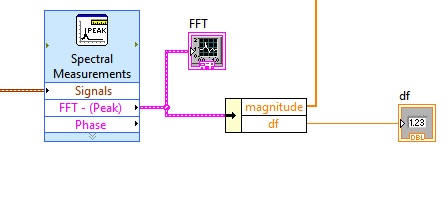
I am trying to extract the data of frequency of my FFT as I pull data from the scale, as a 1 d array, in order to write easily in an excel file.
As shown, I can get the delta-freq value, and I could do a loop for which calculates the values with the value of dF, but I would very much rather just extract the entire table that I do with "grandeur." Y at - it an option for this, or should I write the loop and calculate values?
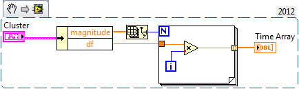
Build yourself a table of frequencies, like this:
(Just realized the label of the indicator is time table - as I usually do this waveforms.)
You can also pass the array of magnitude in the loop with an autoindexing of entry, while omitting the size of array primitive wired for the number of iterations.
Edit - to answer your question, no, there's no other easy method I know.
-
I need to know the Freq of my HP Pavilion wireless adapter is 2.4 or 5 ghz?
The specifications for the HPE 440f does not say, it lists only the 1 GB under network but mine as also wireless adapter card and says nothing wireless.
The number of prod is: BM 427AA #ABA.
It runs at 2.4 or 5 ghz? OR is it the PC Wireless not cela and decides to only commicates the router and the router?
Anyone know?
Hello
Not too bad at all, a large number of machines still use 2.4 GHz. In my house, all printers (HP, Canon, Epson) use of 2.4 GHz. Any computer that uses b/g/n uses 2.4 GHz and my observations, ILS ALL FUNCTION properly. The card will probably remain for the life of the machine.
Kind regards.
-
Motorcycle G 2nd Gen global and French freq.
I plan to use a soon-to-be purchased Moto G 2nd gen Global and leave me puzzled the frequency and speed of the network are compatible (I watch but my sources seem to be mixed).
My main goal is he reliable use 3G and may choose to wait for a 4G Unit...
-
Wrong time file Express with NI9361 medium Freq dynamics of the signal
I have an interesting problem with recoding of the frequency to a file with SignalExpress measures and a NI9361. I was able to find a workaround, but here's the question:
As in the attached SignalExpress project, I'm analog acquisition of voltage using a NI9234. In this case, the module is in place only for the/cDAQsim/I/SampleClock channel exist for my next step to reference. I'm also acquisition of previous frequency with the NI9361 in dynamic mode with an average using the reference to external clock of the analog input stage. Then I have a backup at the ASCII stage where I want to write a file leave ASCII, comma with absolute time.
That's the problem. In this case, I cared only to save the frequency to the file. But, when I did the absolute time would count per second for 100 points, then loop back at once and County place again. (See attached Test01.csv.) This is the same behavior that if I tried to record data using just the NI9361 without an external sample clock.
If instead, the save operation I take FIRST entry then the frequency I will get a file with the correct absolute time as Test02.csv analog, attached. Even if I save the frequency as the first entry and then return to tension the problem at the time scale.
Anyone know why that would happen? Is there a simpler way for the frequency measures stamped recored with the NI9361 and SignalExpress without analog data recording? without using an analog input module at all?
Hello
This question looks better suited for the Signal Express community forum page. Please ask your question here.
Thank you
-
DMM (NI 4070), how to correctly set AC Freq (bandwidth) by the sampling rate
using a NI4070 multimeter and I see the max connection is 300 kHz by respect it. But I don't understand how to set the min and max, acFrequency according to the sampling frequency or speed reading.
6 1/2 digits resolution, the speed can vary from 0.25 s/s to 100 s/s and this range corresponds to a lower end on the connection (minimum acFreq) from 1 Hz to 400 Hz.
(Q1a) - is the playback speed, controlled by the minimum setting of IviDmm_ConfigureACBandwidth? or vice versa?
Otherwise, I do not see how to control the rate of reading or the sampling frequency. IviDmm_ConfigureMeasurement only allows you to control the range and resolution.
(Q1b) - is there a way to directly control the sample rate (digitizer) or playback speed (dmm)?
(T2) - the upper limit of the bandwidth of AC always seems to be at 300 kHz... is there still a reason to reduce this maximum value?
(T3) - Finally, unlike the traditional niDmm function, the resolution via the IVI configuration should be passed as absolute value; does directly when number of digits and the beach? For example if I want to 6 1/2 digit to 300V range, I guess that by the specifications that the resolution should be set at 0.001 V... followign, if I want 5 1/2 digits to 1V range, the resolution should be set to 0.00001 V?
Hi Rjohnson,
I'll try to answer your questions as best as I can:
Q1A. The ConfigurACBandwidth function is used by the driver OR DMM to calculate the good aperautre for the measure. So yes, by adjusting your minimum frequency, you will affect your reading speed.
Q1B. Your reading rate will depend largely on your measuring cycle. To get a fast measuring cycle, there are a few things that you can adjust. You can programmatically control your time aperature, as well as your time to settle.
Q2. I can't find a reason to change. This parameter is only used for error-checking and verifies that the value of
This setting is less than the maximum frequency of the device.Q2B. I think what you say is right, but I'll need to check on that - I'll let know you as soon as.
Hope that helps. "" "I would recommend checking the explanation of the Cycle of the DMM measurement in DMM help' devices ' NI 4070" DMM Measuments "DMM measurement Cycle.
Take care!!
-
sr830 connected with rs232, read freq and tension doesnot happen simultaneously
Hello
I'm having a problem, try to set the frequency and voltage in the auxiliary output simultaneously. I wrote two codes, one to determine the frequency and another to set the voltage of the auxiliary output and used them as void / screws in my main program that, at the moment, contains only these two elements. When I run the program the first time, the two frequencies and voltages are defined, but during subsequent runs that one has the value whilw the other keeps the old value and I have to run the program again to set this parameter. What is the problem? can u please help me. I'm just a week in the labview programming, but I have to implement hysterysis C - V in time very short, which these controls are a part. Please find attached programs.
The next problem is your termination characters. Your string constants indicate a \r\n, but the problem is that they are in normal mode and so please send 4 bytes of a backslash backslash, r, n. You must edit these constants to be in mode '\mode' of the backslash so that when you enter \r\n, it is in fact two bytes, consisting of a carriage return (ASCII 13) and line feed (ASCII 10)
-
FFT vi truncate the FREQ of signal.
Hello
I noticed that the FFT vi truncate my signal. See attachments.
I'm basically the noise of a signal (I have both the phase - I - and out of phase - Q-signals...)
(Ignore the vi curve, it is just to remove the continuous component of the signal, it's irrelevant to this discussion).
Kind regards
Ali
You lose your calendar information for data going to the graph of the PSD. It works on arrays. The FFT functions assume a dT or dF 1. So when things are placed in the chart, you will see values up to 0.5 since Nyquist limits you to 1/2 of the sampling frequency. PSD2 graph doesn't have this problem because the blue wire of the DDT keeps the calendar data.
If you build your table in a type of waveform data and the boot in the value of dT, your data should look like the other graph.
-
Entered FREQ XControl, first attempt XControl
My first attempt an XControl is attached. I'm looking for comments on the things I have forgotten and areas where the code could be improved. I am also not entirely satisfied with the appearance of the control, so any suggestions in this area would be good. The version is 8.2.
Hi gchristi1,
It seems pretty good so far! The only great thing that I saw was the code outside the structure of the event that defines some values and appearances. I'll try to put this in some cases, the structure of the event, or in a case outside the structure of the event. In this way, that you do not call this several times unnecessarily.
-
Problems of acquisition & visualization: fails at 100 Hz, OK more low or more freqs
Hi all
I have some data acquisition & visualitzating problems.
The acquired data is a voltage (0 - 10V) from RDP LVDT & conditioner. My pourpose is simple: I want to gain everything by visualizing and recording to disk. I use a card BNC-2101 & 6062E. I also use LabView 8.5 on Windows XP s.p.3. I tried three ways: my own .vi and examples of LabView with internal clock and the external clock. They all consist of two steps: aquire, visualize data on a graph. and my own .vi also saves the data in a .lvm.
On the first try, I was able to acquire data with sample on request mode. But I want to get to a known frequency, so I put 1-sample (controlled HW). I set the frequency and the number of samples as well as the number of samples is of approximately 1/5 of the frequency, for a rate of graphics path 5 times / sec., BUT I found the following problems:
(1) for the acquisition in the low frequencies, say 50 Hz, there is a large gap between read data a shown in the data graphic: from 2 to 8 seconds.
(2) for the acquisition to high and very high frequencies, say 20 kHz to 100 kHz, the graphic works OK. But in this way, the file I'm writing is too much. I don't understand why when I put the computer work harder, with more data, it appears without delay.
(3) for the acquisition to 100 Hz, it does not work. An error (just know don't remember the #, is one who says this time-out has been reached whithout having given to read aviable). 99.9 Hz works, but not at 100 Hz or 200 Hz. I really don't understand this point.
Can someone help me please?
Thank you for your attention,
usuario
Just writing to tell you that we have tried with another computer and had no problems with the hardware and the same .vi.
And have had no problem for the las 2 months.
Thank you all for your dedication.
-
Samples and sample FREQ. / Chan
Use of LV7.1 with Win_XP.
In a DAS code, using digital dashboard counter to pull a loop timed. (See attached diagram)
Initially I was acquiring only one channel and required a loop timed with a timing of 50ms. So to set the sampling at 200 Hz frequency (period of 5 ms) and took 10 samples / Chan. So I got exactly 5ms x 10 = 50ms.
Later, I gained 5 channels @ the same 200 Hz and 10 samples / c. To my surprise, I got the same timed loop triggers 50ms. I don't think I'm clear whats happening? The number of channels that I receive does not seem to change the triggers of 50ms.
Thanks for any clarification on above.
Has released this disk VI (should have gotten the forums earlier) and who had an answer for all my doubts!
-
Hi all
Having x 201 Tablet with 3Gigs and want to do an upgrade. Check memory size max for my 8 GB model but what should the frequency be?
Have a 3093AA8 motherboard and a QM57 chipset.
Thanks in advance! You will enjoy if recommend you a brand? Kingston/Corsair/Samsung...
KR,
Ognyan
1333 mhz SODIMM DDR3 is what the X201t use (although 1066 mhz also works). Corsair, avoid any brand should be correct.
http://www.Flickr.com/photos/lead_org/9058136495/<--- this="" is="" my="" x201t="" with="" 1333="" mhz="" ram="" running="" at="" its="" native="">
-
Frequency rate real pulse readings
When I set up a counter to generate pulse train using 'DAQmx Create Channel (CO Pulse Freq)' and provide an arbitrary value at the entrance of the "frequency", I can read the value of the real rate?
SampClk.Rate on node DAQmx Timing property returns zero.
Too bad, it turns out that the FREQ counter. appears in the DAQmx Channel node. Go figure.

Maybe you are looking for
-
Hello I use a Toshiba laptop (model: Satellite L750D psk4ye).I use Windows 8 pro (32 bit). for a few days, I saw a massage in my hard drive alert-* "Could not get the information from the disk, cannot use the alert function". *How can I slove it? Wha
-
Dolby Digital, bluetooth, screen brightness, and win7, Y550
for as far as I know the drivers on the website of lenovo for win7 x 64 everything works except the ability to change the brightness of the screen, the button digital dolby, will get and I don't even know if its actually a function, but the ability t
-
Server 2003 SQL Express 2005 Service Pack 4 update fails with error0x65B
Repeatedly fails in Windows Update
-
That's the problem In the title
-
(Redirected) Help: R630 preferred transmission and PCIe Flash models?
Hello I bought a R630 MOU with two processors and 64 GB of RAM and two basic disks. I need about 4 GB of storage. My provider suggest me use 5-6 pcs Dell 1 TB 7200 RPM SAS - 2 readers, do you agree or do you have other suggestions? The R630 is supp