Digital modulation
How to multiply random digital waveform model with waveform sine in order to get ask modulation scheme
wire-LEEP
You can watch these:
You can also convert from DDT and then multiply directly with the multiplication VI using the same number of samples. Remember also that the multiplication of waveform must have the same ' dt? This means that, with different frequency and simulated signals will not work. I hope that this gets you going
Tags: NI Software
Similar Questions
-
Hello
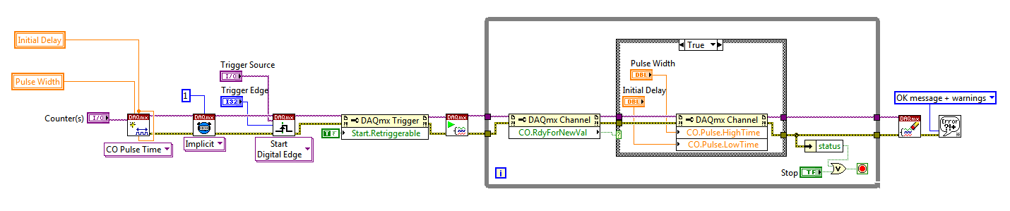
I use a mx-acquisition of data (NI USB-6211) and I would like to use it to generate a pulse of digital modulation
that is triggered by an analog input signal. The input signal is a pulse of squares analog modulated
What is almost periodic. It's because of my set up, and I can't do anything with it. I would use the
before the edge of this signal to trigger the production of a digital pulse signal modulated (0-5 V). My
problem is summarized in the figure given in the annex. I would also like to have the possibility of
Configure the 'backwardness' and the term of "TAU_LED", while the VI works.
I have looked at several examples of instrument OR meter generation, generation of PCI I / AO, but doesn't
not managed to solve my problem. Does anyone have an idea of how start with my problem? Are there
No matter what example VI that I could start to change?
Thanks in advance,
Gregory
Hi Gregory,
Sorry I forgot to mention: the Initial delay applies only to the first impulse of a redeclenchables generation. Every subsequent impulse will use low time as the Initial delay. I agree the behavior is not very intuitive (our latest guidance of series X actually supported an Initial period to allow on property Retrigger), but it is described in this knowledge baseand should also be mentioned in the DAQmx help.
As you generate just a single pulse, I would recommend simply connecting the Initial delay and at the entrances of low time to the same value for each pulse will be delayed further.
Exit tasks ongoing counter currently supports DAQmx writing. However, the finished generations or simple impulse are not. However, you should always be able to get the behavior you need with a property node DAQmx. The current solution on the series E/M is:
Again, this is not the most intuitive, but I checked that it works on my 6210. After writing a new value in the software the pulse will be updated on the 2nd trigger. Attached is the code stored in LV8.2.
Best regards
-
24 v digital signal of the event from the host to the fpga power on/off
Hello forums or
Sheet material
cRIO-9074
module or 9472 digital module 24 V output c series
To expand on the topic described,
I want to be able send a trigger to alarm the fpga digital 9472 out that lasts 30 seconds using the operating system time real clock time on the host computer
The way I approached this problem is that
In the loop where the event occurs, if the event trigger is defined then the fgv has a time stamp when the event occurred is sent.
In the loop that communicates with the control of fpga, I write to the control based on the condition that the difference of the current time checked and fgv time is 30 seconds or less, then it will send the value true, otherwise send fake and wait for the next occurrence of the event.
The main problem after implementation of this is that 9472 led does not turn off when the false value is sent to it.
cordially Mzamanstl
Timer Keeper SD is a FGV so that it is written for her, once the event occurs
So if the event occurs so timestamp is stored and then the difference of the timestamp result is<30>
then a true value will be sent to the module of 9472
So basically I want the light and I want to do the 24 v output for 30 seconds then turn off and wait for the next occurrence
I think the method that I test it with is not very good, because I realize other factors that may contribute to this problem, so I think I found another way to test
and I will try it but its will take time.
cordially Mzamanstl
-
LabVIEW interface with multiple blocks of Festo module
I am trying to connect with a block of Festo, but I can't. Here are the details:
I'm under Labview 2012 SP1 with IndComm-DeviceNet 2.2 pilot on a 64-bit Windows OS. I installed a PCI 8532 card NOR. I see the map to the MAX.
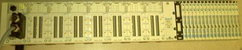
The block of Festo is built with the following Modules: CPX_FB11 (communications module), 4 analog input Modules, 1 Digital module, 2 digital modules followed by 32 Festo valves. (Image below)
Using DeviceNet PXIPCI Basics.lvproj I did the following:
In the project, right-click on desktop > New > targets and devices > existing target or device, discover an existing target or device...
Expand the node of DeviceNet Master Interface, DeviceNet1 chosen and added to the project.
A click on the newly added DeviceNet/device target > New > targets and devices...
Expanded the Festo Block "CPX_FB11" selected DeviceNet slave device and added to the project.
Initially, I received an error card technique 'EDS file no assigned' I solved this by following the direction listed here.
However, I'm unable to "see" anything other than the CPX_FB11 LabView. The tree view of the devices lists not analog, Digital e / s or valves. I can't operate the Valves and IOs digital or analog. When I run the entire project VI they then expire.
Any help would be appreciated.
Thank you
Tennessee Paul
Hi Jesse,.
I'm not entirely sure what the specific problem was. I kept getting strange behavior. Errors in LabView and on my camera from Festo. The EDS files change. So, I did as any natural born THERE would be worker, I rebooted.
Here are the steps I used to get this project going. In doing so, I found that to set up a DeviceNet device in LV2012SP1, no need to manually enter the data in file EDS. There is a tool to load files EDS. It dealt with issues I had in the previous Forum posts: here about loading files EDS in LabView and here regarding setting up a DeviceNet network.
Environment: Windows 7, 64-bit processor. IndComm 2.2 pilot. LabVIEW 2012 SP1
Starting with the example LabView project: "Devicenet PXIPCI Basic.lvproj.
Add a DeviceNet master to a LabView project
- The project: right-click on my computer
- Select new
- Select the targets and the device (s)
- Select the option "discover existing devices.
- Select the discovered device.
- Click 'OK' (Note: in this case, my master is a card PCI of NOR-8532)
Add a DeviceNet slave device to a LabView project
- Right-click on the master device newly added in the project tree
- Select new
- Select the targets and the device (s)
- Select 'discover existing devices.
- Select the discovered device.
- Click OK. (Note: in this case my slave is a block of Festo CPX-FB11.)
Load an EDS file to the slave device
- Right-click on the slave device
- Select "Sheet"... »
- Click on add files...
- Navigate to the location of the EDS file.
- Select the file.
- Click OK.
- In the left pane, expand the data sheet newly added up to reach the node displays the version.
- Select the version.
- Click OK.
Check the device and file EDS
- Right-click on the slave device
- Select utilities
- Select the Panel of Test online
- Select the option 'Device status' in the field of category on the left.
- On the right, select the slave device, you want to check.
- Click on "check the device".
- Read the errors/warnings or lack thereof.
- Navigate to the following location: C:\ProgramData\National Instruments\NI-IndComm for DeviceNet\Datasheet
- Remove the sheet (Note: there is more that one datasheet added manually.) Additional EDS files come with the IndComm driver. Find the EDS file for the specific device that you want to replace and delete).
-
Pulse modulated CW with the PXI-5650 and PXI-6653
Hello
I'm trying to generate a signal CW of pulse modulated with the PXI-5650 as source RF and the PXI-6653 as the modulation signal. Basically, I'm trying to generate a simple radar waveform. It seems that it would be possible to use the synchronization Module (6653) to transform the RF output on / off on the signal generator (5650), but I do not know how to route the signals from one to another using LabView.
Has anyone tried this or something like this before? Can anyone please offer some advice?
Thank you!
-John
Hi John,.
Reading your post, it seems you want to use your calendar and map of synchronization to the RF output power, in other words, on Off Keying. OOK modulation is a feature built into the 5650. For more information, you can navigate through the NI RF Signal generators Help for devices-RF signal generators > NOR -> NOR 5650/5651/5652 overview-> Modes of Modulation and simply click on the Modulation Modes.
An example of this is found in the example Finder OR by navigating to the help-> find the examples in LabVIEW and then navigate in the Finder to example NOR material input and output-> Modular Instruments-> NI - RFSG-> signals-> RFSG 565 x Digital Modulation.vi.
Kind regards
Jason L.
-
How to generate 3 Wick using digital signals
Hello
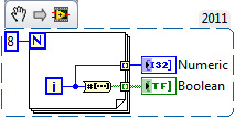
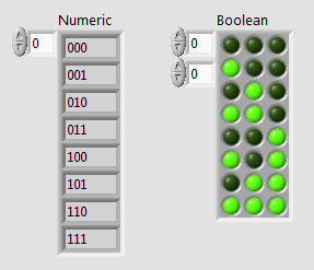
I am in the course of generations bit 3 digital using 9403 digital module and cRIO 9014.I signal must generate all combinations from 000 to 111.la so I have to give the Boolean constant either true or false 9403.I output module'm not gettimg how incrase step value of 000 001 and so on... Should I use the shift register?
I know how to use the registry to offset for integer value bt I don't hv any idea on the Boolean value.
in the hope of solution...
Here is a small example that uses the number to array of Boolean function. The digital indicator has its display of the binary value (%b) formatting.
-
How to initialize a session of calibration of the NI9215 module
Hi all I'm trying to make adjustments to one similar to the Digital module (NI9215), I found the calibration is out of specification. I downloaded the calibration for the NI 9215 on NOR-Daqmx platform procedure and followed the instructions. The problem arises when I reached the part about how to adjust the calibration values, it is said to initialize a session of calibration but does not specify how you're supposed to achieve this goal. I use the max Measurment 14 version and I got development after 2013. Any help would be appreciated.
Hey smudger.
I looked on your problem and I think I found the vi you are looking for. I am attaching a file containing what I think that you need, but you can also use Quick Drop (ctrl + space), and then search for DAQmx initialize external Calibration.vi.
I hope it's useful for you!
Cody
-
Sampling frequency for digital sampling (cDAQ-9172 & NI 9401)
Hello!
I have a cDAQ-9172 with NI 9401 C-series (digital) module. I would like to taste the digital inputs with a sampling frequency of e.g. 400 or 200 kHz. My problem is that I can only choose a clock 100kHzTimebase and therefore only get a sampling rate of 100 kHz. The 20MHzTimebase clock is too fast, as it gives me a sampling rate of 20 MHz). Is it possible to get a defined user e.g. 200 kHz sampling frequency, dividing for example down the clock of 20MHzTimebase?
Thank you! Last post and this article using the internal one or cDAQ chassis counters has solved my problem.
-
OR 9403: Digital Input/Output slows timed loop?
Hi all
I use a loop timed sample of 7 current channels (NI 9023), 3-channel (NI 9025) voltage at 1000 Hz in scan mode and it works fine. However, when I add for 8 output channels of the input/output module digital module NI 9403 for timed loop, CAPAS sampling cannot exceed 1000 Hz. According with time stamp data I wroten in file, it seems that I have in all ten milliseconds, I missed a miliseconds.
I would like to ask is there a reason for this? The digital I/o module affect the timed loop?
Thank you much in advance.
I'm not familiar with the FPGA code, so I can't comment there. However, I noticed that you call writing to text file twice in the timed loop. Can you only collect data and then write the files after the time loop? This would save a lot of time. For each entry, the program needs to access the hard disk, find the end of the file, add him and return to write on the hard drive. A lot of your time, especially since the files are getting bigger.
-
installation of the toolkit Modulation
Hello
I try to install the Modulation (MT) V4.0 for LV 8.6.1 Toolkit and I'm running the questions with the palette menu. The palette of digital modulation menu does not appear after installation (and not under addons or pallets of rf communication). VI Physics for digital modulation functions are located in the folder program files, but they do not appear in the menu of the palette of LV. Also, when I try to open the files of ments, Labview application lacks Subvi so I'm starting to think that something is really messed up with the installation of the Toolbox.
For the background, I'm running LV 8.6.1 PDS with measures spectral toolkit (SMT) also installed V2.4. I uninstalled, deleted and reinstalled the SMT and MT directories several times but I still can't the palette menu or the digital modulation VI to work properly. Also, I uninstalled all previous versions of Labview to check that there is no conflict version of Labview. Has anyone else encountered this problem with the modulation toolkit and you know a fix? I would prefer not to have to reinstall all Labview 8.6.1 but if that proves to be the easiest option then I guess I have no choice.
Thank you
Tim S.
Hi Tim,.
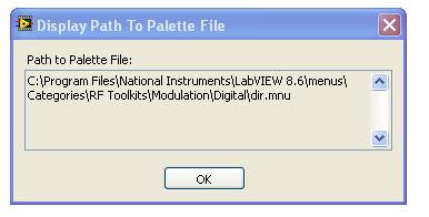
It seems that everything has been installed correctly, so I don't know exactly why this is a not complete automatically. I think we should try to manually add to the palette. I have included a link below that describes this process in more detail, you want to reference part "V. or pallets missing icons. You want to add the digital section to the palette by pointing to the file correct .mnu located in the digital file. I've included a picture where my .mnu as reference file. This should work for you, but please post back and let us know how it goes or if you have any questions.
Missing icons on the functions or controls in LabVIEW Palette
http://digital.NI.com/public.nsf/allkb/46E1672AB48C917D86256AFE00075436?OpenDocument
-
Calculation of derivative of clock for the NI 9234 module
Hello! I am relatively new to the use of material OR (and DAQ hardware in general), so this is probably going to be a really basic question.
We plan to use two 9181 chassis cDAQ with two modules NI 9234 sample data on 8 physical channels simultaneously at a rate of 25600Hz. As we use the 9181 chassis we cannot material synchronization as described in this topic:
«CDAQ-9181 will be out of the question because, as you said, it does not accessible PFI lines from the outside and you can not use a digital module for synchronization in a carrier case, because who was going to occupy the only available unit.»
We need the synchronization between the channels to be accurate to ±100ms. According to the http://www.ni.com/pdf/manuals/374238c.pdfspecifications, the time base internal master (fM) has a frequency of 13,1072 MHz and an accuracy of ± 50 ppm. I'm trying to calculate the maximum amount of the derivative of the clock, more than 1 hour. The selected sampling rate influence the result?
I think what meant Henrik was to connect the same signal to a channel on each of the two modules. This way, you have two digital versions of the same signal with each being scanned by a different clock. As long as it has the signal which can be identified in the worst case timing difference, you can determine that the sample [e] in a set of data has occurred at the same time (period a sample) as sample [k] with the other set of data. Then, you apply this synchronization relationship to all other channels in the two modules.
Strictly speaking, it is the difference in frequency between the two clocks, no drift. Data sheet specifies the precision of freqeuncy as +/-50 ppm, but specifies no drift at all. Drift has usually two components - temperature and duration. Drift in temperature is specified as ppm/degree, while the drift of time (also known as aging) can be specified as ppm per year. The two drift coefficients are usually smaller than the specification of the accuacy. It is not unlikely that the precision specification can include effects of drift.
If clocks drift significantly for the duration of your run, you may need to correct calendar several places in the data set. If the two chassis are physically close, any change in temperature will probably be very similar for both devices and aging is generally not relevant for periods of one hour. I suspect that the initial frequency differences are the only things that will be of interest to you. If a few ppm drift issues, let the two devices to heat for an hour before starting the test. This should be enough to stabilize temperatures.
Lynn
-
Can I create a task that includes the 2 c series modules?
I am trying to create a single task that includes 2 modules of the series C OR - 9425, but when I wire the constant "Mod3/port0, Mod4/port0" physical channel in the DAQmx create Virtual Channel.vi I get error-200086 which indicates the syntax range physical channel in the input string is not valid because several devices have been included in the chain. It is my understanding of LabView help this multidevice tasks are allowed. Also according to article KB http://digital.ni.com/public.nsf/allkb/CF85114C6025C84C862571C000722DDA devices multiple tasks are supported for devices of the series S, series C and DSA devices, and according to this article KB http://digital.ni.com/public.nsf/websearch/78E44565FD87E7D686257108007F94F8?OpenDocument I formatted my constant of physical channel correctly.
Please can someone explain why I get this error when all indications are that this should be a simple thing to do?
My C Series modules are in slots 3 and 4 in a chassis cDAQ-9188, I'm currently under LabView 8.5.1, with Windows XP
Thank you
Eric
Hi Eric,.
I am afraid that you cannot configure the hardware timing with the module 9425 in CompactDAQ. The NI 9425 data sheet explains: «the NI 9425 is a static digital module, so you can use it to perform only call by the software or static operations when installed in a chassis NI CompactDAQ.»
For I, AO and countertops, daisy chaining multiple calls to DAQmx create channel equivalent to specifying a list of physical channels, but it's different for DIO. Only one virtual channel DIO can contain several physical channels (lines). It would be quite reasonable to assume that by specifying a list of lines 'with a single channel for all lines"would cause DAQmx put all the lines in a single virtual channel, but see how it is implemented under DAQmx, is not possible when the lines are on multiple devices. Also, it would be reasonable to assume that if DAQmx could not put all the lines in a single virtual channel, it would create a virtual ring road, but that is not how it is implemented-, it returns the error you received.
Instead, here are two approaches to all 64 lines in a single task. Either we have to work.
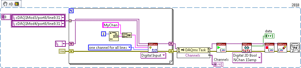
Approach: create a single task, containing two virtual channels (MyChan0 and MyChan1). MyChan0 contains cDAQ1Mod3/port0 / line0:31 and MyChan1 contains cDAQ1Mod4/port0 / line0:31. Digital 2D Bool NChan 1Samp read VI returns a 2 x 32 table of Boolean. To flatten it into an array of 64 elements D 1, you must use the table to reshape or some other method.
The task of DAQmx > ownership of channels is here to show that there are two virtual channels named MyChan0 and MyChan1. Also, I used a loop for to show that you don't have to encode multiple calls to DAQmx Create Channel. The constant "a channel for all lines" is redundant because it is the default value.
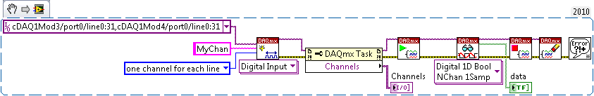
B approach: create a single task, containing 64 virtual channels (MyChan0 through MyChan63). This example uses the constant 'a channel for each line', which is not the default. MyChan0 contains port0/cDAQ1Mod3/$line0, MyChan1 contains cDAQ1Mod3/port0/line1, etc.. Digital 1 d 1Samp Bool NChan read VI returns an array of 64 D 1 of Boolean elements. If you have used the Digital 2D Bool NChan 1Samp VI instead, you would get a 64 x 1 matrix, there are 64 virtual channels with 1 line of each.
Brad
-
Double channel FP - TC problem
Hi, we have a problem with the FP-TC-J module, sometimes to the point of field is not perceived (MAX Returns a message "one or more specified attributes either do not exist..")
The first time I try to move the module and this work very well, I corrected the module and work.
The next day, the module have the same problem, I try to move without good results, we try to change the location of the module, but say MAx is not possible (seems this module is not known by the system).
My question is how is possible whether the module is bad?
Thanks for replying.
Hi Nicola,
the FP-TB-10 is designed to restart whenever it detects a new two-channel module since they are replaceable hot (quick flash of the indicator light). If there is an empty spot next to a module dual channel (a module HERE or AO and TC), FP-TB-10 Terminal Base may incorrectly detect that module dual channel. Since you have also two digital module, you can put the digital module next to the empty housing and see if that fixes the problem.
I would like to know if it works.
Best regards
Serena
-
I am currently using 6259 PCI which has 2 outputs of meter. Are there signs of counter that I can add to get a 5-8 additional counter output? All those I see on the Web site of NOR and Measurement Computing have two outputs maximum.
I like the idea of a low cost with meters USB device. If you have the chance to remember to fill a Product Suggestion to help us prioritize, maybe it's something that we could look at if demand is high enough.
In the meantime, you can watch in 9174 chassis that just came out 2 days ago. It uses the same chip of STC - 3 as our X-series machines, so there 4 counters available on the chassis backplane. To access outside you will need to use a digital module as the 9401.
The 9174 connects to your computer via USB and is programmed with DAQmx (support added in version 9.0.2).
Best regards
John
-
[FPGA] - NI 9401 - entry & exit issues
I'm trying to put my input and output on digital modules NI 9401 channels on my compact RIO to power a photogate and read the entry in the module. However, my FPGA code does not work because the way I expected... as my output does not raise my 5V expected and I don't get anything in my driveway.
I have put my lines you want at the entrances and exits and have power for my photogate to my entry on DI5 and two game I should get a high through my comparsion and et0 value. It would then turn on my LED on my front.
First, you should define the directions of the line outside of the big loop, power your device with your NOT then see if your DI rises.
Then your code seems not to be read or set all numerical values, since you use the reference stations not the terminals of the digital value.
So in fact comparison is always false (you compare two references).
In my case I had errors in my EDS file. Basically the slave device was not defined for the correct number of bytes of input/output in the EDS, i.e. a wrong configuration file. To fix this I had to change the EDS file.
Edit the file EDS
To change the EDS file, I used EZ-EDS , which is a freeware, devicenet specific EDS editor of ODVA.
I did my corrections and saved my file EDS. (After having saved my original, of course).
Remove the installed Labview EDS file
I restarted LabView.
I went through the steps above again and loaded my new EDS file.
I saved the project and came out of LabView.
I rebooted the computer and the slave device.
I restarted the project and launched a VI.
I was able to communicate with the device. That is something that I had not been able to do before. And, in doing so, I discovered how the device speak and why were not each module. (I have a standard for my block devices EDS file, as it appears that LabVIEW is not capable of a modular system that requires an EDS file for each module. I could be wrong on that last part though, as there may be a setting on my real device. But it is unecssary in my project. So I do not consider this further.) Because I was using a standard file of the EDS, only a single slave device showed, and so the data for each module are in the stream of bytes returned to the DeviceNet network. Addressing each module is a question of analysis the bits and the bytes appropriate.
Thank you
Tennessee Paul

Maybe you are looking for
-
I can't connect to the xbox live via the xbox or on the internet.
I can't contact xbox live support because it tells me that there is an error whenever I reach the site. When you try to find a connection to xbox live, it tells me to go towww.Xbox.com/servicealertOnce again, unable to connect. That's what I find whe
-
I was on a site and it all of a sudden got really big and then now here when I was installing this this question use this form got real small but the other was still great
-
How can I get rid off the coast of spam in my junk mail?
original title: Spam in spamHow can I get rid off spam in my junk mail, I have nevr requested?
-
Hi can help someone, after clicking 3 times on my g6, I get the 53183358 code
Hi can help someone, after clicking 3 times on my g6, I get the code 53183358
-
Hello I get a 0XC4EB841A message on my jet 3050 J610a Office. The power button! and cartridge all Flash. I followed all the steps of TS listed on HP. I can generate the 12345 reflash message when I press and hold all three buttons to one side and c