DLL to control a relay
Hello
I have to automate a testbed project of end of studies, I do so my first test with Labwindows. I apologize then pour any question which you think beast.
Pour to generate a voltage of 5V (high level of the United Nations and a low level) pour Commander relays, I need a dll into the testbed "module" as well as a call to a specific function 'function Call '. At the beginning I thought about writing a value to the digital output on my card (PCI of NI 6509) provided in "Find examples" (WriteDigChan.prj) but it seems that the use of a dll is essential. Can you help me find this dll.
Kind regards
Hello, PFE,.
First of all, this forum is in English so for answers it is better to post in English.
Pour with this project it will take:
-perform a function in CVI, test it and verify that it works well.
-And then call this function in TestStand using the step type 'action' with adaptar CVI. (it will go the necessary arguments defined during the creation of the CVI function)
Kind regards
Tags: NI Software
Similar Questions
-
Different signals controlled by relay... we want to show only the "chosen" signal
Hello
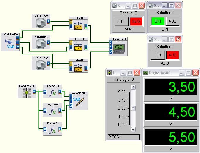
I have the following program:
Explanation of this little program:
I have 3 different signals recorded in variables:
Variable 1: the tension that comes from the 'hands-on' + 1, (according to the formula interpreter).
Variable 2: the tension that comes from the 'hands-on' + 2, (according to the formula interpreter).
Variable 3: the tension that comes from the 'hands-on' + 3, (after the formula interpreter).Then these Variables are read and they can pass (enabled) randomly by switches, (this is just an example). In the actual program, only one relay can be activated, NOT 2 or 3 at the same time. (This program is only a part of a main program, control of the relays come from the other part of the main program).
OK, now, we start the program: in the second 0 (departure), the 01 relay is activated (the other not); and, for example, in the second 10, 02 relay is activated (and relays 01 disabled). Pentecost, I want to view, or "do" the following: 4.5 V of the second 10, 0 to 9 and from the second, I want to get 5.5 V of the same line, (because this tension will be the output from my main program', is - it possible?)
Thanks for your help,
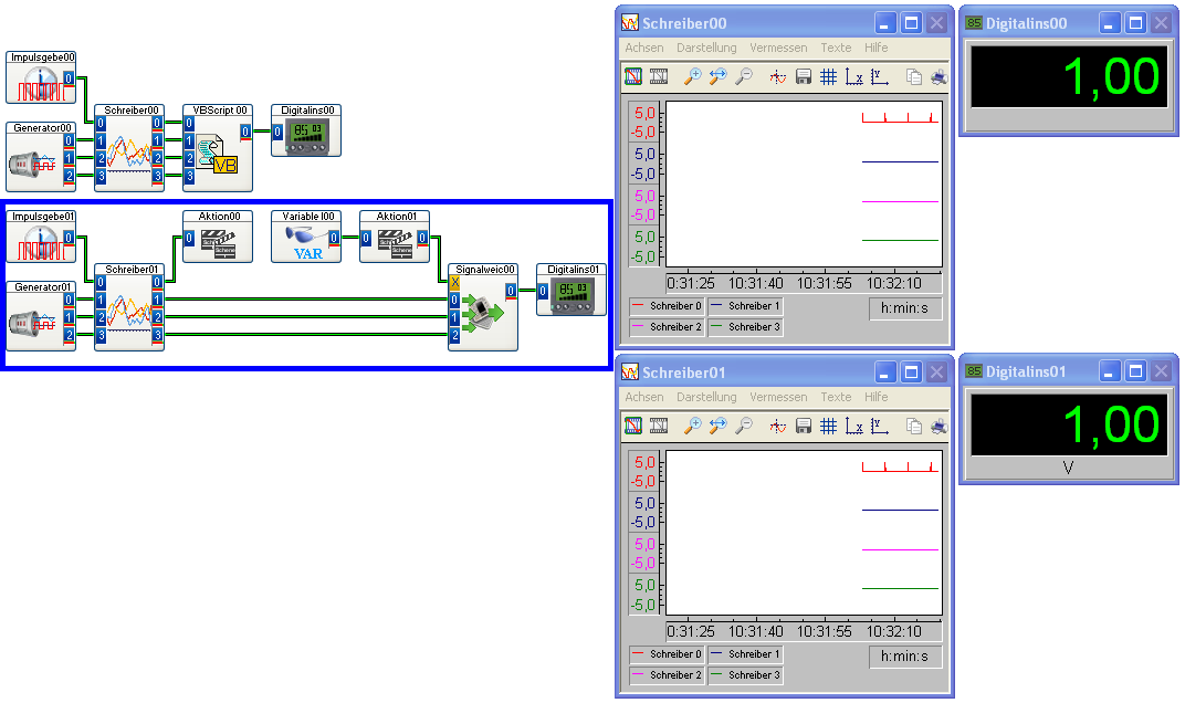
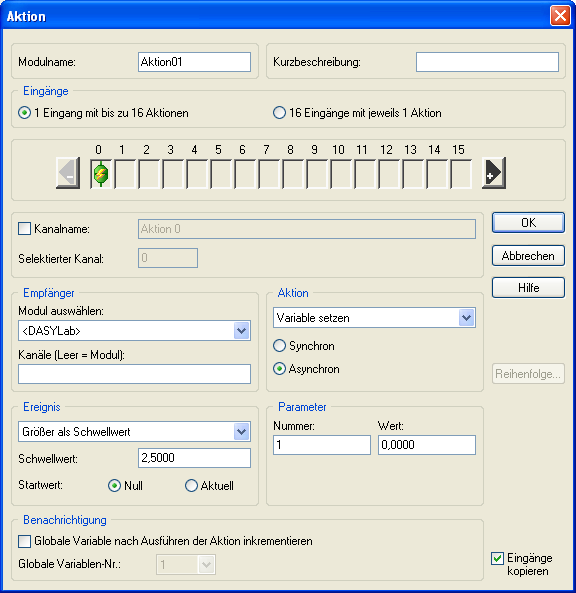
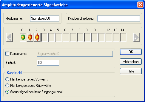
ArterOption 2 - based on standard modules DASYLab, but a lot of things todo.
See the blue rectangle area of worksheet.
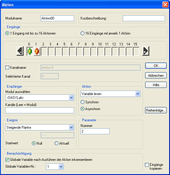
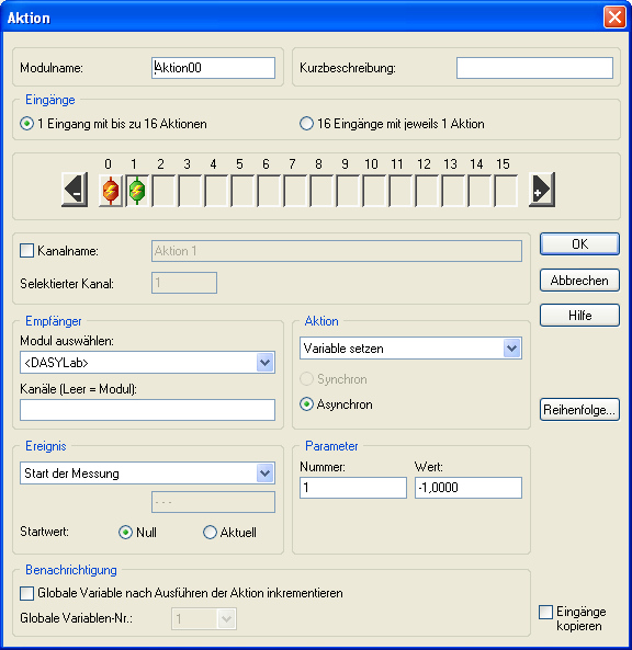
The Module Aktion00 define any action of 'Dummy '. Important is that with the arrival of action that would increase the Global Variable 1.Initialization with departure of spreadsheet for the 1 Variable Global opportunity
Global Variable 1 2.5 >-> then we reset to 0.
Best regards
MHa
-
11.0.07 blocks the acropdf.dll activex control in the application of part 3
Hi, we use a piece of software that uses the library acropdf.dll - update of Adobe Reader (any version of Windows) to 11.0.07, software that uses acropdf.dll crashes as soon as it tries to display a PDF file (citing acropdf.dll as the module that failed) - roll back to any previous version of Adobe Reader solves the problem. (Same 11.0.06 works very well) - this was repeated several times on different machines and different versions of Windows, all with the same result.
Is this a known issue with the 11.0.07 latest version?
Thanks in advance.
For those who can still access their VB6 source code - replace the PDF control with a web browser control and in turn all the events of pdf.load with the web.navigate event - this effectively avoids the problem by forcing the PDF file appears on your form within the browser control. I have now deleted all references to the PDF control in the project, and only use the web control - overall it feels much the same operation.
(Started the re-written in VB.net now if...)
-
Control relay with Boolean switch using DAQ assistant 9481 - problems
Sorry for what may be a stupid question but I'm stuck in quicksand.
I use a relay module 9481 and have two external relays connected lines 0 and 1.
When I create a digital output 0 line by line, I can run the test inside the express and activate the relay and turn off without problem.
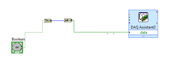
The generated block DAQ expressed expects a Boolean input of 1 d. (See attached photo).
I want to connect a Boolean switch relay line disk 0. You can connect live not because the switch is Boolean and the input is Boolean 1 d - I'm a conversation in the pict.
All plumbing lines display results, the relay never active.
Any bunch would be greatly appreciated! Thank you
Mr._Mechanical,
Welcome to the Forums of switch OR this forum is generally intended for products OR-SWITCH [such as the NI PXI-25xx & NI SCXI-11xx], I think I know the answer to your question.
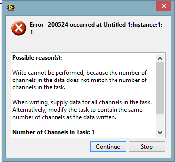
I think the reason why it's a failure is the conversion you make generates a table of 16 Boolean [as the 'boolean to (0,1)' function creates a data I16 type] with your data more false data points 15.
When you try to control the relay, he sees 16 datapoints are you Commander to a single port [channel] and so error out.
My suggestion would be to use normal DAQmx digital output screw [with, he set up as ' Digital > single channel > single sample > Boolean (1 line) "] rather than the DAQ assistant.
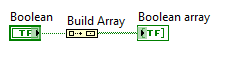
If you use the daq assistant, simply by using the function 'Building the table' will transform your simple Boolean data point in a Boolean array containing a single element.
While the DAQ assistant is very easy to use, I recommend that you use the DAQ assistant, because this reduces the features and increases the execution time.
-
Problem setting up base appeal of the DLL (win32 API?) for the control of coherent laser Verdi-G
I'm trying to set up a call to the DLL to control a coherent laser Verdi-G.
I can't know the right way to set up calls. In the attached Demo.cpp, there is a function "RunTests". It's kinda my final goal. Functions send some commands to query the device. I'm going to need to send commands like this (along with several others, some of which take arguments... but I think I can understand that on mine)
My problem is getting started. I can't even talk about the device. I tried a few different ways to set up the call to the DLL, but they have always will plant the computer. I don't know if I am missing a few parts such as the initialization of a method to speak via USB or other parts.
I added my own .vi tries as well as some of the .c, the .cpp & the .h files associated provided with laser control software. I may have missed the relevant records; I'm happy to add them if someone sees a necessary file / referenced.
Any help would be appreciated.
Thanks for your time!
Turns out I missed the included .vi which belongs to install them the package. I was looking directly on their CD.
I would mark this closed if I saw a button for this?
-
Hello
I have a problem to control the relays i advanced to two loops for the relay a solenoid to control and other control fans. loop of solenoid should work when the fans stop. I am unable to control loops or maybe my developed logic is incorrect. Please, any body help me with this. I am using pxi2586 equipment.
Thank you
Shaik
-
set the duration for the nor 6501 to control relay
Hi all
I made great progress thanks to your help. Now, I know how to control the relay using NI 6501.
Furthermore, I try to put in place a period of time (after two hours) and leave-6501 OR turn on the relay.
What kind of example I can refer to?
When pressure data are weak to 1mtorr, then turn on the relay is another control.
If there are some I can refer to similar examples, it will be useful for me to programming
Thank you
-
6008 daq digital outputs to control relays
Hi all, I'm looking to help create a VI to send out digital to a daq 6008 to control relays. What I'm trying to do is when you press start and a condition is met send a digital output to control a relay for 30 seconds or so to take a measured voltage to be taken an analog voltage. After 30 seconds, I want the first relay to switch off and the next relay lights for the same amount of time. I want to continue this sequence to 7 readings, blood for every step and send the data to an excel file. I know it's basic stuff, but my experience with labview is limited! Any help would be greatly appreciated.
Thank you
Paul
Hi Paul,.
I looked on your problem this afternoon and I agree completely Fan Ravens that the state machine is in fact the most appropriate architecture for such a task of data acquisition. A state machine architecture is one of the most commonly used in LabVIEW design patterns and is especially suitable for any program where you have clearly defined the steps that can be represented by the States and rules for the transition between these States.
There is a model of Machine of State Standard contained in LabVIEW which should give you an idea of the underlying architecture and is a good starting point. To give you a better idea of how this architecture can be applied to a data acquisition task, I would recommend that you look at This example. Although States will be slightly different in your case, this should provide you with a good understanding of how you can architect such a request.
I hope this helps.
Best regards
Christian Hartshorne
Technical sales engineer
National Instruments UK
-
RELAY CONTROL WITH THE HELP OF USB-6008
Hi all I'm new to labview, I want to control the relay using USB-6008. could someone help me find valuable solution, because this is my final project mechanical engg. I need the electrical diagram and whether it is digital command also mention details of ports/lines I have to connect.
In this, I joined the relay diagram, in which I have to just to magnetize this nucleus to attract this soft iron. so I need to do ON and OFF. Please guide me and thanks in advance too.
-
the parameter mapping constant to a control block Veristand simulink block
Hello
I'm trying take a simple model of an RL circuit in simulink (build a DLL) and control of the constant blocks in Veristand to dynamically change the value of R and L constant through Veristand Slider indicator or digital. I can see the output of the model run, based on the initial values that I have loaded, but I'm not able to mapping of these parameters to any digital control.
Any thoughts on how to do this!
Hey, Trever,.
You must use a command of calibration model to interact with parameters, and not a digital control.
Take care!
-
Call a DLL in TestStand by reference
All,
I developed a DLL that control a USB based power. The call of the dll works from TestStand 4.1 most of the time. What I think is happening, is that whenever I call the dll in my main sequence of the file as well as other files in sequence, as several instances of the dll is loaded.
Part of the init of food must pass back a SESSION number that is used in subsequent calls to the dll. I store as a global variable in TestStand and pass around sequence that never he needs.
How can I load the DLL at the beginning of the sequence and PASS a reference (handle) to all other calls to the dll?
Thanks in advance
Carmine
Doug,
Thanks for your help. I found a UnLoadModules() in one of the child seq that I missed. Unless I missed all the others, I think this should be resolved.
Carmine
-
I want to order two relays, but Labview says that I have something wrong with my VI
Of the image, I have 2 control relays, they are the two toggle switch type, I want to control at the same time, but fail to do so.
I already have digital > channels > single sample 1 > Boolean (1 line per channel) and before I run it, I choose the channel 0 and 1 in the front panel
When I run it, the program does not give error, however, I use a voltmeter to test the voltage on ports 0 and 1, they are 5V and stabilize... which does not correspond to the VI I write
After you click stop, Labivew said:
read name or write operation failed because the number of rows in the data of a string is not the lines in the channel.
If you use the digital waveform data type, make sure that the number of lines in the digital waveforms is the number of lines in the channel. If you are using Boolean data, make sure that the dimension of the array for the rows of the data is the number of lines in the channel.
Number of lines in the channel: 8
Number of rows in the data : 1Task name: _unnamedTask<4>
What is the problem with my VI? Thank youHe doesn't seem to like the layout of the table 1 d Boolean. It is not sensible.
But I found a way so that it will run without errors. I don't know without having a real DAQ hardware whether outputs will be correct.
1. change all DAQmx wrote on the Board of Boolean 2D, (N lines per channel). If Digital > multiple channels > sample > Boolean 2D.
2. change all the raster constants to add a dimension turning them into 2D Boolean tables.
Now, it will run without error. But if the output is correct or not, you need to test.
You said you want to control the relay. I don't know what kind of relay that you have, or is that your DAQ hardware, but take keeps most of the DAQ cards do not provide enough current to directly drive a relay.
-
Using NI 6211 to drive a relay
Hi, I have a problem and I hope someone could help me. I am currently using an NI USB-6211 with Labview 8.6 box and want to order a relay. The relay (see attached PDF) will close the side secondary (30 V, 3 a) when the primary side is a current of 5 my voltage of 3 V. Since the only analog output can provide 2 my trying to use the outputs digital, but I don't know I'm doing things.
So, my questions are:
(1) is it possible to control the relay with the box USB-6211 or do I need to connect some extern?
(2) if possible, how can I connect to + and - wire on the primary side of the relay?
Best regards
Mattias
To control the relay, you can use one of the four digital outputs of the 6211. They are supposed to sink and source 16mA.
Your relay needs 80mA (more than the spec allows sucking of the 6211), so you have two options:
Use a SSR (solid status relay), they can be powered directly from the map
Or use an external power supply
Be careful with this relay you have! Miss me the free led running on the solenoid. * PENG LAUREVENT *.
-
activation of the relay using rs 23
Is there any sign of low cost in which a relay can be activated through labview with rs 232 communication. Please let me know as soon as possible.I need to acivate for a 5V with a labview timer relay and it should be communicated via rs 232 for the relay card.
Looking to change your relay specifically by RS232, or simply by using the serial port?
If it's the latter, then take a look at the "Troubleshooting Serial Line Monitor.vi" in examples of LabVIEW. With this, you can control the DTR (4 pins) and lines RTS (PIN 7) of your serial port and use them to move from a transistor or FET to control your relay.
-
DAQmx and SCXI-1160 with 'DAQmx switch Open Relays.vi '.
Hello
I use DAQmx to pass the baton on a map of SPDT 16 SCXI-1160. When I run the 'DAQmx switch Open Relays.vi' with the entry "ch0/SC1Mod1 / ' I think the relay normally open position 'NO '. But this is not the case, the relay is in the position of the NC. Here are the steps I do a simple VI.
1. define the topology of the 'SC1Mod1' to '16/1160-inverter.
2. call the 'DAQmx switch Open Relays.vi' with the string "/ SC1Mod1/ch0.
3. then I take a physical measurement, with a multimeter on the SCXI-1324 terminal block and the relay is in position "NC".
4. If I run the "DAQmx get relay switch Position" he's back "Open"!
Is this the good behavior, and if so can someone explain the logic behind it.
Thanks in advance,
Michel
Hey Michael,
Sorry, I didn't know that you were actually able to control the relay and you receive just the reverse logic. To answer your question, on the SCXI-1160 module, there are three connections for each channel: COM, NO pine and pine of NC code. Reset, COM is connected to the spindle of the NC. When you issue a command to OPEN channel 0, COM will stay connected to the NC pin, even if the software indicates now that the PIN is open. When you issue a command NARROW-gauge 0, COM will be now connected to pin number and not on the spindle of the NC.
A better way to think of it, is to focus only on the relationship between COM and no. pine. When you send a BLANKET order, this connection between COM and no. will be open. When you send a CLOSE command, the connection between COM and no. will be closed. Consult this manual for a visualization of how this switch is set up: http://www.ni.com/pdf/manuals/320513b.pdf. Refer to page 2-9 and 2-14 of this manual for pinout.
-Nathan H

Maybe you are looking for
-
As I installed the latest OS 10.0.1 on my iPhone, the Pandora app does not work.
As I installed the latest OS 10.0.1 on my iPhone, the Pandora app does not work.
-
I'm not too familiar with the configuration of current storage of the Mac Mini. If the reader of the merger is not a true merger but combines a PCIe m2 with a HARD drive. However, I would like to know if buy you one that comes with a PCIe SSD out of
-
Hello This thread is based on my post in the exchange of ideas of LabVIEW. I put my screw in the .rar file attached. Concerning Marc
-
Cannot activate Windows XP after motherboard change
I had to adapt to a new motherboard and cpu after the cpu has failed and a 'repair installation XP', now when I click on 'Yes' to activate the wallpaper is displayed but no activation screen. That leaves us stuck.Is my disk XP home SP2, but we had do
-
Hi, the trial of 8.1 windows installed on my PC laptop HP 14-d003tx expired already so I installed a new windows 8.1 Pro 64 - bit OS. I went here: http://support.hp.com/us-en/drivers/selfservice/HP-14-Notebook-PC-series/6529958/model/6753958 to check