6008 daq digital outputs to control relays
Hi all, I'm looking to help create a VI to send out digital to a daq 6008 to control relays. What I'm trying to do is when you press start and a condition is met send a digital output to control a relay for 30 seconds or so to take a measured voltage to be taken an analog voltage. After 30 seconds, I want the first relay to switch off and the next relay lights for the same amount of time. I want to continue this sequence to 7 readings, blood for every step and send the data to an excel file. I know it's basic stuff, but my experience with labview is limited! Any help would be greatly appreciated.
Thank you
Paul
Hi Paul,.
I looked on your problem this afternoon and I agree completely Fan Ravens that the state machine is in fact the most appropriate architecture for such a task of data acquisition. A state machine architecture is one of the most commonly used in LabVIEW design patterns and is especially suitable for any program where you have clearly defined the steps that can be represented by the States and rules for the transition between these States.
There is a model of Machine of State Standard contained in LabVIEW which should give you an idea of the underlying architecture and is a good starting point. To give you a better idea of how this architecture can be applied to a data acquisition task, I would recommend that you look at This example. Although States will be slightly different in your case, this should provide you with a good understanding of how you can architect such a request.
I hope this helps.
Best regards
Christian Hartshorne
Technical sales engineer
National Instruments UK
Tags: NI Software
Similar Questions
-
OR PXI-6289 Digital Output Solid State Relay
Hello
I try to control a mechanical solenoid pull using a relay of sold State connected to my PXI-6289. Currently I have the CRDD connected to Port 1 line 4 and use the code provided here http://zone.ni.com/devzone/cda/epd/p/id/6411 . However, every time I run the code, the light on my SSR (wired to show the logic works http://www.adafruit.com/products/268) does not illuminate indicating that there is no signal to be output. Any help in this matter would be much appreciated. If additional information is needed please let me know.
Best,
Brad
Nevermind, problem solved it was just low power.
-
digital output to control three motors
Hi all
I am a newcomer in the field of control. I have the following problem. I try to control 3 units using a NI USB 6215. So I connect 3 led to the line 0, 1, 2 and I adapt a Labview example in my case. The problem is that only the first case (I mean directed first case) works correctly. I select Motor_1, I gave the command, and the led is lit for the period specified and OFF at the end of this period. When I try to do the same thing with the number of led 2, I select the Motor_2, I gave the command, the number of led 2 is lit during the period indicate, turned OFF at the end of this period, but at the same time begins the number of led 1 and is all the TIME (he must be OFF). However, in the case of the led number 3, when I gave the command sequence is correctly executet during the specified period, but at the same time, the two led 1 and 2 start and are all the TIME. At the end of this post, I would like to thank Altenbach of the Knight OR for the display of a fine example of veriy (Volume Dispensiion in 2008).
Thank you all for reading this post (and the final solution)
Try this... I don't like express VI

-
DAQ digital output default to low Earth
Hello
This probably a basic question, but I have found information on this subject.
When I connect a data acquisition unit (usb6009) to the USB port I get any output defaults to a high (+ 5V) until I run my program and I put them to lower ground.
Is it possible to configure default data acquisition always at 0V?
I enjoy any comments or links on how to change this.
Thank you
Cristian
The default value for the 6009, is that they are all set for entries. What you see is the pull up. But, no, you cannot set the power of the State to the 6009.
-
NI USB-6009 digital outputs are active when connected to a PC - I'm not that
I have a small problem:
All outputs digital NI USB-6009 module become active when the module is connected to a PC when no VI is running.
As soon as I start my VI, which controls the module, all the outputs are disabled (now inactive).
How can I achieve this, outputs are inactive if the module is connected to a PC with no program running?
johanneshoer wrote:
I have a small problem:
All outputs digital NI USB-6009 module become active when the module is connected to a PC when no VI is running.
As soon as I start my VI, which controls the module, all the outputs are disabled (now inactive).
How can I achieve this, outputs are inactive if the module is connected to a PC with no program running?
The USB-6008/6009 case has a pull-up internal (4.7 kOhm) resistance. This causes the outputs digital on the device to have a startup logic high State. t is not recommended to use some sort of resistance of menu drop-down. However, what you can do is add octal buffer like the 74HC541 stamp and a digital output to control the sorting of the 74hc541 state mode. Connect the OAS and CEO input signal. A Summit on the pins of the latter will be sorting the output of the buffer State. Therefore, no output signal will be present until you pull the stems of low control. The USB-6008/6009 case have a 5 volt output (200mA max), you can use the buffer.
-
Control relay with Boolean switch using DAQ assistant 9481 - problems
Sorry for what may be a stupid question but I'm stuck in quicksand.
I use a relay module 9481 and have two external relays connected lines 0 and 1.
When I create a digital output 0 line by line, I can run the test inside the express and activate the relay and turn off without problem.
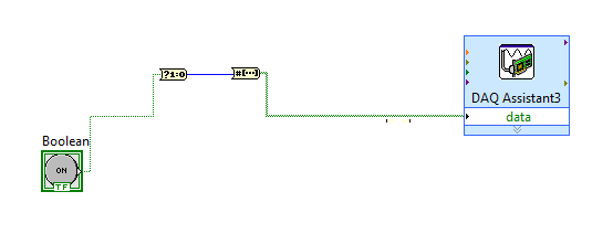
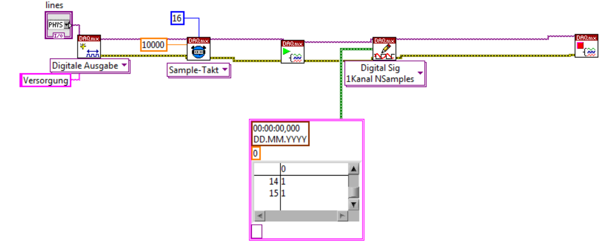
The generated block DAQ expressed expects a Boolean input of 1 d. (See attached photo).
I want to connect a Boolean switch relay line disk 0. You can connect live not because the switch is Boolean and the input is Boolean 1 d - I'm a conversation in the pict.
All plumbing lines display results, the relay never active.
Any bunch would be greatly appreciated! Thank you
Mr._Mechanical,
Welcome to the Forums of switch OR this forum is generally intended for products OR-SWITCH [such as the NI PXI-25xx & NI SCXI-11xx], I think I know the answer to your question.
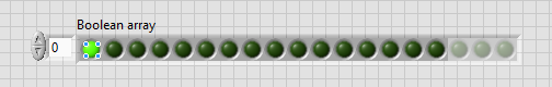
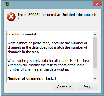
I think the reason why it's a failure is the conversion you make generates a table of 16 Boolean [as the 'boolean to (0,1)' function creates a data I16 type] with your data more false data points 15.
When you try to control the relay, he sees 16 datapoints are you Commander to a single port [channel] and so error out.
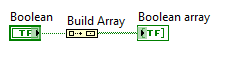
My suggestion would be to use normal DAQmx digital output screw [with, he set up as ' Digital > single channel > single sample > Boolean (1 line) "] rather than the DAQ assistant.
If you use the daq assistant, simply by using the function 'Building the table' will transform your simple Boolean data point in a Boolean array containing a single element.
While the DAQ assistant is very easy to use, I recommend that you use the DAQ assistant, because this reduces the features and increases the execution time.
-
USB 6008 digital output signal
I am VERY new to LabView and have been racking my brain trying to get digital output of my USB-6008. All I want is to be able to get a signal of + 5 V of my digital output when I click on a button. This signal opens a valve on a system I see so when it is pressed, it must stay open until I press the new button. It seems simple enough to me, but I'm not too familiar with LabView. Help, please!
Stripling07
You must first take the LabVIEW tutorials and then look at the links to get started with DAQmx .
The simplest program would be with the DAQ Assistant. Drop it on your schema, and then select digital output > digital line. Select the line when the wizard has completed, click OK. Wire a Boolean value in a table to build and the output of which is connected to the data entry. That's all. You can test the output of MAX (Measurement & Automation Explorer) with the test Panel. Do NOT test with your connected tap. Your valve may require more current that can provide the 6008.

-
output voltage DAQ for external device control
Hi all
I have been using LabView 8.5 to acquire data from an acquisition of data USB Multifunction (1608FS of MCC DAQ) module. However, I now want to use this device even for controlling an optical shutter, but also to detect the position of the shutter sensor. Is it possible using this device in LabView?
I had no problems on the side of the acquisition but I was not able to generate any output voltages can any body in this case help.
Concerning
Steven
According to my quick google search, this device is listed as
DAQ module with eight 16-bit analog inputs and eight e/s digital
So there are no outputs only digital outputs.
-
USB-6008 to give the digital output
Hi all
I was wondering anyone at - it base an example of an exercise using USB 6008 to give a digital output of a VI in Labview.
I am very new to the use of the USB 6008 AND Assistant DAQ and so far I've had reading a temperature, next step is I want the USB-6008 to give a + 5v output when the temperature reaches a certain value, I built a Labview 2009 VI for the temperature reading, but now I'm stuck on this piece.
Any help is appreciated! or if there are examples of laboratory exercises that exist that I can perhaps draw.
Hi Marko
Please take a look at the link that has some interesting and intuitive video to use the USB-6008 housing and how to set up the device for several applications in LabVIEW below. Please take a look at the step by step videos and let me know how you go. They are under the tab '"virtual Demos.
-
digital output without DAQ Assistant
Hello
I can produce a digital output signal of some sampling rate 10 kHz with the acquisition of data-assist. Now I would like to implement the same functionality with normal DAQ - screw, as I have to synchronize serveral exits lateron. However, I failed get the normal screws so that they work as the DAQ assistant. The most important thing is out the arbitrary signal with 10 kHz.
Thank you.
Thank you very much. The idea of watching inside the acquisition of data-assist helped.
-
NEITHER 9205 digital output configuration with DAQ Assist
Hello
I have two NI 9205 Analog Input Modules which I have configured to read from each of their 32 channels. I used the DAQ Assistant help generate the vi which contains the task out - DAQmx event and also the DAQmx Read vi.
I used the Wizard twice, once for each module 9205 and then put the playback functions in a sequence structure so that only read would be carried out at the same time. It all works very well!
Now, I want to add in the code to wait in a loop before all loop containing playback functions, so that the user can press the GUI to send a logic 1 to the unit under test, and after it is sent immediately starts collecting data.
The DAQ Assistant Help does not recognize the module 9205 when I try to set up a task to write a digital output. 9205 a 1 digital output so why is the wizard does not recognize this? I also tried to create a task manually, but I got stuck.
Someone please help. I can reach the source if needed, but I thought that the descriptions above were sufficient.
Thank you
Gary
Hello
You are right it shows a line in this user manual, and in fact, you have found an instance where an important piece of information was left out of the documentation. This digital output line is actually only available when you use a cRIO chassis. It will not work with the chassis for the acquisition of data compact 9172. Here is a knowledge base that explains it. I'll also go ahead and file a request for corrective measures so that this note be included in the next version of this manual. Thanks for the comments.
Chris
-
Control the Boolean commands and generate a corresponding digital output
Hi all
I'm working on a project of activation of the electrode, here, I thought that how could I order an electrode in a time and generate a digital output of it accordingly. I want to replace it with each electrode with a LED on the front panel and generate a numerical value to each LED on the block diagram.
If it can be divided into two parts
1 control the Boolean outputs
Here, my goal is that if I have 5 leds that are used as a Boolean control, must be ordered so that only one of them lights up at the same time and the rest goes off.
I mean for example if #3 was turned on and that the user pressed the #3 #2 should be turned off and only #2 lights.
2. generate the corresponding numerical value
Depending on the position of the LEDs I want to generate a corresponding numerical value, as previously released 3 coming and exit 2 then comes when the second LED illuminates.I ask all participants to this group to help me with this.
Concerning
Why don't you use the radio button control? You can replace the boxes if you want the buttons.
-
Maximum speed of digital output of the DAQ 6009
Hi all
I'm trying to generate a clock the digital output on my USB DAQ 6009 puse. The maximum frequency, that I was able to produce was 0.5 kHz, but I would like to generate at least 1 kHz. I HT wired port0/$line0 of the OID of data acquisition to the data acquisition ai0 and attempted to read the output via the input of an analog of the same device. I have attached the programs here. Don't know if it's right. You can help. Thanks in advance.
150 s/s is the maximum rate of the analog output. The 48kS/s is the maximum rate of the analog input. Read a little more closely.
This unit will not do what you want. I recommend putting the hand of your representative local of NOR and discuss your needs with them. They should be able to set you up.
-
How can I write a digital waveform to the digital output (traditional DAQ)
Hello
I use a NI 6023e, PCI, with 8 digital outputs. I generated a digital waveform. How can I write for a specific digital production line now?
I only have Labview 7, so I can't use DAQmx.
Thank you very much
-
Digital output is not 5V when connected to a circuit
I have a very simple circuit I want to operate a valve. I have a NI USB 6008 with 12 digital i/o ports, a KF0602D solid state relay, 12V power and a solenoid valve.
The idea behind this circuit is pretty simple: use a digital line of the 6008 to close or open the switch in the KF0602D. With the switch closed, current flows from the power supply through the switch, to the valve and that opens. When the switch opens no current flow and the valve closes.
When I plug my 6008 in the KF0602D, however, my 'high' digital output falls from 5V to 1.73V. It's a problem because my switch requires at least 3V to close. I don't know why the voltage decreases because the relay is supposed to just on 3mA current with an input 5V, wells in the area of the specs listed 6008. What can I do to make this work?
Outputs digital USB-6008 are drain opened with pull-up 4.7 kohm resistors. This will NOT lead your SSR entry requiring > 2 my.
He must reverse the polarity of your control signal. Wire-entrance of the Republic socialist Soviet to the line of the 6008. Wire the + input of the Republic socialist Soviet to + 5 V. Then you have the 8.5 my driving ability to do what you want.
Lynn

Maybe you are looking for
-
The program began OK when I installed on the new computer. I could add my account and to download the incoming mail. I got a big file (8 MB) profile, much saved messages and a big address book as well as several other accounts (work, club, etc.) I ne
-
Satellite A10: Modem - no dial tone error 680.
Hello Seems to be a common problem search the ends of the net even if I have to find a solution.No dial tone error 680. Satellite A10 running Windows XP SP2.Interviewed modem-It's ok.Check wait for the tone. still not connect.Have tried different tel
-
Suddenly, when I use my computer to get on the internet, I hear a thud. It happened once before, but suddenly disappeared. I wonder if the fan may be bad. Any ideas on what is the cause? The only other time that I hear it is when my computer is near
-
Impossible to find accessories
I am running vista Home premium. When I go to start programs, I'm unable to find accessories. Any suggestions