Exceeded the output signal analogue of sbRIO9636?
Hey people so I got my sbRIO9636 of the sbRIO assessment package.
I was wondering if it is possible to transmit a signal from smulated via the analog output of my FPGA.
Basically, I have 2 signals I want to simulate who go to the analog output of the FPGA in a multiplier amplifier (this is a physical IC).
However, whenever I try to transmit the signal simulated in my output analog I get an error because the signal is 2D for the analog output is just a fixed point. Is there a way to get around this?
Hi Butterwaffle,
As noted Nick exit FPGA is point by point - you can write a single AO to both sample.
This is probably a good place to start:
Tutorial: Generation of signals with CompactRIO
http://www.NI.com/white-paper/4783/en
Hope that helps!
Tags: NI Software
Similar Questions
-
Change the shape of the output signal without initializing the new process of output signal
Hello!
How to change the shape of the output signal produced on the output channel without initializing the new process of output signal?
Thank you
Yes, you can do the same thing without count/killing the task all the time.
Attached VI shows how to use redeclenchables AO in the same way, using a meter like time base for the AO.
Please note that attached VI uses the same Subvi as in the example you posted before.
Christian
-
Why the output signal is pulled up to stop the program in RT
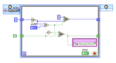
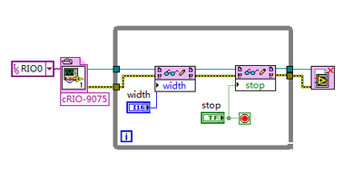
I use 9401 output a PWM signal. When I run the program FPGA and the stop, it does nothing statement. BUT when I run the program through RT using the compiled bitfile and stop, there will be a high level of 110ms.
Here's my diagrams FPGA and RT of a simple signal output.
I wonder why this could happen? Should I observe all specific during the programming of the RT?
Thanks in advance
You can add logic to ensure that the output goes low when the judgment is TRUE within your unique Timed Cycle loop. My guess is that you just see a delay between when the FPGA is ordered to stop and when the file bit is actually closed and the FPGA is reset.
-
Output signals controllable DAQmx (real-time)
Hello:
I have a question here.
It is quite difficult for me, and I can't find any bad example and discussion.
Hope that some people give me some information for me to look it up.
--
I am trying to generate an analogue signal into a DAQmx device (I have an and uses it well) to control another device.
The output signal must be the sum of a background signal (which is decided, let's say a sine wave) and another control signal.
The control signal depends on the entrance of real-time control, for example by using the horizontal location of the mouse to the value of the signal.
The background signal is designed in advance and it will run continuously (should not be stopped once the system starts to ensure that synchronization between each devices).
At the same time, the control signal should be continuous. (if there is no new entry, it uses the default value or the last entry).
--
I have almost no idea on how to do it.
As far as I know, needs only one daq task to write the signal, and then she runs after.
The control signal is a thing in real time, so the task needs to be updated very quickly.
But regeneration tasks cost 50ms ~ on my computer (and I used the low levels rather than the DAQ assistant Renault).
Also, in this case, my background/control signal will be be stopped every time that when the task is regenerated (and this makes my synchronization failure.)
I checked DAQmx in real time, but couldn't find a few examples of tris and seems it isn't for my application actually (?).
A possible solution, I came is cascading my two signals once they are generated by my DAQ hardware. And then I can use an a/o to be the background signal and use an another a/o to be the control signal.
However, my control signal is always interrupted between each loop, and the method of external cascade seems not smart.
Or data acquisition is not perhaps suitable for this application?
--
Hope that some people give me some information and then I can check their.
Thank you very much
Hi Jhensi,
How the example provided was for you?
With respect to the delay that you experience, there is always a slight delay incurred as a result of underlying driver DAQmx running in the background.
In addition, your USB 6611 will have inherent delay due to being used as the communication protocol USB bus. There may be up to 100ms latency in some cases with USB 2.0.
This driver requires a certain amount of time to change the type of output signal, that is production.
A user will never really feel a 'Real-time' experience when you use an application that uses DAQmx. Deterministic control applications almost always use an FPGA with a real-time embedded controller.
It is possible that other delays are due to timing considerations in your code but if you checked these it may be a hardware limitation.
If you could let me know how you do that would be great.
Kind regards
-
OK, here's my problem - I have a set of audio interface Protools Digi 002 via Firewire 400 on a PowerMac G5 I was lucky enough to be given last year. I finally managed to connect my home recording studio system, he wire of mixer etc, but when I listen to the music coming from the outputs of the Digi 002 there in a great cacophony of audio interference, so much and so well, when I mount the system I can move my pointer between two monitors and it plays a different frequency of buzz. Everytime I open a window, Soft etc it is more electronic noise.
He took a while to limit, but after reading this excerpt from wikipedia, it seems that it was a fault common to this particular model until Apple released the revised version of the B of the G5 (?);
' The first versions of the dual processor G5 have problems of noise . The first is ground loop- based interference,[5] that sometimes causes noise seeps into the outputs audio analogue. This bug has been fixed in Rev. B G5.'
and
' Well that the noise problems do not prevent computers affected work, they asked problems for audio professionals and enthusiasts as well, especially for models to liquid cooling, which had been expressly designed as mechanically quiet for listeners. "
Well, that's no euphemism - in fact it makes the mac completely useless for my needs, I need the outputs clean digital noise to send for outboard effects/EQ/etc.
As it was a common fault, I was hoping someone might be able to shed some light on a workaround solution, as I can't imagine recording ground studios just stop until this has been fixed by releasing a new G5?
The only idea that I came up with so far is to buy a transformer of isolation, but I'm not entirely convinced that will solve the problem?
Any help on this would be greatly appreciated!
Thanks in advance
Have you tried CHUD Tools & turn off NAP mode?
The first versions of the dual processor G5 have problems of noise . The first is ground loop- based interference,[5] , which causes sometimes analog audio output sound leaks. This bug has been fixed in Rev. B G5.
The second problem of noise came from his "tweets", which can be triggered by power fluctuations. For example, display or hide the Dock makes a short beep. Many blamed the power supply used in the G5 as the cause, but this theory has never been confirmed. A very effective workaround is to disable microprocessors 'siesta' using Apple CHUD Tools, but this was not recommended by Apple. This noise problem has not set until the generation of dual-core G5s was produced, but it does not affect the model of "Late 2004" (at least there have never been reports). Draw of power fluctuation has been later attributed to the lack of power management features in processors simple heart. [6] Apple eventually posted information bug tweets on its support site. [7]
Although noise problems did not prevent the computers assigned to work, they were problematic for audio professionals and enthusiasts as well, especially for models with cooling liquid, which had been expressly designed as mechanically quiet for listeners.
https://en.Wikipedia.org/wiki/Power_Mac_G5
Just one last note on the use of CHUD tools to disable the 'Nap' on the G5 Dual functionality: restart your machine reactive 'Nap '. You may have already seen this on the Apple forums. Kind of a bummer - although I rarely shut down my machine. In any case, running with 'Nap' off today seems to have resulted in a significant increase in general speed/responsiveness for me (I'm still running the stock 512 MB RAM, with another 1 GB on the way).
«Matthew S.»
-
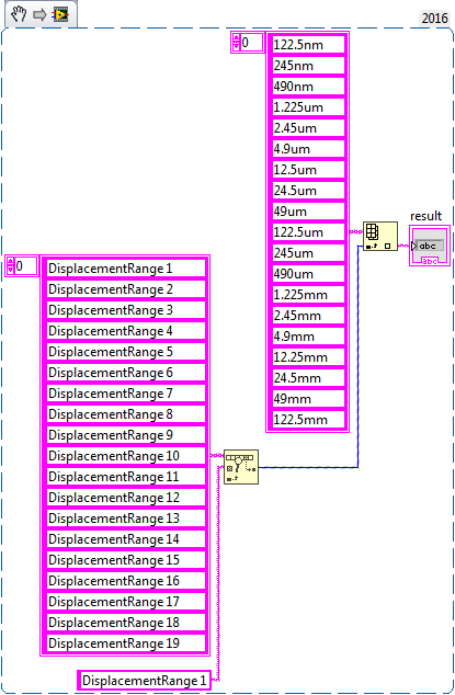
Find and replace the name of the various signals of different value
Dear members
I run a program where I get the output signal ' displacmentrange 1 '...
"displacementrange 19" I need to replace this name with another name
for example
When come signals
displacementrange 1, it should show 122.5nm
displacementrange 1, he must show 245 NM
displacementrange 1, he must show 490 nm
concerning
Benoit zafar
Hello deutchland.
I hope that I have understood correctly, you can use find in table and then use the array index
-
What happens if the analogue output exceeds the range of +-10v?
I use the DAQ usb-6211 of my request card. Sometimes, there will be cases when the analog output would exceed the range + 10 volts. What will happen in this case for a DAQmx? The task just write + 10 volts? Or keep the last value wrote to the analogue of the outpot port? Y at - it hurt by this (giving a value out of range for the AO port)?
If so, what would be the best way to amplify the voltage signal AO of the DAQ card to have a power greater than 10 volts?
Thank you
Lucy
Hi Lucie,.
Looking at the code, I noticed that an error occurs when the data of output voltage exceeds ±10V. The reason why you couldn't see this error now is because you forgot to place a general error at the end of the thread error handler. Without any error VI Manager, you will not be able to display this particular error line errors.
-
Hi all
This should be a pretty simple question, but I can't seem to find the answer online and currently do not have the functionality to test this:
I'm using LabVIEW 8.5 and have a VI that imports data from sensor through the DAQ Assistant. In the configuration tab, there is a range of signal input. What happens if my sensor exceeds this range? I get a warning? The default value is the maximum (or minimum)? I was interested in writing a code to display an error that I approach the limits of this range, but did not know if I also need to include code to display an error if the scope is exceeded as well.
Thanks for the help,
Tristan
Hello, Tristan,.
The behavior depends on the selected range and the device you are using.
If you are using a device with a single input range is valid, we will use this range, even if you set a smaller minimum and maximum in the DAQ Assistant. So, if your device only supports ±10V and you set the range to ±8V, you will still continue to get valid data after your top sensor 8V until what you approach 10V. When you reach the limit of the extent of your device, the output will be 'rail', and simply return the maximum value until the signal is less than the maximum value again.
Note: A device that is nominally ±10V usually has a go-around (such as ±10.2V) which are usually specced in the manual.
However, if you use a device with several ranges of entry then things become more complex.
NOR-DAQmx player will choose the smallest range that entirely covers the interval you choose. For example, suppose that your device supports the following input range: ±0.2V, ±1, ±5V, ±10V and you choose 0V - 3V as the range in the DAQ assistant. The NOR-DAQmx driver will focus on the input range and the list of the entry lines that your hardware supports and choose the smallest encompassing the entire range that you set. This would be the ±5V, because this is the only beach that contains up to 3V. Thus, all between ±5V input signal is returned and none outside this range will be 'rail' to the maximum or minimum value.
We do this because using small beaches make more efficient use of the resolution of the ADC. So, we try to use the most effective range based on what you ask without picking up a range that will make you miss data.
Let me know if I can clarify it more.
-
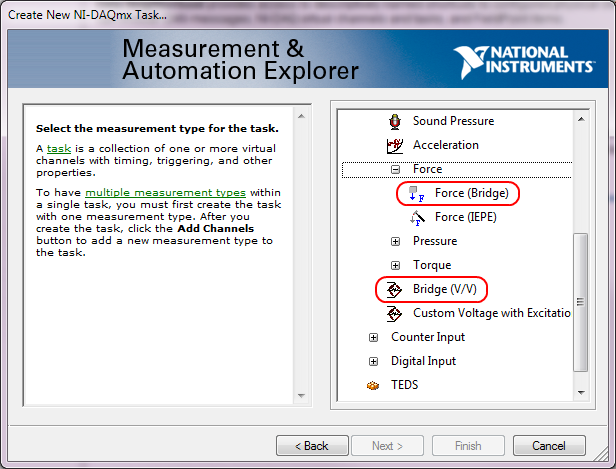
How do I capture the output of voltage full bridge with Signal Express NI9219
Hello. I'm trying to do and calibrate a load cell with the installation of full-bridge strain gage. I use a NI9219 module with a cDAQ chassis. Is it possible to capture the actual output voltage? Signal Express gives me a value of strain, but I really need to know the output voltage. Where to look. I need only two channels for full-bridge. I think that could connect the wires to the two remaining channels and read the output voltage of the strain gauges which would be connected as a tension of the 9219 entry, but I think that Signal Express could give me the voltage and output voltage directly. Any input would be appreciated. Thank you! P.S. I only use this equipment on occasion and am not the more familiar with it, so keep things simple for me. Thanks again.
Hi jgh@AET,
The NI 9219 measures the ratio of voltage full bridge in hardware sensors, allowing any variation of the voltage to cancel. You won't be able to measure the output voltage of the sensor regardless of the voltage without additional channels, but you can measure the ratio of raw tension using the type of Bridge (V/V) . You can also use the type of measure of Force (bridge) measurement of load cell with engineering units (N, lb, kgf, no strain).
This screenshot shows where the two Bridge (V/V) and Force (bridge) can be selected in the DAQ Assistant:
These types of measurement were added sometimes around DAQmx 9.1, so if you have an older version of NOR-DAQmx, your DAQ Assistant maybe not them. The latest version is currently 9.4 of NOR-DAQmx. Front of NOR-DAQmx 9.1, the approach to recommend to measure the load cells was to use the custom with Excitation voltage type and a custom scale. However, Tension Custom excitedly can't Bridge of calibration in the DAQ Assistant.
Brad
-
output signals of the rectangle a PEAK sine wave conversion
Hello
I have a question on the treatment of a PIC16F84 output signals. It seems that the simulation of Multisim does not work properly - but before I blame Multisim, I ask the community NOR or software engineers or a solution. Because I'm German, you are invited to continue this thread in German if it is allowed by the rules of the forum. If you need additional information to analyze my problem, I'll be happy to provide.
The circuit itself has to convert "composition by pulse" signals "tone" (DTMF tones). So you can get old, classic phones work on new devices that do not support the "composition of pulse" more.
The circuit is powered by the analog telephone line current loop line. The PIC is provided by a rudimentary voltage regulation and count pulse signals (voltage failures / power interruption on the telephone line). After that the captain means the series of impulses in their equal number (e.g. 3 pulses = number 3). The captain gives finally two signals with different frequencies to generate a DTMF tone (e.g. number 3 here is 697 and 1477Hz). As you can see in my PDF file attached, it works very well.
Now I have to convert the rectangle wave given by the captain to an at least similar to a sine wave form - otherwise the device that receives the DTMF tones won't understand them.
So I connected a low-pass filter at the output of the PIC. Now, expect the rectangle signal to be smooth in a way as the 'e-function' will (loading / discharging a capacitor through a resistor). But the results are very far from that - as you can see I have very strange curves.
When I implemented a frequency generator with the same output signal as the PEAK and the low pass filter even I get curves as expected.
So we can say that the output of the PIC works like a frequency generator in my circuit. But why does the filter not behave as it should?
I've tried a lot of different values for the parameters of my RC-filter and simulation - this does not solve the problem.
It would be nice if someone has any idea how to solve this problem.
Thank you.
The output impedance of the PEAK may be too high. May be that my car 50 output? Try scaling of impedance of the filter. Do the 10000 ohms resistance and capacitor 10 nF.
Lynn
-
I have a DAQ Assistant configured to read 2 channels at the same time. When I have a graphical indicator of wire to the output, I see 2 signals mixed together. How I divided them into separate signals?
When I wire any type of indicator, it is show that a release of a single channel.
I want 2 indicators showing 2 different signals as expected from 2 channels configured. How to do this?
I tried to use split signal but it end by showing that 1 out of 1 signal two indicators.
Thanks in advance.
Yes you are right. I tried, but I don't have the result.
I just find the path. When we launch the split signal, we should expand it (split signal icon) by top, not the bottom. It took me a while to understand this.
Thank you
-
Hello guys,.
I have a general question regarding the units of packaging such as the USB-9263 analog output signal. If I can use it instead of data acquisition to provide an analog voltage output?
Thank you
ELA
Yes, the 9263 can provide 4 output channels analog voltage (+/-10 v range) with up to 1mA of current drive. Looks like: it refers to the short circuit of conditioning of signals and some protection against overvoltage. Link below is the User Guide:
http://www.NI.com/PDF/manuals/372406b.PDF
-AK2DM
-
[FPGA] Problem with the sinusoidal signal generator
Hello!
At first I want to apologize for my English is not my mother tongue.
Hardware and software I use is:
LabVIEW 8.5
NEITHER RIO 2.4.1
NEITHER cRIO-9014 (controller in time real CompactRIO)
NEITHER cRIO-9104 (chassis and FPGA)
NEITHER 9264 (16 channels, +-10V, 16-bit voltage analogue output Module)
I made a very simple FPGA VI: a while loop, generator of sinusoidal signal and a FPGA of e/s node in the loop. I've specified the Gnerator settings by following the path:
Frequency = 50 Hz
Amplitude = 1
Phase shift = 0.00
Size of the table look-up = 1024
= 16-bit amplitude resolutionFPGA clock frequency (40 MHz)
But the wave of "sine" I got is not what I wanted to get. First of all, its amplitude is 1 V. shouldn't it be coded on 16 bits? If I wanted to get 1V I should have specified Amplitude as a 3277. In addition, 'sine' is not very detailed, it's look like "steps", as many samples vere missing. What I did wrong? I checked the samples and tutorials, I did everything the same way. A I forgot something or not has not specify other parameters?
Thanks a lot for your help!
OK, I solved a problem. It's embarrassing to admit, but maybe this will help someone else
 I blame my inexperience
The main solution to the problem was changing calibration of calibrated RAW Mode. After that, everythoing works as expected. I had a problem with a sample because I was using a multiplier to control the generated sine wave amplitude. But... She was set to 1 in the sinusoidal signal generator. That was the reason for waveform Gradin. Please, don't laugh too much

In any case, thank you for an answer! It is now resolved
-
Cannot use the output VGA on my Satellite A100
I have laptop Satellite A100 and when I use the my monitor VGA output announcement there is NO signal. I checked my monitor and it does not work.
This that I would like to know because there is no my VGA output signal does that also mean that the * S-video * will not not a signal?
I do not have a S-Video > VGA adapter as far trying to save the cost of buying one if it doesn't...
I don't really know what you're doing wrong?
Is your laptop connected with VGA cable or an adapter on your laptop VGA port?When the monitor is connected please use FN + F5 key combination to switch between an LCD display and connected monitor.
It work? -
generate the output waveform on 6259
Hello
I would like to generate signals of "simple" digital square output 3 6259 NI Board of Directors of 80 Hz.
Because of the wiring of my test tool driven 6259 Board, I can't use the output of the meter, but I need to plug into 3 output lines.
I re-used an existing vi and made by a subcontractor, but the generated waveform on my DUT does not have the expected frequencies (although it seems OK on the generated graph). Indeed, there are some forms of square waves, but not continuously. A sort of "pomade" and "elected" frequency does not match the measured frequency. If someone has an idea to help me, I have not experience on labview yet!
Thank you!
You have 4 unique digital States aimed at bike. Each cycle produces 1 full period of each of your square waves. If you want the output to 80 Hz, you must set the sample to run 4 * 80 = 320 Hz clock.
The other thing you see on the scope is that there are short bursts of pulses with parent long time between bursts. The calendar during the bursts are what control tasks. The time between bursts is caused by using the button "run continuously. Also that according to them, you complete vi almost immediately rather than waiting until they run awhile. Put an end to the execution of vi initiates self-cleaning of LabVIEW. These things represent the time brief burst and the ISH between bursts.
-Kevin P
Maybe you are looking for
-
Install Windows 7 on a HP Pavilion G6
Good evening! I recently bought a HP Pavilion G6 comes loaded with Windows 8. I am not happy with the operating system and the desire to change the operating system to Windows 7. I bought a copy of Windows 7 and I put the disc in the cd-rom drive t
-
Impossible to install Common-modules on Portege M300
Hello everyone, I'm Italian and I had some problems with a Portege M300. After the crash of Windows XP, I did a fresh install of XP but, of course, I lost all drivers. I tried to install, but I can't do that because it doesn't have the Toshiba common
-
I am trying to install 2 new computers running Windows 7 on one network of 12 others who are running Windows XP, do all need to have the same operating system? I have a printer connected to the computer and cannot access it from my other computers.
-
My HP pavilion DV7 1245 x with Vista has stopped recognizing the CD.
When I put a DVD/CD player and click on the disc or the player open, it is said, please insert the disc in the drive. When I put a CD inside whirs for a little while but when I put a DVD in nothing happens at all. When I ran FixIt it says fair-medi
-
Verbatim Store ' Don't Go external hard drive - unable to connect to
Help I can't connect to my Verbatim Store ' Don't Go Hard Drive - USB 3.0 - 1 TB external hard drive. I run Windows 7. In computeradministration he appears white and tells 'Help' me, I have to initialize it. But when I try, I get the message (in Dani