FPGA device
I use a PCI-7833R FPGA, I know that it uses an FPGA virtex II FPGA, but I want to know the exact FPGA device used. See the attached table. Where can I find this information? I want to use the same thing with a 9148 with a Spartan II as well. Thank you!
Right-click on the target FPGA in your project, and then select Properties. In the General category, there is a field called target information. This is what it says for the PCI-7833R:
Target class: PCI-7833R
FPGA device information:
Family: Virtex-II
Type: xc2v3000
Speed level:-4
Package: fg676
Jim
Tags: NI Software
Similar Questions
-
Could not find the FPGA devices in Labview 20104 32bits
Hi, I just installed Labview 2014 32 bit on my computer which also has 32-bit Labview 2012.
The FPGA card is PCIe-7842R and the operating system is Windows 7 64 bit.
The FPGA card works well on the 2012 LabVIEW. But in 2014, there not the target element and the device that is used to add the FPGA hardware.
Need to install something else?
Thank you
You have the LabVIEW FPGA for LV2014 and installed the drivers OR-RIO (supported by LabVIEW 2014 development)? (Look in MAX under software)
-
Lab view fpga: device driver for virtex 5
Hello
in 2010 I worked on labview fpga and spartan 3
now, I want to buy a virtex5 xilinix company but I need to know is their a device driver for this kit in labview 2011 or 2012!
Best regards
m, s
Hello mangood,.
Currently, the only target FPGA that is supported by LabVIEW FPGA, other than our FPGA cards in our product page, is the Xilinx SPARTAN-3E XUP Starter Kit.
-
FPGA device configuration, package and speed grade.
Hello.
Where can I find the news of grade package and the speed of the FPGA inside of the PXI-7842R? I ask because I want to build a project XPS in the Xilinx XPS and program needs this info.
I followed the example in the "how to use designs based on Xilinx Microblaze with NI LabVIEW FPGA 2009 and the R-series modules". There, he gives the info for the specific FPGA (PXI-7852R and PXI-7953R) they use. It's a Virtex5, ff676, xc5vlx50, level-1 speed, but the authors do not mention where one can find this info.
Thank you
Bill.
Nevermind, found the info in this way:
Instruments\LabVIEW national 2010\Targets\NI\FPGA\RIO\R Series\Pxi-7842r
Bill.
-
Software FPGA with LabVIEW 2013
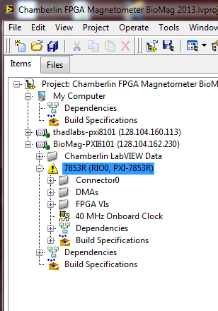
I have a system with a rotating computer "development" under Windows 7 and an NI PXI-1036 chassis with a PXI-8101 controller as well as a card FPGA PXI-7853R. Recently, I upgraded to LabVIEW 2011-2013 of LabVIEW. I kept LabVIEW 2011 installed just to make sure everything is still working on the new LabVIEW.
Now, when I open my project in LabVIEW 2013 Project Explorer, my FPGA comes with a warning triangle yellow next to him (see attached photo). The warning says:
"Software support for this target FPGA is not installed on the computer. You can view and copy elements into the project, but you can not compile any screw under the FPGA target, until you install support for the target. Refer to the documentation of specific material for more information on the proper drivers and for more information about the installation and configuration of the target FPGA ".
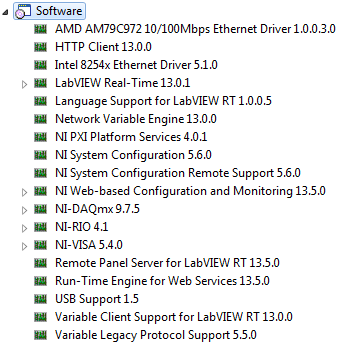
Regarding the installed software, I have LabVIEW SP1 of 2013, 2013 of LabVIEW FPGA Module SP1, SP1 of Module 2013 LabVIEW Real-time, and Xilinx Compilation tools 14.4. On the chassis of the TARGET (with the PXI-8101 controller), I have attached a list of installed software.
Interestingly, when I open the project in LabView 2011, no errors or warnings are present with the FPGA card. It is only under LabVIEW 2013 I see the warning. Did anyone see a glaring omission of software that could be the cause of LabVIEW raise this error? Thank you for your help.
Best guess is that're missing you the driver for your FPGA device. Try to install the latest version of NOR-RIO (or at least the version supplied on your 2013 SP1 install disks). Have you installed device drivers at the time that you have installed SP1 2013 LabVIEW?
-
[FPGA] Associate existing target FPGA with real hardware?
I started to write the code to FPGA and to support this, I have created a 'new' device FPGA - i.e. a device in the project but not associated with any actual hardware.
Now, a colleague has access to some real hardware and tries to run the code on this subject, but has resorted to the creation of another target FPGA from the existing FPGA device (real hardware) and copy of the hierarchy of the code of the other device 'virtual' on him. It is also having to copy/recreate elements such as FIFOs in the project hierarchy.
Is there an easier way to simply link the target that we created in the first place with the actual hardware?
Sorry, I thought that the question should pass a target FPGA to a project to another (existing) without having to recreate the FIFOs, clocks, and other resources.
If your FPGA card lies in a real-time controller you can simply change the IP address of the system in real time (as from real IP of 0.0.0.0 or any other intellectual property on the real-time controller) to run on a particular system.
-
volatility of FPGA data persistence
I'm just wondering on volatility persistence different methods of memory after power to LabVIEW FPGA devices? Is it possible to make sure the data persists after the electric bicycle?
There is no that many techniques of memorization. You can store data on the FPGA, doors logical, or in RAM. These two are volatile - they lose their content when it is turned off. Some FPGA cards have on board FLASH not volatile, but which is generally used to store a bitfile to load at startup. I don't know if it is possible that the FPGA to access the FLASH during the race, but if you must write custom code to low-level (non-LabVIEW) to do, because there is no built-in functions that would allow.
-
LV FPGA workflow nested CLIP w / NI SMU-6591R
Hello
I develop an application on a NI-SMU-6591R Board. My installation also includes a SMU-1085 w chassis / controller 8135.
Goal: set up a VHDL project prior to the Commission of 6591R. Given that the application requires access to 2 ports Mini SAS HD and the VHDCI connector on the front of the 6591R (physical front) a CLIP nested is the only option here, isn't it?
I am quite new to the LV FPGA framework. In order to understand the flow of the whole project, I would like to launch a trivial VHDL design on the 6591R: a D-FlipFlop edge triggered w / Syncronous reset. I have attached the the D - FF and the wrapper of CLIP VHDL code.
I would like that (1) a little (LV::boolean/VHDL::std_logic) to pass the port D of the D - FF VI (name FDF/D) and (2) drive the LEDs of the Board of Directors according to the signals of outputs (FDF/Q and FDF/QB). Also, I want to read (3) the same outputs (FDF/Q and FDF/QB) back to the VI flying two Boolean flags.
Following the white paper OR, I have:
- Managed to create a XML interface of the import VIDEO Wizard, import the 2 files VHDL (D - FF and its packaging).
- Selected the ELEMENT created in the IP-level component properties window. The LV_DATA_IN (host2fpga) and LV_DATA_OUT (fpga2host) I/O appear in the project tree, under the CLIP icon.
- Created a new VI under the FPGA device with an infinite while loop. Inside the loop, I dropped the LV_DATA_IN and the LV_DATA_OUT e/s and connected with a control (to LV_DATA_IN) and two indicators (of LV_DATA_OUT).
First of all, why in a simulated execution mode, the behavior of the indicators is totally random? They are not connected to one of the connectors 6591R...
Linking the FPGA VI, he reacts to any change in the control LV_DATA_IN button... Why?
The design works as expected in Vivado both in behavioral simulations and post-synthese.
Before asking here, I tried to understand it on my own. I have read all the documentation that I found on campus (I got access to LV Core1, Core2, Core3 and FPGA course material) and on the internet.
What is still missing me?
TY for your kind help!
-
Try to find a file complete configuration of the user (UCF) or a diagram showing mapping chip Spartan pinout for card FPGA devices and I/o.
Yours,
Now that is COOL BEANS... new we can use...
Do apprecaite the relevant details and we will work in the future. Acually, was to make an inventory of the party today in preparation for class with a student helping and he found a few tubes of the old chips 555 timer, asked what they were for and we had a good dialogue on the function and the importance of calendar clock in computers, and how to get developed the waveforms and such.
So I can see set clock calendar as a real overview of the digital electronic transactions, especially being able to slow things down enough to capture the action and study it better.
Very well.
Chris Speck
-
Export the list of the names of orders of FPGA in plain text?
I'm working on a Labview 2014 project that uses a compactRIO with architecting FPGA device. When I open the Strict 'FPGA - Def Type Reference.ctl' file on Real_Time.lvproj and right-click on "FPGA Refnum" and then select "configure FPGA VI reference...". "I see a list of orders with the name and the type of description (Boolean, U32, I16, Fixed Point etc.) There are a number of them, about 200 in total, and they do not fit on one screen, I have to scroll a bit small provided not resizable window, and I can't select and copy the names as if they were plain text.
Is there a way to export this list of control names and types in a file in plain text, for purposes of documentation and external reference? Or such a created file "behind the scenes" somewhere during the FPGA compilation step, that I can find?
In case someone else wants to do that, I used the unix tool "xmlstarlet" XML (also available for cygwin) to get the names and the widths of all the bits bitfile FPGA registers. This gives you two text files, but the order is preserved if you can copy and paste separate columns in Excel and if you (name, bitwidth) aligned pairs.
xmlstarlet salt t m ' / Bitfile/VI/RegisterList/Register/Name / text () "-c. n FPGA/bitfiles/FPGA.lvbitx > RegisterList.txt
xmlstarlet salt t m ' / Bitfile/VI/RegisterList/Register/SizeInBits / text () "-c. n FPGA/bitfiles/FPGA.lvbitx > SizeList.txt
-
CPU register accessible in LabView FPGA FlexRIO
Hello people, I wonder if it is possible to get the following behaviors of Labview. I think that it is not.
Description of the system: application of CVI which communicates with SMU FlexRIO via controls and indicators.
Problem: The design of a CPU-FPGA interface specification which lists the "books" as a combination of reading and reading/writing-the bit fields.
Example:
According to the specification, there should be a 32-bit register. 31: 16 bits are read-only, and 15:0 bits are read/write, from the perspective of the CPU. In the world of labview, I would just do a uint16 control and indicator of uint16 and do with it.
However, to meet the specification (written for microprocessor buses) traditional, a reading of 32 bits of an address should read back the full content of the 32-bitregister to this place (implemented as flops on the FPGA, with appropriate memory within the FPGA device mapping). In the same way a 32 bits of an address entry must store the values in this registry (properly masking wrote at 31: 16 bits within the FPGA device).
Is it possible for me to have a unique address (basically, a component unique labview block diagram) that will allow me to accomplish this behavior? It seems to me that the only solution is to pack my records with bit fields that are all read, or all the read-write in order to register in the paradigm of labview. This means that the spec should go back and be re-written and approved again.
Thanks in advance,
-J
Thanks for the detailed explanation. I am familiar with the reading and writing in the FPGA registers - I did a lot of work non-LabVIEW recently with an Altera FPGA. I haven't, however, used the CVI to LabVIEW FPGA interface, I only used the LabVIEW interface. I'm not sure if your question is about the CVI, LabVIEW FPGA interface or both.
JJMontante wrote:
Thus, a restatement of my original question: y at - it a mechanism with the use of indicators of controls where both the FPGA AND the CPU can write to the same series of flip-flops in the FPGA? If I use an indicator, the FPGA can write to the indicator, but the CPU cannot. If I use a control, the CPU can write in the control, but can't the FPGA. Is this correct?
On LabVIEW FPGA, a control and indicator are essentially identical. You can write a check, or read a battery / battery, using a local variable in the FPGA code. It is common to use a single piece of front panel to transfer the data in either sense, and it's okay if it's a command or an indicator. For example, a common strategy uses a Boolean façade element for handshake. The CPU writes a value to a numeric control, and then sets the value Boolean true to indicate that the new data is available. FPGA reads this numerical value, and then sets the Boolean false, which indicates the processor that the value has been read. The LabVIEW FPGA interface (side CPU) covers also all elements of frontage on the same FPGA whether orders or the lights--they can be as well read and written.
That answer your question at all?
-
FPGA error: failed to create the C Series module
I use sbRIO 9631 with LabVIEW 2012, as well as the FPGA 2012 module. Everything worked fine until yesterday, I got this error when creating a new FPGA project.
«LabVIEW FPGA: an error has occurred loading the VI on the FPGA device.» Check that the target is connected and powered and that the target resource is configured correctly.After ignoring this error, I can create any VI in the FPGA target, compile it and it works but can not do anything with host one. MAX configurations show so no error.
I have attached snapshots for convenience.Note: This sbRIO came with a DVD of LabVIEW 8.6 and similarly associated modules version. I had been using this version for a year. Then I got LabVIEW 2012 with the last modules and now facing this error.
Hi NapDynamite,
You should not need to uninstall your previous version of LabVIEW for the development of your PC.
You can see what version of NOR-RIO you have installed on your sbRIO? You can view it by selecting the sbRIO under "Remote Systems" of MAX, and then by selecting the category of software. You may need to update the version of NOR-RIO that is installed on the sbRIO.
You can try this first?
Kind regards
-
Still missing FlexRIO 15.1.1 installed drivers
Hello
Freezes Windows to log in. reduce it to charger OR. Do you have all Windows update and update OR. Still does not solve the problem. Decided to uninstall the software OR. 15.1.1 FlexRIO made the updates installed. Now missing a couple of the pilot. Help, please.
NOR-SMU-7961R
NOR-RIO-FPGA devices appear in Device Manager
AE 4 missing drivers here:
PCI\VEN_1093 & DEV_C4C4 & SUBSYS_742A1093 & REV_00
PCI\VEN_1093 & DEV_C4C4 & SUBSYS_742A1093 & REV_00
PCI\VEN_1093 & DEV_C4C4 & SUBSYS_742A1093 & REV_00
PCI\VEN_1093 & DEV_C4C4 & SUBSYS_742A1093 & REV_00
Thank you
hms168
The reason why it keep the gel is the DAQ card was bad.
-
Increase the rate of target on Veristand
Hello
I am a novice user of Veristand. I'm doing a feedback from control with the help of a compactRIO:
RT OR cRIO-9024
Chassis cRIO-9113
9220 and 9263 modules.
I use Veristand with a compiled since Simulink model to make my will.
I want to be able to reach frequencies of 10 KHz loop or more, but the loop of the target rate freezes the system when I try to go beyond 700 Hz.
Is it possible to do?
My model is very simple, for now, I'm simply connect the 9220 1 entry at the exit of the 9263.
Thank you in advance,
Kind regards
Rates
Hi prices.
The 9024 is unable to run NI VeriStand at your desired pace. As you can see, it tops out around 700 Hz. There are several reasons for this, but the end result is that you will need different hardware to run at your desired pace. A 9082 will be much faster, and a SMU-8135 will be even faster than that. Also if you use PXI, if you only need of IO and no treatment only Co, our PXI DAQ devices allow you to hit the NIVS rates much faster than the PXI FPGA devices.
Good luck!
-
Custom development of modules CompactRIO - Embedded window of "missing" project manager
Hello!
The scenario:
I am currently working on a custom CompactRIO Module. The material is made for the most part, I installed CompactRIO MDK 1.0 and I want to configure my CompactRIO system and develop the driver VI for my module.
The steps required to configure the cRIO system before you start developing the pilot VI is the following (as mentioned in the documentation of MDK):
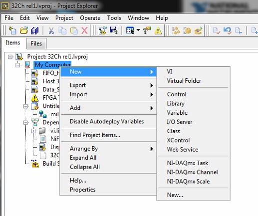
1. launch LabView and select as an execution target FPGA devices. The Embedded project manager window will appear.
2. Select the file-> New and create a project (LEP) LabView Embedded file.
3. ...
Used equipment:
-LabView 2011, a Student Edition license
-LabView FPGA and real-time modules
-NIRIO 4.0
OR-CRIO9024 controller with 8-slot chassis
The problem:
After the launch of LabView and selecting FPGA as a target (see figure), even by pressing the "Go" button next to the slide in the menu window of Embedded project manager will not appear.
I also tried searching in other menus, without success.
Issues related to the:
1. where can I find the Embedded project manager?
2 is it possible, that I can't find the window of Embedded project manager because I have a student licensed LabView?
3. How can I create a LEP file in this case?
4. can I use (and if so, how?) the option "create a pilot instrument? (see the attached figure)
Waiting for answers,
Levi
Hello!
After some research, I managed to create the link between my custom cRIO module and LabView.
The complete solution (with LabView 2011):
-Add the line "cRIO_FavoriteBrand = generic ' in the file LabView.INI"
-Launch LabView
-creation of a vacuum of the project and select FPGA execution target, click OK
-Select 'CompactRIO Reconfigurable Embedded System' as the project type, click Next
-the next step is the detection of the chassis / modules, followed by the creation of the new FPGA project
-Add the custom module: click right on the target FPGA-> New-> C Series-> new target Modules or peripheral-> series C Module-> OK
-Enter the name, select 'generic' module type, enter the location
Hope it helps someone someday.

Levi
Maybe you are looking for
-
Notifications do not close automatically
I turn to a Mac after more than 30 years with a PC. I now have problems with notifications. They do not close until I click on 'Close' or 'reply '. I tried to use the command defaults write com.apple.notificationcenterui bannerTime terminal 5 but t
-
What software and features settings I lose when reset PC factory restore?
I intend to restore my laptop HP-G60-647NR to 'Factory or as bought Specs' but I forgot what was in or on the start menu, so need to know what I lose? Thanks, cricket
-
I'm running vista I have a xp CD. I want to install xp on an external hard drive. I changed the bios boot order and booted up but vista boots all the time. (I have the bios phoinex). I run the cd via the Explorer of windows vista and the installation
-
AOL error 0 x 84008001 AC-0000
Not sure that if this is the right place but I saw a question already posted on this site, the answer did not help me if. It's on AOL Desktop 9.7. I use a "Home Network" via the connection options for AOL, but whenever I try to connect to it on my de
-
I use a USB sound card with a CMedia CM119 chip inside, for whom the 'Generic USB audio' drivers are called automatically. According to the data sheet of the chip, the microphone input has a + 20dB boost that can be turned on and off, then another am