general switch in labview
Hi all
I can't find the switch of executive functions in LabView. I looked under the two function > measure e/s and function > e/s Instrument with no luck. I also tried opening the examples of Executive of switch, but it is said that 'this example requires a kit add-on to run. The necessary Toolbox is not installed. »
I am very sure that I installed Switch Executive. Can I use it to the MAX and I can also use it in TestStand.
LabView 8.6
Switch Executive 3.0
Try the tips from Sandra T.
post if still problem persists.
Tags: NI Software
Similar Questions
-
A (brand/break) switch in labview programming
Hello
I'm trying to replicate a physical switch in labview. This switch is dependent on the pressure. I.e., when the pressure reaches a certain threshold, the circuit of the switch is made, and when the pressure drops to a certain limit, the circuit is broken. The pressure is measured with a transducer with output voltage. In addition, the switch has an output voltage too.
The way I'm trying to represent it is programmatically specified below,
When the pressure is tilted up to the limit of some, the switch circuit is complete (en) and a green light on the control panel. And when the pressure is tilted up to a certain limit, the circuit of the switch is broken, and the green light turns off.
One way I can maybe do this by the presence of two assistants to acquisition of data, one pressure reading and the other voltage reading; have data output through a case structure and have the luminous glow when the circuit is realized. - AND, at the same time, the pressure on the other display assistant DAQ at this stage. If it is the 'simple' and 'good' how to do it, that I must have some connection (relationship) between both the DAQ asisstants so that the value of the pressure at this time of 'full circuit' is displayed (?) or can I run independently and still achieve?
Can anyone share their thoughts on this program?
Thank you
RP.
Working from the example of .vi sample report (Word), we have been able to implement the block diagram below.
Looks like there are some other aspects of your project to be considered, RP. For any other questions, we will continue to work on our open service request.
-
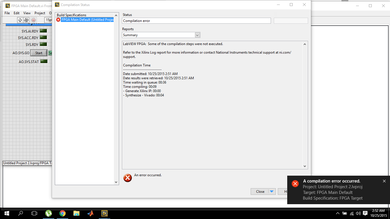
LabVIEW FPGA, 2015 compilation error
I've recently switched to LabVIEW 2015 and I'm working on OR myRIO. So also installed myRIO 2015 bundled software. The problem I have is that the compilation of fpga fails within 10 seconds.
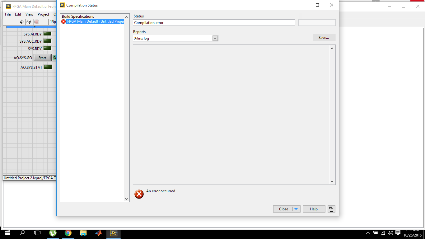
and the target Xilinx journal report is empty
The first time when I tried to compile on 2015 version, it failed and the message box that failed came alongwith the avast antivirus warning for malicious activity. I reported it as wrong and now I tried several times with avast shield disabled control, but the results are the same. While the version of labVIEW 2014 works very well.
Now, I'm sure that there is something wrong with the installation of Vivado because this dll is part of it. The dll must be default in the2014_4\lib\win32.o directory C:\NIFPGA\programs\Vivado if you are using an operating system for 32-bit AND also in C:\NIFPGA\programs\Vivado2014_4\lib\win64.o If you use a 64-bit operating system. If the dll is not here, it is probably that the anti virus (I've never seen what happens to Xilinx but I have for other stuff).
I'm emphasizing the 2014_4 because LabVIEW 2015 uses Vivado 2014_4 while 2014 LabVIEW uses Vivado 2013_4. Since you have also installed LabVIEW 2014, you must have 2013_4 as well and if it works, you will find the dll I just wanted you make sure you check the correct directory for the Vivado 2014_4.
Download and install (reinstall or repair if already installed) 2015 LabVIEW FPGA Module Xilinx tools Vivado 2014.4. You can also use the DVD Setup if you have. It would be a good idea to do the installation with the disabled and even anti-virus try the first compilation the same. Try and let me know if the problem persists.
Kind regards
-
How can I optimize control of some switches through the use of the card NI 6218 and labview? Can I use the digital I/o and how? Is this the right way that I make a virtual switch in labview and connect them with the OR digital CHANNEL. Then the real switches are connected with the corresponding digital OUTPUT channel OR? Thanks: smiley
Here are some ways to make a basic digital output. Alos look in the examples of the expedition (help > find examples) and give a glance to the DAQmx to start.

-
2013 LabVIEW allows the user to return to the LabVIEW 2012 or 2011?
Hi all
I have LabVIEW 2013. I noticed that in LabVIEW measurement and Automation Explorer (MAX) under the LabVIEW Run-Time 2012 SP1 f2 software is listed. This somehow means I can return or switch between LabVIEW 2013 and 2012 without having to install/reinstall?
The reason why I ask, is that I have several instrument drivers written for LabVIEW 2012 sp1 I want to use.
This is probably a silly question, I know.
On a related note, is it possible to tell if a driver written for an older version of LabVIEW will work in a new version of LabVIEW? Or you just have to play with the software?
Thank you
Oh, John
Hi John,.
More explicitly answer your main question - you can install multiple versions of LabVIEW in parallel (at the same time, on the same PC), however that one version of patch of each major version (for example, 2011, 2012, 2013) can be installed - you can not install 2012 and 2012 SP1 at the same time.
The runtime that you noticed has probably been installed with another component that was built in this environment.
As Dennis said, the big thing to keep in mind is that your screws will have to be upconvertis/resized when moving between versions.
If your instrument driver is written in 2012 LabVIEW using the serial at low altitude of LabVIEW drivers, it will certainly work in 2013. If you open the screw driver in 2013 and that you do not see workload issues, you should be good to go. If pilots request DLL or another have external dependencies can be involved more work.
Kind regards
-
Several switches inside the a test sequence
Hi all
I'm doing a few stages of switching in a single Multiple digital limit test, so what I did is incorporated all the controls switch in labview. Unfortunately, I got an error when he got to the step with the switching (an error occurred when trying to access device PXI1Slot6
Another process has already logged to this switch module.).Is it possible to disconnect the teststand switch so that the labview vi can be used without interruption, or y at - it another way to do switching multimode in teststand I don't know?
Thank you for taking the time to read.
One more thing...
You can use the adapter of the sequence with a step of the multi-digital. Then create a sequence that will have several stages.
I illustrate this in the sequence file attached.
Let me know if you have any questions.
-
Formula node - text do not cover wrap in LabVIEW 2011
I recently updated a usage control system general vi from LabVIEW LabVIEW 2011 8.0. In the previous version, the text of the node form (real expressions) encapsulated automatically reaching the edge of the box. It does not in LabVIEW 2011.
Although I can turn on the scroll bars, my boss would prefer to see the text on several lines, as before.
Is it possible to force wrapping?
Otherwise, carriage returns can enter arbitrarily without affecting the analysis of expressions?
Shift + enter will put you on a new line just as if line took place.
As far as just using the Enter key and if it effects a formula, why not give it a try? I don't think that CR can be placed.
-
VI Analyzer - edit saved config with LabVIEW 8.6.1 problem
I use VI Analyzer with great success, but have recently switched to LabVIEW 8.6.1. I am trying to load, edit and save a file previously configured and when I save and run a file CFG 'old', the tests are completely different.
Specifically, I'm trying to change the chess ' maximum reported "since 'Block-> Style-> son under objects' from the default setting of 5 to 10. After I change the value to 10 and save the configuration, change the selected tests stored in the CFG file and I can not run the same tests selected before changing the numeric value.
I have attached my 8.6 and 8.6.1 CFG files
I wonder if this has something to do with this serious bug.
I think I found my problem. We have recently added the LabVIEW Instrument Driver VI Analyzer plugin to our installation of LabVIEW. I created the cfg files until we added it. I use the VI Analyzer API to load and run tests on a selected VI.
When I insert my old CFG file via "tools-> VI Analyzer-> Analyze live... "on a computer to which I added the plug driver, the default behavior seems to be adding newly found as selected tests (checkbox = True). I changed a value ("Block-> Style-> son and objects-> maximum failures reported" and then by saving the CFG file, and then running the CFG file via the API.)
I saw 22 more tests running that I select and thought that my change of the numerical value may have had something to do with the bug that I quoted above. I know what the problem is now. I just need to deselect the Instrument Driver Tests when I save the CFG of the user interface.
I would say when you load an existing CFG with the VI Analyzer, the default behavior for newly found tests should not be included (box = False), or that a dialog box should inform the user that new or previously configured tests (presumably of the plugins) have been found or are detected as missing.
-
In order to control the number of cells in a column chart, I need a control switch that can choose between the numbers for example. 2048, 1024, 64, 128 and 256, 512. Is there a switch of LabView or vi for this action?
Emmanuel says:
Jeff· Þ· Bohrer says:
APOK, this is exactly why we use controls to ring like that of my last post
 there is no need for all these tables of choice.
I did just 'rube d' new?

No, as you will get Rube had, just go to school. Forum participation is often a source of learning for all of us. Keep wallahs what you know!
-
custom control represent switch
I'm trying to represent a switch in LabVIEW using a dial. However, I can't understand how to customize my control to watch as I want. I would like him to have options as below
/
_
\
So I inverted the numbers on my dial so the needle goes counterclockwise. Then I got rid of all the "decorations", so apparently not 3d, flat. But, if I put the maximum of 3 he puts the three around the position of o'lock 7 by default. I want essentially the three to the 01:00 position. So, my next step was to do the maximum, go up to 10 and hide the numbers past three. But, if I do this, the user still has the ability to adjust the past 3. How to make this work?
Thank you.
Apparently I need two characters to be displayed.
-
Hello
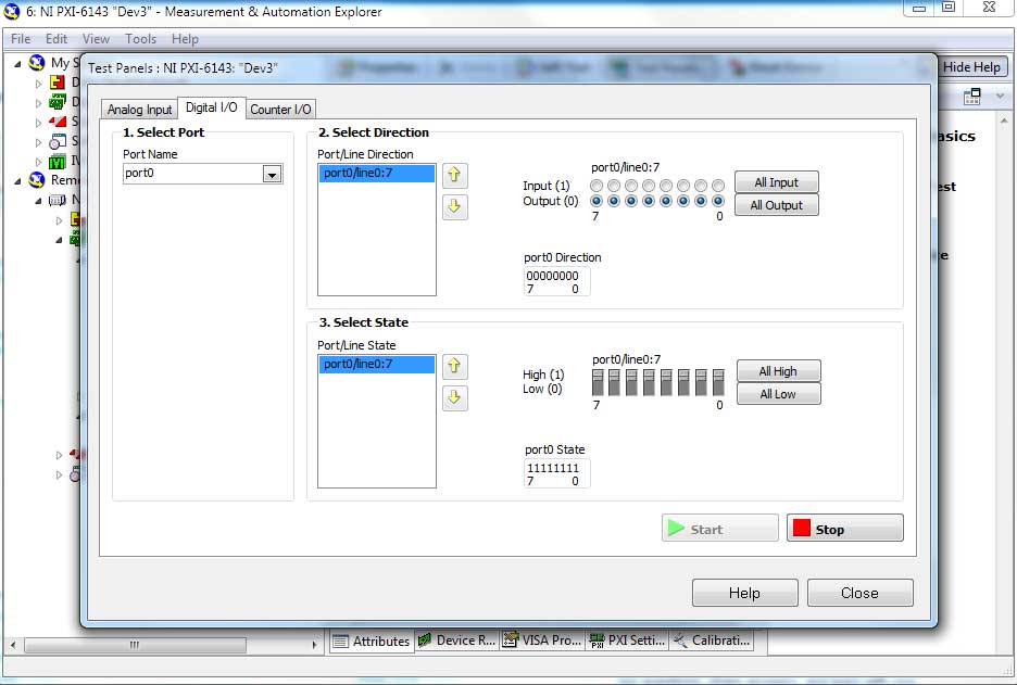
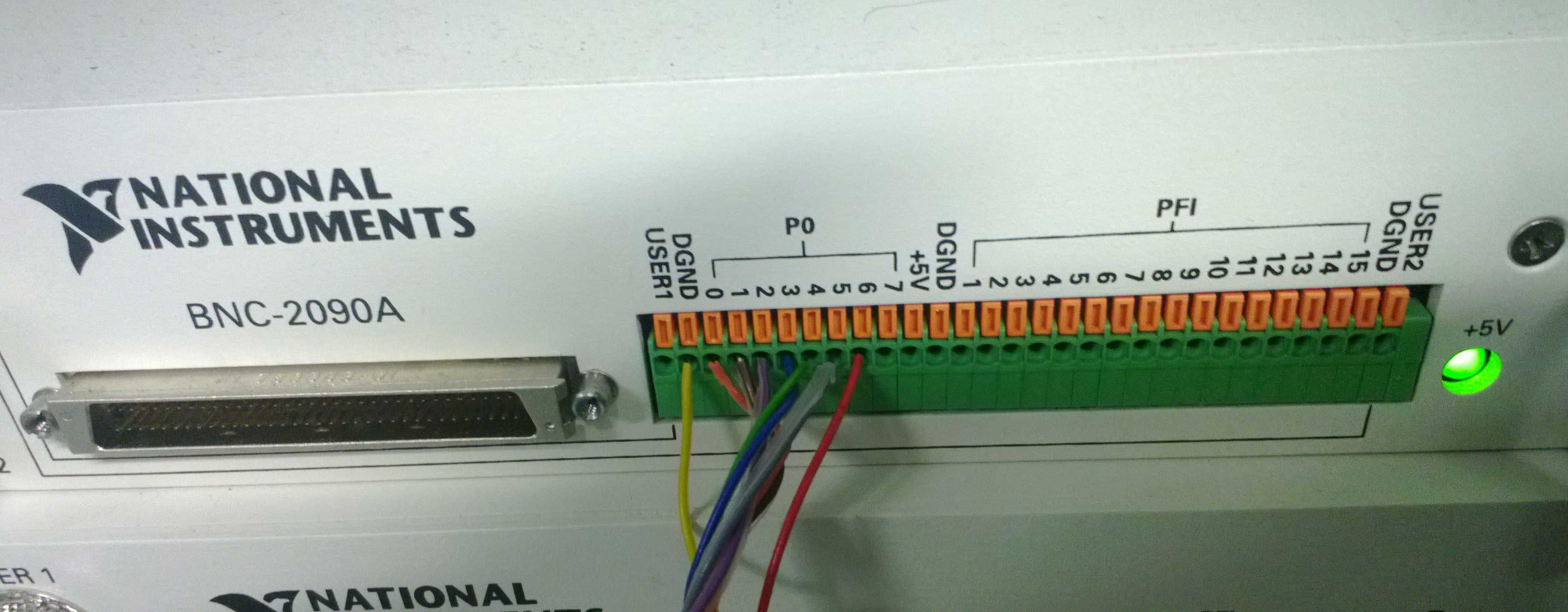
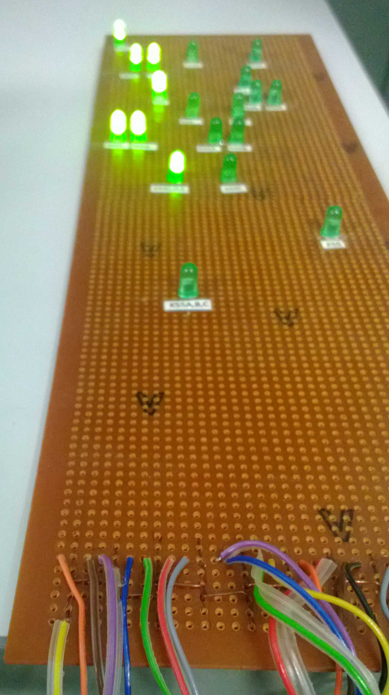
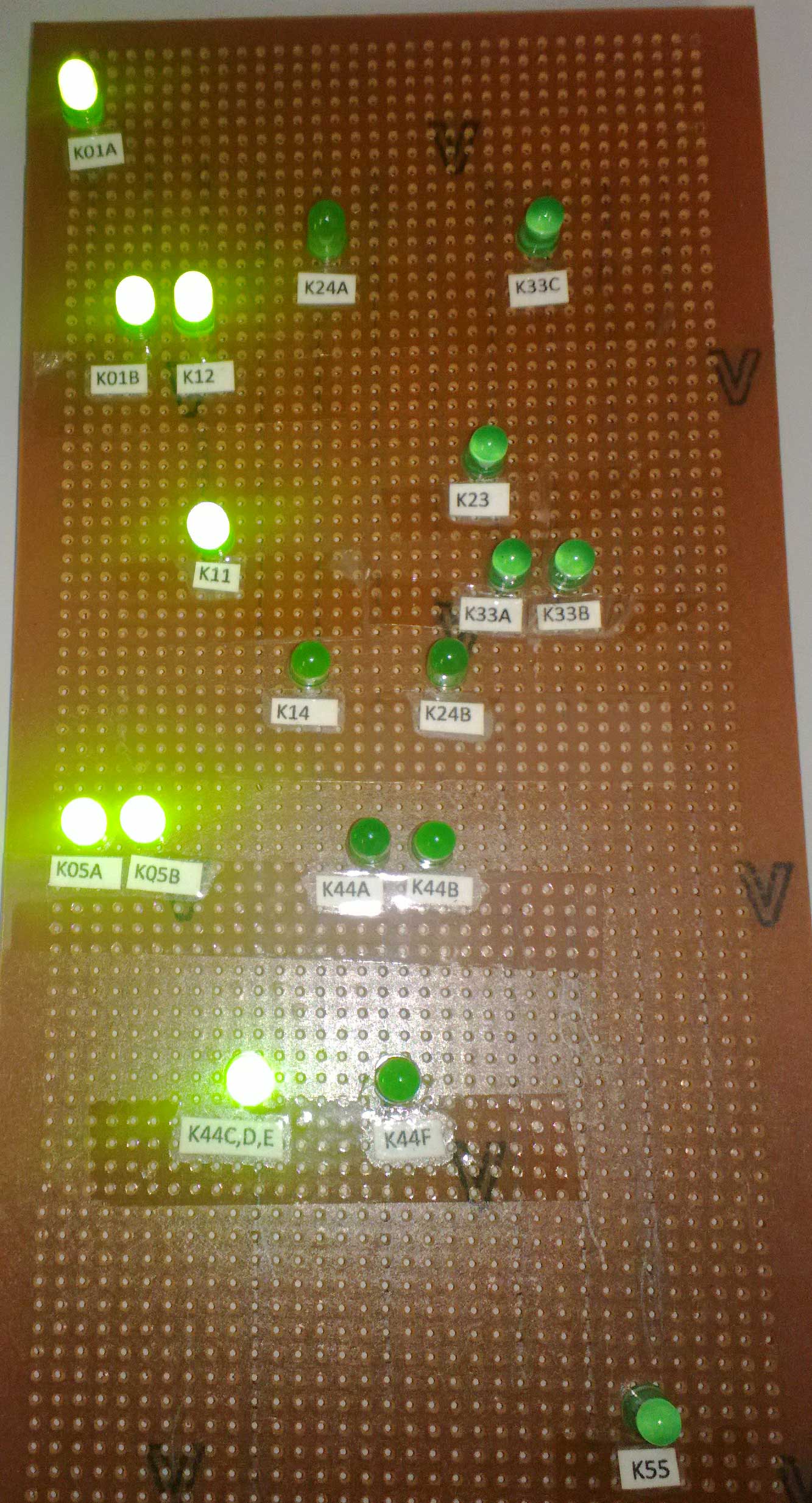
I have some LEDs on a vero Board that are connected in the connector mounting rack BNC-2090. The rack mount is connected to a PXI-6143 DAQ card where I use 8-bit DIO to turn the power button lights. Everything is connected and works when installing high up on the digital output.
How to turn the LED power switch interface LabVIEW? I also want to put the logic, but I'm sure I can do it myself.
See you soon.
Hello Terreh,
Please post on the forums OR! If you create a LabVIEW project and right-click in the project > New > targets and devices, you can add PXI target for the project. It will be published to the same level, as workstation category. Create a VI under the target and then drop a DAQ Assistant in the block diagram. Now you should be able to see the supported devices.
Best regards
Alina M
-
Hello. Just a quick question: business structures flexible while constantly questioned by one while loop? For my experience, I need the system to start in a configuration, turn off by pressing a button and from there the off State have a button that triggers another sequence once. I've tried to achieve by constantly questioning a case structure with a while loop, but when I run my program the signal appears as if it is locked into the State at startup time (I tried with start, stop start and secondary test and both secondary boot off the power). I suspect that I might have to release some kind of memory when you press a button, but I am not sure how I should approach this or anything that I have to use screws. The fact that my codes within the structure of the case so that loops (I'm production of pulses) may also have something to do with it.
If you have any other suggestions, I'd be happy to hear. My goal is to make this program can switch to all States, that I need using only two buttons as soon as it runs. I can do more complicated for me, but it seems it would be the easiest way after watching the tutorials.
I have attached the VI if someone wants to look at precisely what I did. It's a little complicated, but simply ignore all that are not, all in curls or structures of the case. As I said earlier, the question is not choosing between the States, he is switching between them while the program is running. I'm under Labview 2009 SP1.
I was finally able to open your VI. It takes FOREVER to load. There are so many things wrong with your code, it's hard to know where to start. First, as suggested you use subVIs. In addition, the general rule in LabVIEW programming is your VI should fit on a single screen. It is very difficult to keep track of what is past or see how things fit together when you have to scroll the schema-block in all directions. A major problem that jumps out is the nesting level, you have with loops in loops with loops. You realize that ALL code must complete its execution in a loop before it can move forward to the next iteration. You have six parallel loops nested within another lop. Each of these internal loops is set to finish before a front panel control. So, in order to perform an iteration of the loop e euser must press stop six buttons. To make matters worse, you have different stop as the case buttons, you are in.
The best advice I can give you is to throw this code and start over.
-
Keyboard acting strange on Tecra A2
Hey,.
Keyboard is really strange on my Tecra A2. Him answer one key held for a long time, then react quickly with 2/3/4 of the same letters. I think it may have something to do with the function key as the F10 touchpad light icon still flashes, also when I type space, generally, switches between normal and large screen.
In the Device Manager, all right.
For any help or suggestion would be greatly appreciated. I'm going insane using the screen keyboard!p.s My knowledge of computers is poor
Hello
Hmmm, the F10 keyboard light can be turned off with the function FN + F10.
This feature allows small grey arrows on the buttons like U, O, or K.
I think that it is also the reason for switching between normal and wide mode using the space key.
The FN + space will allow this function.The repetition of characters can be changed in the keyboard option in the control panel. I recommend to play a bit with this function.
-
connection of an external matrix lines
Hello
I have 2 boards of matrix I want to connect all the lines upward on the external connector.
I use and test bench to create a test sequence you want router programmatically a stem of the instrument on a spit of had TO based on the names of the pins.
I put in place general switch with the names on the matrix.
Do I need to use routing groups? or can I just have a function to the test that says something in the sense of 'connect? ' PSU + v to DUTVdd
I don't really want to hardcode the routing groups, even if they are editable within the Executive branch of the switch.
Jacob,
The default property of 'Activation' from one stage of TestStand works by linking routegroups and routes pre-configured. What you can do to overcome this limitation is the following:
Max:
- On the tab ' Report/bus', create a Bus from r0 to Dev1 and ending the rX of Dev1. Add Dev2 r0 to Dev 2 rX. This creates an electrician between r0 on Dev 1 and r0 on 2 Dev throughout rX.
- Go to the tab "Channels/Exclusions", the value r0 rX Dev1, Dev2 as "reserved for routing.
- Give all column names.
In TestStand:
- Create three [RouteSpec, channel 1 and canal2] string variables and variable number [status]
- Somewhere in your code are a step in the 'statement' assign names to channel to channel 1 and canal2
- Drop an IVI > switch step
- Click on «Change the switch...» »
- Click the 'Switch Executive' radio button
- Select your 'virtual device name.
- Select the operation as being 'get information '.
- Select channel 1 as the variable channel 1 and channel 2 as the canal2 variable.
- Select the variable RouteSpec as the Destination
- Select the state variable as a status
- Click on 'OK '.
- Drop an IVI > skip step
- Click on «Change the switch...» »
- Click the 'Switch Executive' radio button
- Select your 'virtual device name.
- Select your Action [connect]
- Select the variable RouteSpec as "routes (s) to connect.
- Select other settings
- Click on 'OK '.
This should do what you wanted to do any TestStand!
Good luck!
-
Incorrect writing to the file timestamps
Hi all
I wanted to familiarize yourself with writing data and associated timestamps in a file to verify the rate at which samples are played back in my system. As a little test I wrote a simple VI that travels 5 times and creates 5 sine sampling points. Each point has its timestamp captured and converted to seconds and fractions of a second. After the for finishes in loop iteration it writes the data of sample (line by line) for every 5 samples with their associated timestamps.
I imposed a 1ms delay for each iteration and hoped to see the consistency between the timestamps of the consecutive samples but sometimes they are very or even identical to the previous timestamp which doesn't make any sense for me. I tried with wait times and it seems to be more precise between samples, but this result is intriguing.
Example:
31.209159       0
31.209159      84
31.209159      91
31.224784      14
31.224784     -76
I chose not to use custom file VI writing because I had the same problems and thought that it could have better results.
Hoping someone can clarify it or show me where I'm wrong. I have attached the VI below.
Thank you.
If you are using a hardware device timed, as NO hardware DAQ, you then get accurate timestamps. Everything else is a limitation of the Windows operating system. You can always switch to LabVIEW RT if you need more specific expectations.

Maybe you are looking for
-
IPhone s 6 no more charging current.
Hi there I was wondering if someone could shed light on what are my options for a phone not charging? I did a quick search, but all these so-called solutions don't did not help me in the slightest. So far, I have tried the soft reset, now the home bu
-
unknown error in opening pdf files attached
Vista operating system; Adobe Reader is selected to use to open the pdf files, but is not used in Thunderbird. If saved to the desktop, the files normally.
-
OfficeJet 4500 G510n: installation all-in-one printer
The first step in installation is to click on 'Install', but the only option is "Exit". What Miss me?
-
My printer requires a "proxy port". Where can I find?
-
How to switch manually between 7690 Radeon and Intel HD3000 on Envy 15 - 3001TX?
Someone let me know "How to switch manually between 7690 Radeon and Intel HD3000 on Envy 15 - 3001TX?" as there no viable just as switching button does VAIO... Thank you