generate signalexpress of digital output or 6009
Hello
I'm a user of Labview SignalExpress rokkie. I would like to generate outputs digital, but when I try with N samples or samples continious it does not work, it gives the error which is
Error-200077 occurred to the DAQ Assistant
Possible reasons:
Measurements: Requested value is not supported for this property value.
Property: SampTimingType
You asked: Sample clock
You select: On-demand
Although I can generate a sample so could you please help me on this problem?
Kind regards
ERS
As mentioned previously, the USB-6009 case supports the outputs digital NI. "N samples" and "Continuous" generation modes are available only for devices that are able to use a clock embedded to generate samples. Input analog on USB-6009 uses can use an on-board clock and can thus use modes "Continuous" and "N samples. The better you will be able to do with the USB-6009 case is to switch the value on and with a timing of software. A solution would be to use a step DAQmx Generate to set the high value, a stage of execution to allow reuse of the material, and then an another DAQmx generate step to set the bass line. Run this in a loop and you'll get something of a digital pulse train (although it is not terribly pretty.) It will be quite slow and very non-deterministic. This means that some iterations may take only a few milliseconds, while others may take much longer.
Kind regards
Tags: NI Hardware
Similar Questions
-
Control the Boolean commands and generate a corresponding digital output
Hi all
I'm working on a project of activation of the electrode, here, I thought that how could I order an electrode in a time and generate a digital output of it accordingly. I want to replace it with each electrode with a LED on the front panel and generate a numerical value to each LED on the block diagram.
If it can be divided into two parts
1 control the Boolean outputs
Here, my goal is that if I have 5 leds that are used as a Boolean control, must be ordered so that only one of them lights up at the same time and the rest goes off.
I mean for example if #3 was turned on and that the user pressed the #3 #2 should be turned off and only #2 lights.
2. generate the corresponding numerical value
Depending on the position of the LEDs I want to generate a corresponding numerical value, as previously released 3 coming and exit 2 then comes when the second LED illuminates.I ask all participants to this group to help me with this.
Concerning
Why don't you use the radio button control? You can replace the boxes if you want the buttons.
-
create 4 pulse digital output at the base of the ttl input signal
Hello
I am a beginner in Labview and would welcome advice on how to solve the following problem.
I'm setting up a train of pulses TTL and would like to send in Labview as input. Each falling edge detected on the input signal, I would like to as Labview to generate 4 pulse digital output. For each output pulse, I would like to be able to specify the period and duration. The image should illustrate more clearly, with the figures showing the expected scale.

System: NI PCI-6733 data acquisition card, Labview 8.5
My daq card has 2 timers 24-bit and 8 e / s digital, but I don't know what the best approach is to create between the pulse output of 4 to 8 of this precision... should it be handled at the hardware or software level? And how would I go about it
Thank you
-Sidney
Hi noli.
I found the problem, in fact PCI-6733 support only avoiding the digital output. The timing of software is limited to 1 kHz in case better.
I'm sorry, but this function is not possible with a PCI-6733.
Concerning
-
Maximum speed of digital output of the DAQ 6009
Hi all
I'm trying to generate a clock the digital output on my USB DAQ 6009 puse. The maximum frequency, that I was able to produce was 0.5 kHz, but I would like to generate at least 1 kHz. I HT wired port0/$line0 of the OID of data acquisition to the data acquisition ai0 and attempted to read the output via the input of an analog of the same device. I have attached the programs here. Don't know if it's right. You can help. Thanks in advance.
150 s/s is the maximum rate of the analog output. The 48kS/s is the maximum rate of the analog input. Read a little more closely.
This unit will not do what you want. I recommend putting the hand of your representative local of NOR and discuss your needs with them. They should be able to set you up.
-
How to generate the digital output of the variable duty cycle and clock source being contrary?
I want to generate a digital pulse every front amount of my pulse counters. He must have a variable duty cycle. until now, I've been able to generate a digital output, but I can't change its duty cycle.
pls tell how I should proceed?
Thank you in advance...
-
Implementation of multiple digital outputs with a box USB-6009
Hi all
I write the code to implement a USB-6009 multiple digital channels, digital outputs independent. I have configured the function of "DAQmx create Channel" to create 'a channel for each line', but I can't understand how to access and control these channels separately. Pointers would be greatly appreciated.
Thank you!
I thought about it. Never mind.
-
How can I more easily generate a pulse of digital output of finite length?
Hello
I need to open and close the two pneumatic valves using a TTL output (without load current or the output power) using a PCI-6280 or PCI-6601. The valves must open almost simultaneously and closing after different amounts of time elapsed (millisecond level timing, maybe 100 microseconds-level timing at worst). My current plan is as follows:
-Create a task with two digital outputs (type of waveform) and another task with a counter that generates a frequency set by the user (I know I can use the generator frequencies on one of these cards, but I would have preferred a counter - the best selection of frequencies).
-Wire the output of the counter at the entrance to clock two digital outputs.
-Output of the meter is digitally triggered by another digital channel which I use to control if the pulse goes out. Through its counter node, it is programmed to be redeclenchables.
-Two digital waveforms are drafted who have both consist of unique active high pulse (i.e. signals go ' down (for the amount of time user-defined) - low ".")
-These signals is written to their respective ports and their tasks have started, as is the task of the meter.
-Whenever the user wants to open taps, digital triggering is sent up and then back to low (this can be done with synchronization software, because it is not exactly when the fire valves). Whenever the user wants the valves open for a different period, different digital waveforms are generated and written in the buffers of the digital output channels.
My problem is that it looks like a lot of effort for me to go and I wonder if there is a much simpler solution, that I don't know everything. You can program a computer to produce a pulse of finite length? Is there a faster way to program a digital output for that channel?
Thanks to anyone who responds to their help.
It is certainly instructive. Thank you.
The thing is, I have only six total counters to work with and I have a lot of time to do things. To use these solutions, I would need to use 4 or 6 account counters required to my needs.also that I would need to synchronize their departures.
Overall, I stick to my method for now - less system resources and synchronization can be don by using the same meter of finished output clock and not to use a trigger to all.
Once again, thank you for your help so far.
-
Configuration of the digital output in the USB-6009
I have a card for the acquisition of data USB 6009. It seems that him when DAQ card is turned on, it is always default to digital output of 'High' or 'floating '. I want to default to 'low '. Is there some setting I want to 'program' the hardware DAQ to have all the outputs low when it is powered on the value? Right now I have manually enter MAX and adjust the level 'low '. Thank you very much for your help.
Sid05,
Yes, it's low of 820 ohms. Unfortunately, the way in which the system is built, it is the only choice you have without having to build external circuits such as SnowMule suggested.
AK2DM,
Thanks for pointing the USB-6000. Finally a real, if limited, the DAQ hardware. Nevermind, he was only 4 DIO lines.
Lynn
-
How to measure the digital output of the linear actuator on USB-6009?
Hello
I am a new user of Labview and need help to measure a digital input signal.
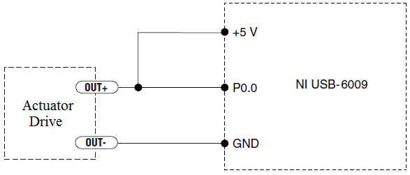
I have an actuator Bimba Original line electric with a motor continuous integrated with encoder, drive and the controller. The drive has a programmable digital output that I put as a tachometer output that emits pulses of square wave 100 per turn of the engine. I put the engine to make a total of 56 rev in 22 dry. I want to measure the speed of motor rotation labview real-time and synchronize it with a few other analog input signals. I wired the actuator for the USB-6009 case as shown below.
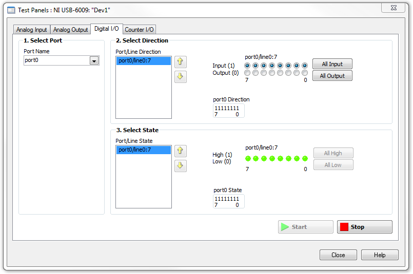
I opened the test i/o digital USB-6009 Panel and fix all the lines of port 0 as inputs. However, when I click on start and run the actuator, p0.0 led flashes, as indicated below.
Shouldn't the led blink in response to revolutions of engines?
I want basically to collect the drive pulse signals and convert them in rpm on labview.
ahsan2 wrote:
I have it wired correctly?
It would help if you do not attach the HIGH signal. Remove the + 5V in the circuit.
-
NI USB-6009 digital outputs are active when connected to a PC - I'm not that
I have a small problem:
All outputs digital NI USB-6009 module become active when the module is connected to a PC when no VI is running.
As soon as I start my VI, which controls the module, all the outputs are disabled (now inactive).
How can I achieve this, outputs are inactive if the module is connected to a PC with no program running?
johanneshoer wrote:
I have a small problem:
All outputs digital NI USB-6009 module become active when the module is connected to a PC when no VI is running.
As soon as I start my VI, which controls the module, all the outputs are disabled (now inactive).
How can I achieve this, outputs are inactive if the module is connected to a PC with no program running?
The USB-6008/6009 case has a pull-up internal (4.7 kOhm) resistance. This causes the outputs digital on the device to have a startup logic high State. t is not recommended to use some sort of resistance of menu drop-down. However, what you can do is add octal buffer like the 74HC541 stamp and a digital output to control the sorting of the 74hc541 state mode. Connect the OAS and CEO input signal. A Summit on the pins of the latter will be sorting the output of the buffer State. Therefore, no output signal will be present until you pull the stems of low control. The USB-6008/6009 case have a 5 volt output (200mA max), you can use the buffer.
-
6534 PCI for digital output finished generates a continuous output
Hello
I use 6534 PCI for my application, where I generate a digital output, a model finished variable length in a continuous loop. the code runs without error, but I'm not able to justify the behavior of the map. I intend to use the code inside the while loop as a Subvi and if I change the 'command' at the entrance table during each call to the Subvi, the output should vary according to the directives of the entry of the 1 d array.
But this is not the case, the loop displays the previous value that has been given to Scripture DAQmx. If the control panel is changed the output instantly does not change. It takes a while before the actual output changes. The length of the array command I give is also 88 & 133. When I realize that the output is wrong, I disable the DAQmx write vi by a structure of the case, I would expect an error that the output buffer is empty, but rather the old value is generated whenever the start Daqmx vi task is exectuted without.
My tax any problem is that the output buffer is not get replaced with the new value, but I'm specifyng the size of buffer, performing a registration every time and start the task, waiting until the task is done and the task stop. Each stop & writing should delete and empty the buffer, but I did not understad what goes wrong.
Also, I thought that maybe that orders are put in queue up in the output buffer, acual generation is not as fast as the call of the DAQmx write & start, but if that's the case then even if I stop the vi the generation should be until the buffer is empty, but that doent happen VI, break breaks of generation. the number of iterations is equal to the generated models. If anyone can help as to what could be the problem? fi
nd code attached below.
Hello
If I understand the problem you are experiencing, then the reason for the typical behavior when you run the VI, it is that you are not clearing the DAQmx task whenever you intend to go for a fresh DIO write. You stop just the DAQmx task that seems however to clear the buffer on board space.
With this post, I am enclosing a VI of the sample that should work according to your expected behavior. You can even call this VI as a Subvi and can use it to update the DIO port with a digital model of variable length fees. Another fact that I would like to point out, is that, once you have initalised one table, it is not possible to reduce the length of the array. You can only increase by adding new elements. According to your needs given that the digital model that needs to be updated will be of variable length, each time you cll the Subvi, you must create a freash of appropriate length and feed it as input to the Sub - VI. Inside the Subvi, according to the length of this array of entry appropriate buffer space is allocated.
Do trust this solution help solve you the problem, otherwise do not hesitate to go back.
Best regards,
Sagar G yapi | Application engineer | National Instruments - India
-
Pull-up external USB-6009. digital output (open collector) allows onboard external + 2.5 V output?
Pull-up external USB-6009. digital output (open collector) allows onboard external + 2.5 V output?
Hello
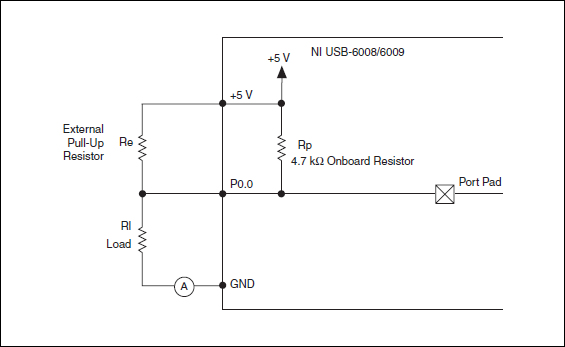
I want to config output digital USB-6009 to + 2.5 V above and 0 V digital output low. I know I can config USB-6009 digital output open collector with resistance to pull-up external, that can be applied with + 2.5 V power source.
My question is: can I use USB-6009 Board + 2.5 V output as the current source of resistance to pull-up? What resistance is a good number for the resistance to pull-up, if I can use this configuration?
Thank you much for the help.
Cathy
Hi Cathy,.
The digital USB 6008 front-end server looks like this:
So, there is actually an internal pullup to 5V 4.7 kOhm resistance when the device is configured to open collector.
If you want to display 0 to 2.5 V, I would look in a resistance of polarization of 4.7 kOhm between c and ground (according to the rest of your tour).
Best regards
-
Digital output of 6289 USB to the function generator
Hi ppl.

I have a DAQ USB-6289 card I use M series to interface with a programmable frequency AD 5932 generator (hope it's not breaking all the rules
 )
)In the datasheet of the http://www.analog.com/en/rfif-components/direct-digital-synthesis-dds/ad5932/products/product.html AD5932
It is the interface series (FSYNC, SCLK, SURLABASEDESDONNEESDUFABRICANTDUBALLAST).
I'm using LabVIEW to generate a digital output and help the Council 6289 to send the signal to the ad5932.
The problem is the following:
(1) I am an engineer in chemistry and new LabVIEW and electronics
(2) I don't understand how the digital signal and the FSYNC SCLK and SURLABASEDESDONNEESDUFABRICANTDUBALLAST are related... Sorry for the very basic question...

Hope that's not too much to ask, but if someone could suggest a tutorial or examples it would be EXTREMELLY appreciated...
Thanks for any input because I'm really stuck on this point.
See you soon
You need to find is the complete technical data on the A/D. Who will explain what each of these pins and the time served. It looks like an SPI interface. OR sell the 8451 for this programming. You can or perhaps are not able to use the 6289. I recommend a search of "SPI" to see if anyone has created a VI.
-
Hello guys,.
I am trying to create a simple VI to generate two outputs analog square with USB-6009. Each output supplies a LED and it is necessary that single LED shines at the time - so when Out0 is active, Out1 is zero and the other way around.
To get started, I created a VI in which the goods are made manually by Boolean and it works fine (square v1.vi of signal).
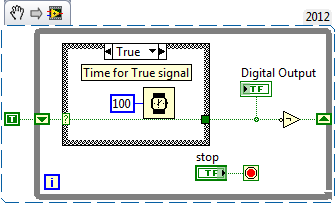
But I need the output to switch automatically after the amount of time given (I needn't of high frequencies, at about 1 Hz). To do this, I changed "square wave v1.vi" in "square wave v2.vi" and set the Structures of the case in an another While loop which would be timed by the wait function (ms). The idea was that the loop internal would turn the output rate of frequency while the outer loop would ensure a continued implementation of the programme. But the reality is very different and my low level of competence (this is my first VI) let me down. Could you please help me out of this? I appreciate all the advice.
To summarize: The VI must be continuously running program that generates two dependent signals with adjustable amplitude and opposite phases (Out0, when active, Out1 is zero and vice versa.). Signals must be switched automatically to the given frequency.
Here's a simple flip-flop - while time the loop runs, the Boolean line connected to the digital output passes from true to False to True... with the schedule determined by the time you put in waiting for him (note that you can have regardless of the different times for the true = on and False = off case). Of course, the life of signal (represented by 'Digital output') 'inside' this loop - you have to put the 1 point 1Line DAQmx VI write digital Boolean inside the loop, or find a way (for example, a queue) to get the data between the inside and outside.
-
Synchronization of analog and digital output with the external sample clock
Hello
First of all sorry for my English, I will try to explain what I want to do.
I want my PCIe-6321 to send two custom signals (modification sawtooths) on a mirror controller. I would also like to generate output with my card at the beginning of each tooth of saw. Everything must be synchronized with an external k-clock signal of 100 kHz. The idea is that whenever the PCI receives a trigger to external clock, it sends two analog output voltages and when he received 1024 clock ticks it will also send a pic of triggering TTL. What I do is first prepare the map and after that in a loop sending and modifing the output values of the two signals and at the same time send a digital signal Boolean in each arch, so when's done it 1024 iterations of the loop I send an event to the digital port. Attached you can see.
The problem is that I don't know how to synchronize both. Can I use the sample clock just to the analog output? I can use sample for the two outputs clock, or do I need to use the output of the meter? If don't know how to use it here.
If I do nothing else bad/wrong, I would be grateful for feedback.
Thanks in advance,
PabloI don't know how but I find the solution. I'm generating more than a positive value (as I was triggered maybe very fast the oscilloscope has been absent there). If I put the sample clock of digital output to use the sampling/ao/Dev1 clock that it doesn't, but if I put to use the same source as the OD (terminal where my external clock is connected), but the trigger to start the DO to be Dev1/ao/StartTrigger this works. I don't really know why, but it does.
Thank you for your patience and your help. I put here the final code.
Maybe you are looking for
-
Power without the grounding on the Satellite A100-02 b
Hello is there any supplys power to my Satellite A100-02 b without grounding?I need such a diet because when I use my laptop with a sound I hear noises if my power is connected. So I think it's because of the grounding. Thank youMatze92
-
Looking for Satellite P100-PSPA3U of the driver for XP Pro SP3
Hello I tried the driver for the Toshiba Satellite P100-PSPA3U. I am trying to get the driver on the European site, but I could the found.I'd really appreciate it if someone could help me with this problem. The laptop has the English version of Windo
-
I get this error code when I try to install the latest version.Lightroom CC / update from 6 July 2016.Failed installation. Error code: U44M2P7Thank youPhillip
-
Got the new update, can't find a way to highlight the text...
Got the new update and it works very well Instructions say to copy text email or web a "yellow Highlight" is displayed. What is this reference to? This isn't even proper English... In the menu, I can choose SELECT ALL, but what happens if I want to
-
can I send selected in adobe reader ms pages? at present, I can only send total number of pages