Generation of signals (c) FIFO PXI-6225
Hello.
My user requests an upgrade a system existing.
I'm an analog input I need to convert to a digital waveform. As the analog input varies, I need to be able to vary the frequency of the digital wave to match. Just recently, I discovered that I should probably use a line in Port 0 on my PXI-6225. I tried using digital model Generator.VI and writes the result to a Write.VI DAQmx. I wish that some checks before I'll and rewire my material that I'm on the right track.
Thanx.
Hi Bill,
So it seems that you need to output a pulse train that changes frequency proportional to the voltage of your analog input (or proportional to an input of pulse train). If this is the case then the best way to do it is actually NOT with correlated digital i/o but rather with one edge counters. He would use the PFI lines rather than port 0.
I would like to start by this example that shows how to change the frequency of an output of TTL meter on the fly:
Output frequency of meter to change on the fly
You can read your task of entry in the same line as the generation (or you can try instead an architecture of producer/consumer ). I hope this helps, let me know if you have any questions!
Best regards
Tags: NI Hardware
Similar Questions
-
Problems to use two scb-68 has the NI PXI-6225
Dear nor Forum,.
I have a chassis NI SMU-1078, with embended OR PXIe8135 controller. One of the slot is busy with a PXI-6225. I for a long time successfully using 1 connection SCB-68 block a with the PXI-6225. Now, I need another channel to analog output on top of OD uses two that I am current. I plugged another SCB-68 connector Panel at the PXI6225, but I could not see analog outputs on this second bedroom. I could not see more channels to DAQmx AO create channel VI
The PXI-6225 has only 2 analog outputs. The second connector only has analog inputs.
If you need more than output analog, you can take a look at the SMU-6738, which includes 32 analog outputs.
-
Hello, I am trying to get the DDK AI working for a PXI-6225 card examples and still receive an output value of 10.599597. I HAVE 0 (68 pins) short-circuited for AI 8 (34 pin) that should lead to a value of 0.0 VDC. I also tried to connect a battery of 9V to terminals and stilll get the 10.599597 value. I know that the Council works because I see all the correct values in the measurement and Automation Explorer. I have already programmed a PXI-6511 and PXI - 6513 PXI - 6704 Council using the DDK examples so I'm quite familiar with the DDK sample Setup, but I can not get this example to work, no matter what I do. Help, please!
Hi computer guy.
What example DDK are you using? Make sure you remove the call to adcReset() because it is only applicable to 625 x materials. Additionally, make sure that convert it output polarity (selected by aiPersonalize()) and the gain setting and match of research (see ai.h and scale.h) scale factor values you are going for.
I've also posted a few specific tips 6225 in this thread.
I hope this helps.
-
Generation of signals of segment
Hello!
How is it possible to generate such a signal (photo attached)?
https://pp.VK.me/c622024/v622024951/33e6f/I3zJNTMGiU0.jpg
A link to the answer (if there is one in this forum) would be great.
Thank you
This may work for a graph where it will automatically draw lines between points. But if it comes to the generation of signals, it won't look like that.
Look at the function of ramp model. Which allows to build the parts in signal Hill and initialize the array to build from scratch the parts and flat parts. Then use table build with CONCATENATE entries in order to combine these tables into one.
-
I can't read thermocouples on the PXI-6225-series M 1 connector.
I'm reading 30 measures by thermocouple in differential mode. I use AI0 as the CCM. Attached are the connections that I use. Negative contributions all relate directly to the GND AI.
I have no problem to read the thermocouples in slot 0 (AI1 by AI 7). I have install Connector 1 direct feed by mode (switch 1 & 2 right and switch 3 upwards). In MAX, I get a normal reading, but it does not vary by heating the thermocouple. In my real program, it is as if there is nothing connected. Any ideas as to what I can hurt?
Thank you
Mark
Mark,
Thanks for posting. I think the question might be to see you about the how the SCB-68 must be configured in mode of direct crossing to be used with the connector 1 on the PXI-6225. When the switches on the block are defined for a direct crossing, the Council is not connected to the CJC. Do not have a connection to a CCM on this connector could cause this problem.
A potential solution, you can try is to connect a temperature probe to AI16 and follow the steps in this KB, using that channel instead of the CJC channel. Let me know if it helps!
Kind regards
Joe S.
-
acquisition and generation of signals synchronized redpitaya impetus
Hi, I'm new in collaboration with redpitaya and labview.
I've been trying to get the example of the "generation of signals a synchronized pulse and acquisition" has worked with labview. But I have a few problems.
FISLY, when I downloaded it, some varibles where the wrong type, so connection could not be made (fig. 1). So I use a block converter (from string to number) in order to solve this problem, because he wan't work I changed directly two of the entries from string to number and I kept the conversion of the rest of the string variables (picture 2).
I was getting an error, but the example did not work properly. When I play run, it only resgisted noise, but not the signal that it was created (image 3). I changed the table (chanel I used, amplitude, frequency, the shape of the signal itself)
To check that the wire and the RF input and output was OK I tried to change the signal, put it on my hand and the change in signal to noise, but there was still noise (picture 4). I tried each entry and exit, but I still have the same signal: noise.
To conclude: I can't do this example to work.In addition, I have a question on this example, the labview and Redpitaya libraries: How can I change input 1 input 2 and from exit 1 to exit 2, because I don't see that option 1 of chanel and chanel 2, but it does not say what combination of input and output is. and I can't find the block to edit entries and exits
If anyone has had the same problem, how to solve it?
Thanks in advance!
Entries you 'fixed' are not numbers, looks like they are channel names. The representation has changed some time ago, but it is an example of the former.
Mike...
-
Generation of signals to the NI PXI-6713, on different channels
Dear community LabVIEW,
anyone could help me please, I beg you, by the following. I want to generate sine wave using NI PXI-6713, with the same frequency of sampling, but in different times. Let's, first of all, I need to launch the generation on channel 0 and after a few seconds - start generating on channel 1, continuing to generation on channel 0 (the reason - parallel test several EHR, so steps generation EHR may occur at different time). Is this possible?
I tried to create several task for each channel and launch the generation for each channel separately, but I got the error message "-50103: the specified resource is reserved." The operation could not be performed as indicated. ».
This means, that I can't start build on different channels at different times, and I need just to create a task for the channels, on which the signal will be generated and start production at the same time?
Thank you very much in advance!
Because the device has a clock convert, you must use a single task to more than one channel.
-
2 digital signals keep using pxi 6544
Hello
I wonder how I can generate 2 digital signals that continues and I will able to make even phase, or different phase 1/2, or 1/4 different phases. And I need them to be able to their output in any channel (free) my PXI 6544.
I've seen examples of generation (no script), but most of the examples shows just how to generate data in parallel. Generating script I use to achieve this? Repeat for the thing?
Kind regards
Yan
-
Generation of pulses using NOR-PXI-5421 FGen
Hello Sir/Madam,
Question:
We use the Funktiongenerator NOR-PXI-5421 and just want to generate a pulse, because it can be done in almost all cheap Funktiongenerator.
Unfortunately, I can't find a way to tell the Funktiongenerator to generate a pulse. I can generate Singals as I like, but don't know how to generate a single pulse.
Perhaps you have a program that gives me this opportunity.
Thank you for your support.
Hi Jens,
You can try to use the Council 5421 scripts. The following examples of LabVIEW: "Fgen Arb Script.vi" or 'Fgen switch between Waveforms.vi' use of script to generate signals, you can create a script that generates a single DC pulse of high level in the same way.
I hope this information helps you.
Best regards
Blase
-
Low signal Amplitude on PXI-4461
I currently use two PXI to generate an analog signal through LabVIEW 2009 to an oscilloscope:

PXI-4461 runs below the attachment (properly labeled). It also produces the green line on the graph. It seems OK on the oscilloscope.
PXI-5412 runs the other (properly labeled) attachment below. It produces the yellow line on the graph. This amplitude is measured properly (or so it shows in the margin of the image), however it gives me a warning of "Low Amplitude of the Signal" and displays the wave that is much smaller than the "correct" version of the 4461.
* Note: I guess it's possible that the PXI-4461 (green) is false and the PXI-5412 (yellow) is right, but as the PXI-5412 (yellow) produces the error, I am led to believe that this is the problem.
I could use help to find out what could be causing this inconsistency and how I could do to fix this problem.
This has nothing to do with LabVIEW. This is the oscilloscope all partners. The reason why the yellow signal is smaller than green is because your ranges are different. Look at the bottom of your oscilloscpe: Ch2 said "500mV by division" while channel 3 said "1V by division. You probably get a "low signal amplitude" because you report is less than '2 divisions' and offer thus the scope allows you to change this. There is a button named "Autoscale" your bezel that you can hit if you want.
-
Photon counting using the FPGA of the series R. problem generation TTL signals
Greetings,
I try to use the R series FPGA to read and count the pulses TTL of a discriminator (count of photons of the Hamamatsu C9744 unit) connected to a PMT (Hamamatsu-H7422P-40). The release of PMT looks fine (signal.png H7422P-40) but the discriminator wasn't able to generate corresponding TTL 5V pulse. There was some scattered and random spikes, but nothing significant. Instead, the only stable the PMT signal is a single + 5V pulse no matter how, I adjusted the PMT (C9744 output.png) control voltage. The PMT and the discriminator is connected by an ordinary BNC cable 50 ohms.
I am really confused because it was supposed to be a really simple installation. Anyone have a similar question or have similar Instrumentation (but no problem) configuration? Comments/suggestions are greatly appreciated.
Thank you very much in advance!
Hi Kelli,
Thanks for your help. Sorry it took so long to get back to you.
I actually found the question. The discrimination of the Hamamatsu unit level is set too high that all signals got filtered. After adjustment of the threshold of manuallyt, I was able to get the camera TTL pulses. And 7842R worked correctly for count impulses. Everything works fine now. Thanks again for the input.
-
generation of signals DAQ 6133
Can use of BNC-2110 and DAQ board 6133, I generate a sine signal and the signal sine output?
Hi WG_23,
Wondering if you can use your 6133 to generate a sinusoidal signal and connect it to the BNC-2110 to connect it to something else? The 6133 does not have the analog output capabilities, so you will need to do this, use another card.
Best,
-
generation of signals using DAQMx.vi
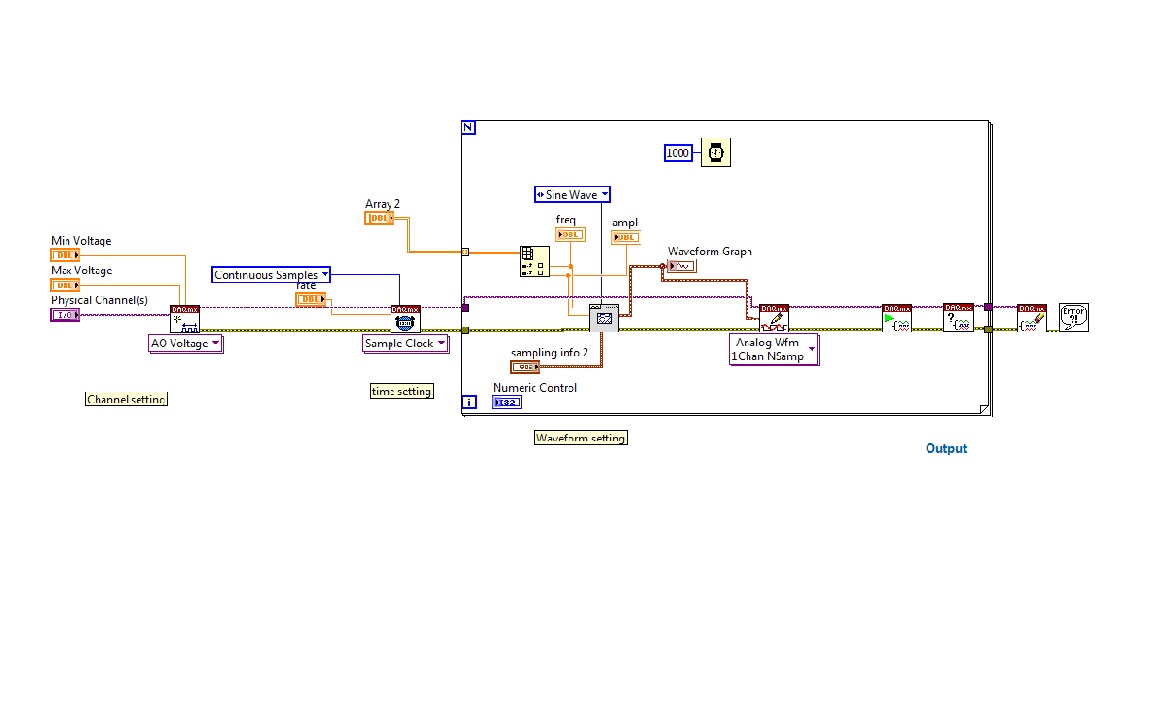
I'm trying to generate signals with a generator block functional VI, with a lop fill and table with values of frequency and amplitiude
as in the diagram below.
When programs run at the end an error message pop up
- Error-200479 occurred at DAQmx start Task.vi
-Specified operation cannot be performed with task is running.
-
Syncronize to acquisition of data with the generation of signals
Hello everyone,
My request is generate pulses on the output of two different to drive two LEDs and acquire detected pulse signal amplified photodiode.
Actually pulses are generated by starting the writing on the analog output, and then start the acquisition (I need 200ms on average), stop the acquisition, turn off the driving LED and develop the acquisition and record the results.
All this in a cycle it takes about 1.5 seconds to run.
Next step would be to drive the outputs with a waveform (duty cycle of 50% of width of 250 ms) and acquire the signal of the photodiode in synchronization with the edge of the pulse.
I tried to use the trigger function, but the examples are not clear on how to do it.
I use NI 9205 or 9215 to acquire signals.
Is there a particular entry to be used as a trigger?
Thank you very much for your attention
Hello
I found that NI 9205 has inputto that one be used as trigger signal, i.e. AI0.
At latest
Eugenio
-
Generation of signal Pulse width modulation for ULx
Hello
I'm trying to produce an analog waveform (IE square wave) with an option to control the cycle.
I went out with a Measurement Computing card, which uses the libraries of user ULx.
There are many examples of do what I want to use DAQmx, but all those who use ULx have no option to control the duty cycle.
Can anyone help?
Thanks in advance.
Hi ben,
your hardware ULx even does support the PWM outputs? Support the tasks out of meter?
It is not only the software, the material must also support your needs!
Maybe you are looking for
-
The listed but module does not exist in the Solution Explorer.
A few weeks earlier, an add-on software malicious has been installed to my current Mozilla Aurora profile. I have it turned off in the menu Add-ons, but no delete option was present. I used: "subject: support" to find the name in which it is declared
-
I try to run the installation on my new webcam and it tells me I don't have enough disk space, what is true on the D drive that should be reserved for the only programs of systems, my C drive where I want to install has over 140 GB of free space and
-
Upgrade from Vista Home Premium to Windows 7 Ultimate
I have a Dell Studio 64 bit machine with Vista Home Premium installed. My new employer gave me their Windows 7 Ultimate corporate software to install. I checked with the Compatibility Wizard and it says I can upgrade from Vista Premium to 7 Ultimat
-
Signature behind the proxy in eclipse
I have the files sigtools.csk, sigtools.db and sigtools.set and I managed to import the signature in the eclipse. But the problem comes when you sign with the same. I get the error "General failure. Please try again. Server is might be unavailable.
-
Score on Micsroft Solitaire Collection has lost
I played Microsoft Solitaire Collection for several months. When I logged in today all the games that I won for October were missing. The statistics were correct for previous months. Is there anyway that I can restore my partitions for October?