Generation of signals of segment
Hello!
How is it possible to generate such a signal (photo attached)?
https://pp.VK.me/c622024/v622024951/33e6f/I3zJNTMGiU0.jpg
A link to the answer (if there is one in this forum) would be great.
Thank you
This may work for a graph where it will automatically draw lines between points. But if it comes to the generation of signals, it won't look like that.
Look at the function of ramp model. Which allows to build the parts in signal Hill and initialize the array to build from scratch the parts and flat parts. Then use table build with CONCATENATE entries in order to combine these tables into one.
Tags: NI Software
Similar Questions
-
acquisition and generation of signals synchronized redpitaya impetus
Hi, I'm new in collaboration with redpitaya and labview.
I've been trying to get the example of the "generation of signals a synchronized pulse and acquisition" has worked with labview. But I have a few problems.
FISLY, when I downloaded it, some varibles where the wrong type, so connection could not be made (fig. 1). So I use a block converter (from string to number) in order to solve this problem, because he wan't work I changed directly two of the entries from string to number and I kept the conversion of the rest of the string variables (picture 2).
I was getting an error, but the example did not work properly. When I play run, it only resgisted noise, but not the signal that it was created (image 3). I changed the table (chanel I used, amplitude, frequency, the shape of the signal itself)
To check that the wire and the RF input and output was OK I tried to change the signal, put it on my hand and the change in signal to noise, but there was still noise (picture 4). I tried each entry and exit, but I still have the same signal: noise.
To conclude: I can't do this example to work.In addition, I have a question on this example, the labview and Redpitaya libraries: How can I change input 1 input 2 and from exit 1 to exit 2, because I don't see that option 1 of chanel and chanel 2, but it does not say what combination of input and output is. and I can't find the block to edit entries and exits
If anyone has had the same problem, how to solve it?
Thanks in advance!
Entries you 'fixed' are not numbers, looks like they are channel names. The representation has changed some time ago, but it is an example of the former.
Mike...
-
Generation of signals to the NI PXI-6713, on different channels
Dear community LabVIEW,
anyone could help me please, I beg you, by the following. I want to generate sine wave using NI PXI-6713, with the same frequency of sampling, but in different times. Let's, first of all, I need to launch the generation on channel 0 and after a few seconds - start generating on channel 1, continuing to generation on channel 0 (the reason - parallel test several EHR, so steps generation EHR may occur at different time). Is this possible?
I tried to create several task for each channel and launch the generation for each channel separately, but I got the error message "-50103: the specified resource is reserved." The operation could not be performed as indicated. ».
This means, that I can't start build on different channels at different times, and I need just to create a task for the channels, on which the signal will be generated and start production at the same time?
Thank you very much in advance!
Because the device has a clock convert, you must use a single task to more than one channel.
-
Photon counting using the FPGA of the series R. problem generation TTL signals
Greetings,
I try to use the R series FPGA to read and count the pulses TTL of a discriminator (count of photons of the Hamamatsu C9744 unit) connected to a PMT (Hamamatsu-H7422P-40). The release of PMT looks fine (signal.png H7422P-40) but the discriminator wasn't able to generate corresponding TTL 5V pulse. There was some scattered and random spikes, but nothing significant. Instead, the only stable the PMT signal is a single + 5V pulse no matter how, I adjusted the PMT (C9744 output.png) control voltage. The PMT and the discriminator is connected by an ordinary BNC cable 50 ohms.
I am really confused because it was supposed to be a really simple installation. Anyone have a similar question or have similar Instrumentation (but no problem) configuration? Comments/suggestions are greatly appreciated.
Thank you very much in advance!
Hi Kelli,
Thanks for your help. Sorry it took so long to get back to you.
I actually found the question. The discrimination of the Hamamatsu unit level is set too high that all signals got filtered. After adjustment of the threshold of manuallyt, I was able to get the camera TTL pulses. And 7842R worked correctly for count impulses. Everything works fine now. Thanks again for the input.
-
generation of signals DAQ 6133
Can use of BNC-2110 and DAQ board 6133, I generate a sine signal and the signal sine output?
Hi WG_23,
Wondering if you can use your 6133 to generate a sinusoidal signal and connect it to the BNC-2110 to connect it to something else? The 6133 does not have the analog output capabilities, so you will need to do this, use another card.
Best,
-
generation of signals using DAQMx.vi
I'm trying to generate signals with a generator block functional VI, with a lop fill and table with values of frequency and amplitiude
as in the diagram below.
When programs run at the end an error message pop up
- Error-200479 occurred at DAQmx start Task.vi
-Specified operation cannot be performed with task is running.
-
Syncronize to acquisition of data with the generation of signals
Hello everyone,
My request is generate pulses on the output of two different to drive two LEDs and acquire detected pulse signal amplified photodiode.
Actually pulses are generated by starting the writing on the analog output, and then start the acquisition (I need 200ms on average), stop the acquisition, turn off the driving LED and develop the acquisition and record the results.
All this in a cycle it takes about 1.5 seconds to run.
Next step would be to drive the outputs with a waveform (duty cycle of 50% of width of 250 ms) and acquire the signal of the photodiode in synchronization with the edge of the pulse.
I tried to use the trigger function, but the examples are not clear on how to do it.
I use NI 9205 or 9215 to acquire signals.
Is there a particular entry to be used as a trigger?
Thank you very much for your attention
Hello
I found that NI 9205 has inputto that one be used as trigger signal, i.e. AI0.
At latest
Eugenio
-
Generation of signals (c) FIFO PXI-6225
Hello.
My user requests an upgrade a system existing.
I'm an analog input I need to convert to a digital waveform. As the analog input varies, I need to be able to vary the frequency of the digital wave to match. Just recently, I discovered that I should probably use a line in Port 0 on my PXI-6225. I tried using digital model Generator.VI and writes the result to a Write.VI DAQmx. I wish that some checks before I'll and rewire my material that I'm on the right track.
Thanx.
Hi Bill,
So it seems that you need to output a pulse train that changes frequency proportional to the voltage of your analog input (or proportional to an input of pulse train). If this is the case then the best way to do it is actually NOT with correlated digital i/o but rather with one edge counters. He would use the PFI lines rather than port 0.
I would like to start by this example that shows how to change the frequency of an output of TTL meter on the fly:
Output frequency of meter to change on the fly
You can read your task of entry in the same line as the generation (or you can try instead an architecture of producer/consumer ). I hope this helps, let me know if you have any questions!
Best regards
-
Generation of signal Pulse width modulation for ULx
Hello
I'm trying to produce an analog waveform (IE square wave) with an option to control the cycle.
I went out with a Measurement Computing card, which uses the libraries of user ULx.
There are many examples of do what I want to use DAQmx, but all those who use ULx have no option to control the duty cycle.
Can anyone help?
Thanks in advance.
Hi ben,
your hardware ULx even does support the PWM outputs? Support the tasks out of meter?
It is not only the software, the material must also support your needs!
-
generation of signals USB-6009
Hello!!
Can someone suggest me how to generate a pulse of 3V/0V to output pin (a01) to change the transistor...
requirement is: 1ms - 3V and 400ms-0V permanently...
With the help of NOR-USB-6009
Thanks in advance!
The short answer is that you cannot do with the USB-6009 case. Outputs analog device are timed software and 1 ms pulse is too fast for the outputs timed software. According to the computer, OS and other software activities and perhaps the phase of the Moon, you can only expect rates to update AO 100 Hz to a few hundred Hz and there may be considrable timing jitter at these rates.
You must obtain a DAQ device with hardware timed AO.
Lynn
-
acquisition and generation of signals
Hi all!
I'm new to labview and I need help. I am trying to acquire and generate data to two devices simultaneously. I reached successfully synchronous acquisition, but the problem I have is that whenever I run the program it is not compatible. Can someone help me and take a look at my code?
-
stop propperly generation of continuous signals (analog)
Hello
I want to generate a continuous wave-output analog (sine, for example) using NI-Daqmx. The example program in http://www.ni.com/example/29872/en/ works very well and does everything I want, but there are two problems:
(1) I want to count the number of waveform periods that are executed.
(2) if I press the stop button (or another event occurs), the program should not interrupt the generation of signals anywhere. It should complete the last period and than stop running.
I tried to solve this problem in timing the loop while I have exactly one period per loop. It works very well for small frequencies, but for higher frequencies (for example 100 Hz - 1000 Hz) not more

A second method used ends generation (always generate a period in a loop). But with this method there is an another serious proplem: if I make higher frequencies (for example 100 Hz or more) the loop requires too much time and the signal isn't continuous more because there is a short break between each period.
I am new to LabVIEW, could find a solution so far and would be very happy if someone could help me with this :-)
The key step is to make sure that the stop button is not connected to stop your loop. In a 'simple' control system, there is a single loop, and the stop button (and everything else!) lives inside the loop. When you press Stop, if it is connected to the loop Stop, everything stops.
What you want is for the Stop button to report a condition, namely 'Stop at the end of the current cycle'. If you generate data of a point at a time, you should be able to tell (by looking at the phase of the signal) when you are at the end. One thing you could do would be to ask (for each iteration of the loop) "I am the end cycle, i.e. the Phase 0? If this is true, and the Stop button is pressed, Stop.
BS
-
Generation of data and acquisition of high frequency problem
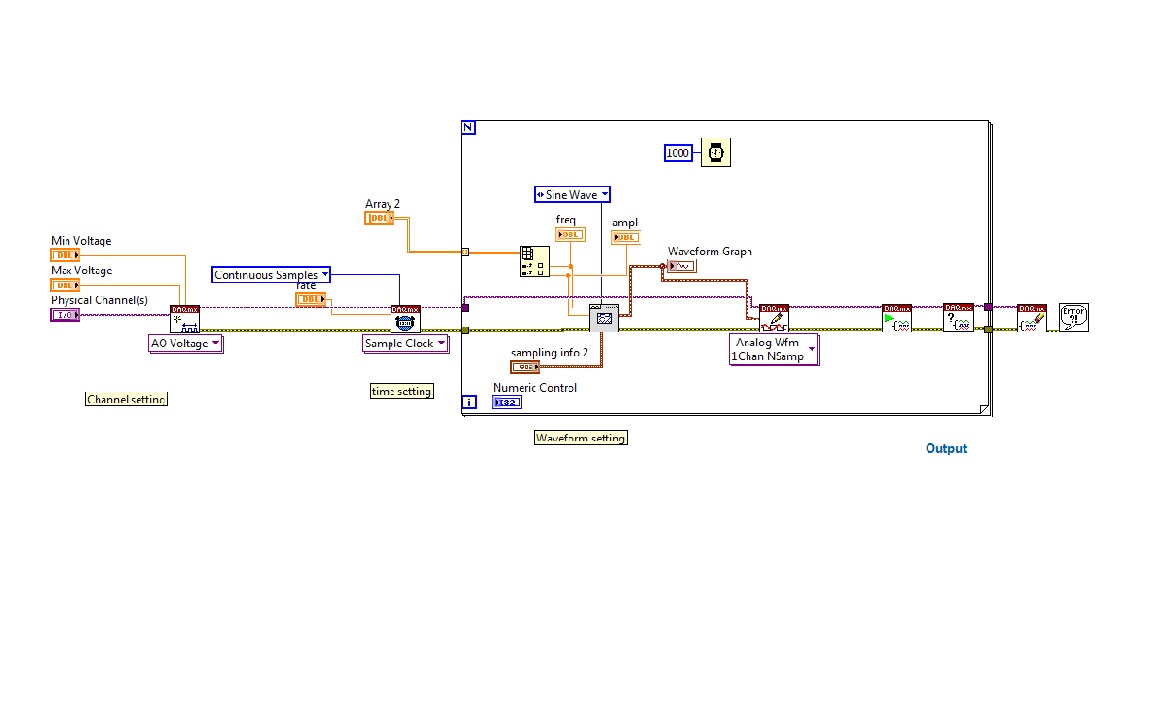
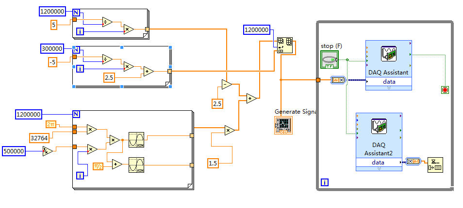
The fitting requires a fishing signal (32,764 KHz) saw tooth (0.3 Hz) signal output to drive the laser and acquires the signal from the output of the detector. I use the NI USB-6356 data acquisition with the speed limit of 1.25 MECH. / s.
I put the generation mode like "Samples continues", samples of writing/reading of 1.2 M and 500K (Hz) frequency in the DAQ Assistant. I also tried 500K and 500K.
The scheme of vi is illustrated in the following figure.
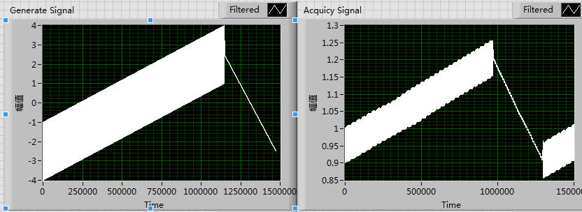
Of the front plate, the generation of signal is normal, which may be seen in the left side of the following figure. But signals a lot of periodic fluctuations that will appear if the right side of the figure. In addition, the siganl acquist go all the time.
I think it's maybe a few errors with my setting of the sampling frequency, I tried a lot of time for a change of pace, but it seems unnecessary.
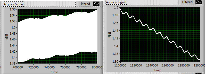
These fluctuations exist not only in the growing period but alos can be seen in the declining period, which is shown in the following figure:
I tried to solve this problem for almost a week and try a lot of different rate, but all fail.
Could someone give me any suggestions please? Thank you very much!!
Thanks SOSOSO much for your reply immediately every time!
This is my first time to write the Labview program with data acquisition
The attachment is the field of Vi.
I'll read the Web page that you offer, thank you very much once again!
-
Exceeded the output signal analogue of sbRIO9636?
Hey people so I got my sbRIO9636 of the sbRIO assessment package.
I was wondering if it is possible to transmit a signal from smulated via the analog output of my FPGA.
Basically, I have 2 signals I want to simulate who go to the analog output of the FPGA in a multiplier amplifier (this is a physical IC).
However, whenever I try to transmit the signal simulated in my output analog I get an error because the signal is 2D for the analog output is just a fixed point. Is there a way to get around this?
Hi Butterwaffle,
As noted Nick exit FPGA is point by point - you can write a single AO to both sample.
This is probably a good place to start:
Tutorial: Generation of signals with CompactRIO
http://www.NI.com/white-paper/4783/en
Hope that helps!
-
Weird behavior with Signal to simulate and loops
I'm having a weird behavior with Signal to simulate and while loops. Attached a photo of my program. The problem I have is that when I use Stop to stop inside while loop, then use to restart the inner loop, simulate Signal instantly generates a bunch of points of data between when I pressed Stop and Go. By example, if I stop for 5 seconds, wait 5 seconds, then press Go, it will instantly generate data for t = 5 t = 10. What I need is for the generation of signals to stop when I press stop and continue where it left off when I press Go. How can I accomplish this? I have no idea why he exhibits the behavior described in the first place.
Hi optometry.
Can you give us a screenshot of the configuration window for the VI express to simulate signal? I was able to reproduce the problem when I used "Simulate the time of acquisition" at times, but the VI's are featured as you described you wanted when I used "run as fast as possible." Have you tried this setting?
Maybe you are looking for
-
More memory to an application.
-
want available firefox but not as default browser
I am trying to configure Firefox as one of my browsers. It supports applications that are not available on my default browser, Internet Explorer. But when I try to download Firefox it ask if I want him as my default browser. No I'm not, because my pr
-
I can't answer received no Apple users iMessages. I checked all my settings and they seem to be set correctly, it has occurred a random recent request to resign in my Apple account. Initially it would not accept my login iCloud, but then he did, and
-
BUGCODE_USB_DRIVER blue screen of death
Hi, I got the bsod up to several times a day now for the past week, still the same error code: STOP: 0X000000FE (0 x 00000006, 0x00000001, 0x00000008, 0X87468C68) It seems to happen randomly, a few days, using msn messenger will cause, other times, o
-
BlackBerry smartphones can not synchronize the new BB with Desktop software
I lost my Blackberry Curve 9300 a few months ago and just recently I replaced it with a used Blackberry Tour 9630. I tried to connect my tour to the desktop software, I had downloaded for my old phone, but it wouldn't sync. So I tried to uninstall an