Hardware timing on PXI-6259
I'm having a problem of selection of a clock for the PXI-6259. I've seen several posts on the forum on this issue, but the solution seems to be "read the manual"; I am not able to total, try it.
I have a chassis with an analogue 6723 static on the map and a 6259 multifunction data acquisition. I provide 4 sets of 2 digital inputs: a guideline and a pulse line. The user selects a number of impulses, a pulse width, and a destination for the pulse train. I use the number of pulses and pulse width to set up a digital waveform clocked. I can write the direction static c on the 6723 and the train of pulses at the timed HW DO on the 6259.
My problem is to select a clock for the pulse train. I tried using the sample AO clock and the sample clock HAVE to give me the ability to adjust the pulsewidth. I add the additional sample for the "wait until what Done.vi", but it times out when one of these clocks are used. If I use the time base of 100 kHz, the vi works well - but only for a 10us impulse. With the help of the time base destroyed my ability to change the pulse width.
I have attached the screw below; He let me just tie three.
The vi parent - control Tach, Full.vi
The creation of impulse vi tasks - create Pulse Channels.vi
The output vi - generate Tach Pulse.vi
The RWA selector is a typedef that selects one of the four outputs to send the train direction of signal and pulse to.
The typedef of Direction is converted to a Boolean value to write to the direction of entry.
I first create an array of tasks for the static DO the map of 6723, a special track.
Then, I create an array of tasks for the pulse on the map of 6259, including the establishment of the clock. I do this by taking the desired number of pulses, doubling (each pulse takes two samples), then adding one to allow the impulse to settle. I also add another sample, in addition to that for the vi "wait until what". This is the vi where to select which one to use.
I then choose the task of a pulse and direction, enter the values in the buffer and start explicitly jobs. After that wait until done return, I stop the tasks.
Waiting until it times out (I used up to 10 s) am the AO or sample clock is used. If I remove the wait until done, I get a warning (task may have stopped before all the written samples) with no output pulse train. It works very well with a time base of 100 kHz, but of course its fixed and cannot make any other sample rate other than 100 kHz/10us.
I have three questions:
1. the main problem - what I'm doing wrong with the clocks?
2. I put the program in time loop to allow the sending of one of the 4 outputs. I can send reverse or forward impulses out even any number of times, but the VI produces an error if I try to switch to another output (turned off, so I don't have the exact error code; it tells me that the task is reserved).
3. is it necessary to replace the task in the table when I'm done with it (for example, replace the code table subset)? What is exactly included in the thread of the task?
Had some extended time for testing today, and I found a solution. It is much more complicated as the example shows, although it seems obvious, once I write it.
It takes two tasks and two knots of timing to accomplish the digital generation timed by material:
A single task and node of synchronization for the digital task, I had put in place already
A single task and calendar for an analog task node allow the sample clock. I needed an analog task with a channel not used AND a timing node. Analog synchronization node should have the same sample rate and the number of samples that the node digital synchronization, but the source entry should be left blank to use the default clock (sample clock HAVE for a fictitious analog input channel).
Sailing smooth after that. Thanks for the help and insight!
-Nick
Tags: NI Hardware
Similar Questions
-
Good afternoon friends,
I'm looking to synchronize a finishes analog output signal with a digital output signal end of same length (number of samples). Ideally, the signals should be identical except for the amplitude... 5V for life. I guess that this will require a trigger to start shared? Any who have an example or knows where I can find an example of synchronized finished AO and? My hardware is a PXI-6259.
Thank you
Zach
Hello Super!
Thanks for your post! One of the ways that I would like to synchronize your AO is to use the timing engine AO as your sample for both clock. In this way, you know that you are using the same sample that is generated on board the 6259 clock. Just be sure to start your task before your AO so that when when the AO starts and generates the sample clock the task sees the first front. Essentially you will be triggering the DO with the task of the AO. Take a look at the screenshot of the block diagram that I made that does exactly this. I checked with another DAQ card to ensure synchronization. Let us know if this helps and and take a look at this area of developer who talks about sync multifunction.
Synchronization of series M with LabVIEW and NOR-DAQmx
Have a great day great and let us know if this helps your applications!
See you soon!
Corby_B
http://www.NI.com/support
-
PXI-5122 and PXI-6259 read 2 channels simultaneously
There is a single PXI-5122 digitizer card and a PXI-6259 DAQ card in our PXI system, we use Labview and TestStand (model Batch) to test the multiplication Board simultaneously, sometimes up to 8 boards are tested. We have some problems, such as the results of the tests is not reliable and sometimes blocking of Labview. Everything works fine when test single board. Thus, we feel that multiply causing this problem of acquisition of string data. It's great, if someone has the same problem and we can share the knowledge. My question is as follows:
1. If two channels have been configured, read the two channel simultaneous cause blocking of the system or data damaged?
"lu niScope WDT.vi" is reentrant, we can use two Subvi to call the "niScope Read WDT.vi' access the two channels simultaneously.
2. If we set up a channel in another channel is reading the data, this situation will cause the search system or corrupt data.
Concerning
Samuel
Hi Samuel,.
You shouldn't have any difficulty to read several channels on your 5122 or between your 5122 and your 6259. You receive an error message when your test is blocked? What happens when your test is not reliable? Are you incorrect data and if so what is the data vs expected data acquired? You should be able to set both your channels in a single task, which would be using a read niScope WDT.vi to be used by the device. You are working from example or have you developed your own code? What version of the driver NOR Scope and NI-DAQmx driver do you use? You can find the driver version number in the measurement and Automation Explorer under the software section.
What kind of test are you running? Your PXI chassis is controlled by a computer or by an on-board controller? Evolution of the rate of acquisition has an effect on your program?
-
Hardware timed CI/CO, operation of PCI, I / AO with specific execution order
Hi all
I work with a USB-6361 NI data acquisition hardware and I'm writing a LabView 2011 program which sends a signal to my output device and reads several values of various measuring devices. I have a ramp voltage signal (in a table format) and I need to sequentially send the elements of this array on my AO device with very precise timing (ideally timed material). As soon as the value is written to the device of the AO, I need my tasks HERE and CI to record all available data and my task to send a single impulse before the next array element is sent to the device AO. All this needs very precisely timed such that if I perform a measurement on 1000 points in my table of ramp with a timing of 1000 Hz, the program will have exactly 1 sec. to run (less overloading caused in initialization and closing tasks) and produce a table of data consisting of 1000 steps of AI and CI. I had initially tried to achieve this by using a structure of sequence within a timed loop software, but because I won't get into multiple channels of Amnesty International and CI and tables of data, this has proved to be excessively slow. The other danger that I fear I could run is the case in which the LabView program runs more slowly than the process of acquisition data itself, thus causing data to write to the buffer and the measures being lost.
I didn't spend a lot of time working with the procedures, timing and synchronization, so I apologize if this is a rather naïve question - I'm having trouble reconciling restrict them inherent software and order of execution with the hardware timing. What is the best way to solve this problem? I can only think of two reasonable approaches to the problem:
(1) should I try to trigger my CI tasks and HAVE run on the completion of the task of the AO (and if so, how)?
(2) I have the CI and tasks run on a separate clock with a start delay initial light as to compensate for these tasks if they occur reliable after that each value AO is sent to my device?
Finally, I build an identical for a real-time embedded controller program of SMU-8100. The approach will be different in this case?
Thanks in advance for your answer.
I can give you an overview of the steps you'll need, but be ready to spend experiment a little time and some of these individual pieces of troubleshooting before you put them all together.
First of all, a X-series 63xx allows all you need to accomplish a very precise synchronization in hardware. When you then switch to a real-time controller, you must include an X-series device in the chassis to maintain this capacity of equipment.
Second, 1 kHz is not yet a challenge to LabVIEW to catch up with your hardware, even with powered lower RT controller. You just need to program the DAQmx tasks to let the hardware & driver do most of the work.
1. I would dedicate a counter of the 6361 to generate the clock shared for other DAQmx tasks. I tend to create a clock and operating cycle of 90-95% for this type of application of stimulus / response to the response time & maximum stabilization. Generate the stimulus at the cutting edge of the clock and gain response data on the edge of leak - before the next sample of stimulus. Call it the task of the clock.
2 set up a buffered AO task that uses the output of clock as the sample clock. Configure the polarity to be sensitive to the cutting edge (usually, this will be a rising edge). Start the task AO * before * starting the task of the clock.
3 configure tasks HERE and CI to use the output of clock as their clocks in the sample. Configure the polarity to be sensitive at the trailing edge. Start tasks I and CI * before * starting the task of the clock.
4. the output pulse should be a task of meter output, configured to generate a single pulse redeclenchables. Configure it to use the leading edge of the clock as the trigger signal output. Set the time of 'low' and the 'initial period' to equal precision<1 msec="" delay="" you="" want="" to="" make="" sure="" that="" you="" get="" the="" same="" timing="" on="" every="" trigger.="" be="" sure="" the="" high="" time="" allows="" the="" full="" pulse="" to="" fit="" within your="" clock="">
5 examine the "producer-consumer" model so that you can separate your data from your CQI data processing. You should stream to file continuous rather than it accumulates in large networks. Write speed of file can be unpredictable, this is why access to the file must be in a separate loop that acts as a data consumer that the loop of CQI data produced. When you spend real time, assign a lower priority in the process of writing file.
-Kevin P
-
The PXI - 6259 sampling rate M SERIES DAQ
Good afternoon friends,
I'm reading my series M manual trying to find AO maximum sampling rate I can run my PXI-6259 to. I need to generate four-channel (A0:3) grid output wave high fidelity. Higher sampling frequencies enable higher frequency in tone generation and a better representation of the sounds of broadband as white noise. How fast can I run this puppy, and is there a point where performance and reliability starts to suffer?
I'll keep digging for answers!
Thank you
Zach
Zach Hey!
If you look on page 3 of the 625 x card product, the analog output with 4 channels update is 1.25 MECH. / s. Rock on!
-
Check an ADC with the PXI-6259
I use the PXI-6259 M Series DAQ in LabWindows/CVI ADE, and now I want to check if a 8-bit ADC works properly or not.
The entrance to the ADC is a sine wave and I acquire the 8 bits of data (in Digital Format or Port) every time that the A/D conversion is complete. Then, I want to regenerate the sinusoidal wave with digital data using 6259.
The analog channel supports only the numbers to decimal floating 64-bit data format but not Unsigned and data format signed integers, have of I scale digital data acquired for floating-point numbers 64-bit data format according to the amplitude of the sine wave and then regenerate the waveform?
If so, I have to Brown the APFI0 or the APFI1 as the DAC reference voltage source?
Thank you very much for your help.
Sxs707
Done writing DAQmx supports the signed and unsigned writings. Open the library > NOR-DAQmx > write functions and find DAQmxWriteBinaryI16, DAQmxWriteBinaryU16, etc.
-
Where can I find sample code for an interruption of TMR/CTR channel so I can create a material interruption timed?
ex. clock frequency = 1 MHz. Period of loop = 100ms.
1. start the meter.
2 trigger interrupt when the counter = 10000.
3 reset the counter.
4 run the code interruption.
5. Repeat steps 2 to 5.
Thank you!
-
Digital IO ports on PXI-6025E support material timing?
I need to use digital lines for tasks with calendar clock requiring hardware timing sample.
PXI-6025E has this ability?
If so, each independently configurable port with different sample at the same time clock timings?
If this is not the case, what camera would be a good alternative with configurable ports separately?
The PXI-6259 supports digital hardware timing. It worked only on port 0 because that's how M-Series are designed. As long as you have enough digital channels on port 0 for your application, this device should work. Also, here is an article on how to find the specification that you are curious about.
http://digital.NI.com/public.nsf/allkb/08F477754D0535CE862570020007142C?OpenDocument
Kind regards
Isaac S.
-
PXI-8532 DNET card is not detected in MAX
Hi all
I use NI PXI-1031(4 slot PXI chassis). I have the following cards in the respective locations
Slot 1 = controller PXI-8106
Slot 2 = PXI-6259 card (I)
Location 3 = card(DI,DO) PXI-6509
4 = Card (DNET) PXI-8532 accommodationMax (Measurement & Automation Explorer), I expect the cards above (PXI 6259, 6509 & 8532) to be detected under devices and Interfaces. But only cards and DIO are detected in MAX under deported systems > PXI > devices and Interfaces.
PXI-6259 (PXI1 Slot2)
PXI-6509 (PXI1 Slot3)The unit net card, PXI-8532 is not detected in Max MAX shows / detects the DNET card?
In MAX, I chose the menu Tools > NOR-DNET > RT Hardware Configurations. Then a window prompt you for IP address of RT. After you enter the IP address, I pressed OK. A message appears that no device is found.
Can someone help me how to detect card DNET in MAX and make the configuration of the port DNET?
DNET - 1.6.4 driver version
Thank you
RajaI try to answer two questions:
1. the new APUI is compatible with the former, but if you use screws with the old APi you need to replace the screws with the new. There is a white paper related to the download page and here it is again that explains how.
2. the devicenet driver does not yet support the plugin for the view of the PXI chassis. It appears under devices and Interfaces, and the name is not editable either. Currently the driver uses the numbers in the order of detection if several cards are present.
Two things will look in our next version before the end of this year.
DirkW
-
Remote access for PXI with DAQmx
I have a PXI chassis with a real-time embedded (PXI-8186) controller and some modules DAQ (PXI-6259) x 2. I've been programming this via LabWindows with a kind of client-server of RT - UI thing by using network variables and others. For some applications, it would be enough and more convenient to be able to interact with the PXI hardware directly from a connected PC network DAQ.
The controller running a VISA server, it seems that I could connect to a remote machine with a kind of viOpen ("visa://pxi.somewhere.com//PXI0::15:INSTR"); ") and then contact a particular data acquisition card. But I can't find any information on the programming of the 6259 in any way other than DAQmx or similar.
First question then: is the interface PXI - 6259 VISA described anywhere?
More practical would be to continue to use DAQmx, through something like DAQmxCreateDOChan (taskHandle,"pxi.somewhere.com//Dev1/port0/line0:4",...)
I found references to what we call 'Remote access appliance', for example:
http://digital.NI.com/public.nsf/allkb/5CC9792C6CD4A34C862565BC0072D5DF
that seems to put in place something equivalent, but I don't find it to watch it in MAX:
Start-> all programs-> National Instruments-> NI - DAQ-> the remote device access server
and I've seen suggestions that maybe it isn't that for traditional DAQ or only pre 7.0, or in any other way was no longer applicable.
Second question: "Remote device access" are always and how to I install/activate it on my PXI controller?
Someone at - it clues as to the foregoing, or any other way to get the same kind of features?
Thank you
Mike Schacht
LANL
Hello Mike,.
Remote device access was a feature in NOR-DAQ traditional long just now. This feature was not worn on OR-DAQmx because the framework it was built on does not really correspond with the need of modern times for network security.
Unfortunately, there is no functionality you describe by saying to DAQmx. Currently, this type of control is limited to deploying applications to the target of RT. While the VISA is used for some parts of the DAQmx interaction, these function calls are not documented. Someone else on the forums may be able to help if they tried to implement something like this in the past.
Good luck!
-
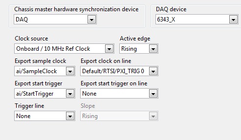
In the system definition file, under chassis, there is a setting for Master Unit of synchro material. Docs VS portrayed thus:
***************************
Setting a hardware Master chassis synchronization device
A chassis control hardware device controls synchronization the synchronization of all of the material in a frame and must be a NOR-DAQ device with at least one analog input or output channel, FPGAS OR or a timing and synchronization device that has the ability to lead the line 0. The RTSI 0 line is a digital line that send a clock signal that synchronizes all of the hardware I/O devices in the system.
Follow these steps to define a NOR-DAQ device like the chassis master device synchronization.
**************************
In General, what is needed to use the DAQ hardware to do a harware Sync? From > 1 card is used? What is the RTSI lines are used transparently to both the PCL and DIOs?
More precisely:
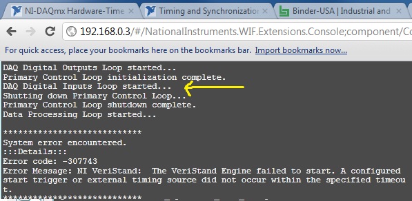
I got the following error at the time of deployment instance: error-307743:
We can see that something is going wrong with loop DI DAQ is started.
This error does not occur, and I deployed this file 10s and 10s times without problem.
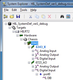
My system has 2 cards:
-PCIe 6343
-PCI 6723
The first thing I did to remove the DI of the 6723, the system very well deployed once, then the error came back
Finally, I watched the sync settings. They are defined as follows:
Their definition to None, working deployment. Then I put them back to DAQ, as on the fine above and all worked again.
Dig a little deeper in the present, I have noticed that if export sample clock is set to ao/sample clock error is back, despite the presence of strings in the AO list...
Been to you tips or file error system definition corrpution regarding these settings next to the info, that found the docs VS?
THX.
Laurent
You will have unexpected behavior if you are using hardware PCI and not connecting equipment with a cable RTSI.
The clock of the master device is designated with blue "BOLD", as shown on your screen. This device, as shown in the aid, which must be one that has at least 1 HAVE or AO. This device must then send the material sample clock to other analog devices (analog only!) in the system. This means that if you have other devices in your system that uses of HAVE or AO (and do not have the box 'disable the material unique point timed' checked)... they will expect to see an example of clock on PXI trigger 0 or RTSI 0.
If you use PXI... the sample clock is exported by the master on trigger PXI 0 and everything in the same backplane bus segment will see this automatically. If you use PCI... then you must either disable the hardware timing (not recommended) or acquire a RTSI-OR cable and follow this procedure that I just wrote to a colleague. (Ideally, we need to put this in the help in the future)
- Select the chassis page and designate (your multifunction data acquisition device) as the master of the chassis.
- In MAX, find your remote system, expand devices and interfaces
- Click with the right button on the chassis, then select identify-> external PC
- A right-click devices and interfaces and select Create new
- Choose cable RTSI-NOR and click on finish
- Right-click on the new cable RTSI-OR and add RTSI cable analog devices. These devices are necessary because they are the only devices with AI or AO is timed material (However some Councils don't support material as timing the 6704... which I do not recommend the use)
- Physically install a RTSI-OR cable between devices
-
The PXI-4461 connections and text based programming
Hello
I looking for a guide-schedule based on text for the PCI card, / AO PXI-4461 24 bit. Currently, I am able to program it similar to the PXI-6259 but could not find a way to set it up as (differential, Pseudo-differentiel) in order to obtain the correct output impedance.
Is there a hardware (user) for PXI-4461 guide?
I use Visual c# to encode the PXI-4461. How can I determine the location of the classes and the specific methods for the PXI-4461.
Thank you.
Anand
-
timed equipment digital input with usb port and windows
Hello
I have a data bus 16-bit I read in a computer windows laptop. There is a strobe data to tell me when to read the data I want. The STROBE will remain high for 1 time of speech to 10 Mbps (about 1 microsecond) the flow rate is much lower than the speed of the bus. I looked into the usb-6501 but it does not support hardware timing and mark will not work at this speed. Is there a usb device that will do it? Maybe a pc card? FireWire?
Please don't send me to pages on device selection. I looked and I couldn't find what I think I want to.
Thank you
Charlie
Hi Charlie,
The sampling rate overall max for USB form factor is 1 ms/s or 1.25MS / s for a single channel. The box USB-6251 takes in a 16-bit input. For higher sampling rates, you will need to use a PCI or PXI form factor.
-
PXI-4461 generate voltage update
Hello
When you try to run the sample Daqmx VI "Gen - Update.vi of tension" with an NI PXI-4461, I get the following error:
200758 error:
"Type of sample Timing is set to on demand that is not supported for analog output on this unit"
What does that mean?
Is there another way to generate a constant DC signal with the 4461?
Also - for next time that consider us to buy a new card - where can I get information on DAQmx properties (like this one) are supported for each camera?
Thank you
Ran
Hi Ran,
The 4461 NOR supports HAVE no single-point / AO of because it is based on delta-sigma converters a/n/CED, which require a clock free run at a constant speed.
There are two ways to output a signal DC with an NI 4461 (or NI 4431):
- Continuously to generate a waveform to DC (containing several repeated values).
- Set channels DAQmx > AO. IdleOutputBehavior to "Maintain the existing value" can generate several updates.
The help of LabVIEW has a page of "properties of the NI PXI-4461 supported", but it does list all the supported values for each property for each device. NOR-DAQmx help has a page entitled "Considerations for DSA timing devices" that talks on this subject:
"
Considerations of timetable for DSA devices
Supported sampling frequencies
Unlike some other devices DAQmx, DSA devices have a maximum and a minimum sampling frequency. Check your device specifications determine the range of sampling frequency.
Other considerations of DSA calendar
DSA devices do not support the type of synchronization on demand. All acquisitions of DSA and generations require hardware timing of a stable clock.
DSA devices do not support external synchronization sources of arbitrary external signals such as tachometers and encoders. PFI lines on the DSA hardware can accept external clocks. You can program a DSA device to use an external clock only when it is a slave in several synchronized system device. Refer to synchronization of the DSA for more details.
"
Brad
-
RT PXI, ethernet data transfer
I have a simple question, I just have to transfer data from my RT PXI system and get to my PC. That's all - I used the following code. Just by using this code, 50% of the resources are taken. Then I used shared variables to transfer dynamic data fromt channels (another question mark? if I have to do this) the system gives jittering... the trasfer is falling apart... After using 3 shared variables (published network) the system loses contact with the PXI as 100% CPU power is used in place... What is this RT PXI system? Need help
Controller on-board OR-8184
PXI.6259 M Series multifunction data acquisition
850 Mhz processor
256 MB OF RAM
Host PC: windows XP
just want to transfer the data, why is it so hard?
I have also used method TCP IP... an exaple... can not transfer more than one channel... can someone send me or tell me what is the best method... want to see is the unit I tested is what gives an output or not go to a remote place... in the same network... at least in the same room and it connected directly to my PC now.
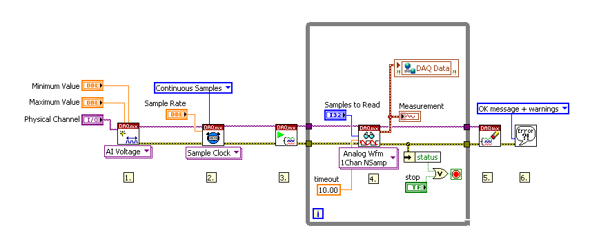
Hi mbhatti2000,
as I told you before: it's not maky any sense by using a loop timed in this example!
Use a non timed loop instead, the timing will be done implicitly by the acquisition rate and configure the samples to read you.
Before you start programming you become familiar with the principles of database aquisiton and real-time programming, you will find some useful links at the bottom of this thread. Have also a look at the examples that come with LabVIEW, there are also many examples to be found online.
The screenshot below shows you a very basic example of continuous data acquisition where a shared variable is used to transfer data to the host.
Also I would ask you to post your real code, as the screenshots do provide all of the necessary information.
Tutorial of Acquisition of comprehensive data
http://zone.NI.com/DevZone/CDA/tut/p/ID/3116
Training Module time LabVIEW Real-time
http://zone.NI.com/DevZone/CDA/tut/p/ID/9988
Kind regards
Bernd
Maybe you are looking for
-
I would turn off the Yahoo toolbar; but can't figure out how.
I have loaded down the latest version of Firefox, and now I have an AOL and Yahoo toolbar. I want to disable Yahoo; but can't figure out how. Thank you.
-
HP Compaq Small Form Factor DC: DC7800 graphic drivers
I have a new\second hand hard drive (320GB) and I had to reformat the hard drive of 74 GB. In the instructions given to me when I first bought the computer - after formatting the drive, I was instructed to download a graphic driver for DC7800 and yet
-
D110: Center of Solution program will not be installed with full features D110 download
I had a bug where my system kept looking up SolutionCenter.msi in a loop. I had to uninstall my printer completely software to fix it. After the relocation, the Solution Center is completely missing. I lost the CD and downloaded the software from thi
-
Hi, I have a Compaq Presario C700 no problems so far. It will not start when I turn it on the screen with criss cross lines and then a vertical black line, it turns black and then that's all. ? If I turn on and off for a couple of hours it starts? Ca
-
I have a program that I regularly build exe from code. In recent weeks, I've seen growing errors during construction. Before a backup solves the problem. The compiler complains about the error 1 for a random vi. The file identified changes and no