Hardware timed interruption
Where can I find sample code for an interruption of TMR/CTR channel so I can create a material interruption timed?
ex. clock frequency = 1 MHz. Period of loop = 100ms.
1. start the meter.
2 trigger interrupt when the counter = 10000.
3 reset the counter.
4 run the code interruption.
5. Repeat steps 2 to 5.
Thank you!
Tags: NI Software
Similar Questions
-
Hardware timed CI/CO, operation of PCI, I / AO with specific execution order
Hi all
I work with a USB-6361 NI data acquisition hardware and I'm writing a LabView 2011 program which sends a signal to my output device and reads several values of various measuring devices. I have a ramp voltage signal (in a table format) and I need to sequentially send the elements of this array on my AO device with very precise timing (ideally timed material). As soon as the value is written to the device of the AO, I need my tasks HERE and CI to record all available data and my task to send a single impulse before the next array element is sent to the device AO. All this needs very precisely timed such that if I perform a measurement on 1000 points in my table of ramp with a timing of 1000 Hz, the program will have exactly 1 sec. to run (less overloading caused in initialization and closing tasks) and produce a table of data consisting of 1000 steps of AI and CI. I had initially tried to achieve this by using a structure of sequence within a timed loop software, but because I won't get into multiple channels of Amnesty International and CI and tables of data, this has proved to be excessively slow. The other danger that I fear I could run is the case in which the LabView program runs more slowly than the process of acquisition data itself, thus causing data to write to the buffer and the measures being lost.
I didn't spend a lot of time working with the procedures, timing and synchronization, so I apologize if this is a rather naïve question - I'm having trouble reconciling restrict them inherent software and order of execution with the hardware timing. What is the best way to solve this problem? I can only think of two reasonable approaches to the problem:
(1) should I try to trigger my CI tasks and HAVE run on the completion of the task of the AO (and if so, how)?
(2) I have the CI and tasks run on a separate clock with a start delay initial light as to compensate for these tasks if they occur reliable after that each value AO is sent to my device?
Finally, I build an identical for a real-time embedded controller program of SMU-8100. The approach will be different in this case?
Thanks in advance for your answer.
I can give you an overview of the steps you'll need, but be ready to spend experiment a little time and some of these individual pieces of troubleshooting before you put them all together.
First of all, a X-series 63xx allows all you need to accomplish a very precise synchronization in hardware. When you then switch to a real-time controller, you must include an X-series device in the chassis to maintain this capacity of equipment.
Second, 1 kHz is not yet a challenge to LabVIEW to catch up with your hardware, even with powered lower RT controller. You just need to program the DAQmx tasks to let the hardware & driver do most of the work.
1. I would dedicate a counter of the 6361 to generate the clock shared for other DAQmx tasks. I tend to create a clock and operating cycle of 90-95% for this type of application of stimulus / response to the response time & maximum stabilization. Generate the stimulus at the cutting edge of the clock and gain response data on the edge of leak - before the next sample of stimulus. Call it the task of the clock.
2 set up a buffered AO task that uses the output of clock as the sample clock. Configure the polarity to be sensitive to the cutting edge (usually, this will be a rising edge). Start the task AO * before * starting the task of the clock.
3 configure tasks HERE and CI to use the output of clock as their clocks in the sample. Configure the polarity to be sensitive at the trailing edge. Start tasks I and CI * before * starting the task of the clock.
4. the output pulse should be a task of meter output, configured to generate a single pulse redeclenchables. Configure it to use the leading edge of the clock as the trigger signal output. Set the time of 'low' and the 'initial period' to equal precision<1 msec="" delay="" you="" want="" to="" make="" sure="" that="" you="" get="" the="" same="" timing="" on="" every="" trigger.="" be="" sure="" the="" high="" time="" allows="" the="" full="" pulse="" to="" fit="" within your="" clock="">
5 examine the "producer-consumer" model so that you can separate your data from your CQI data processing. You should stream to file continuous rather than it accumulates in large networks. Write speed of file can be unpredictable, this is why access to the file must be in a separate loop that acts as a data consumer that the loop of CQI data produced. When you spend real time, assign a lower priority in the process of writing file.
-Kevin P
-
I'm having a problem of selection of a clock for the PXI-6259. I've seen several posts on the forum on this issue, but the solution seems to be "read the manual"; I am not able to total, try it.
I have a chassis with an analogue 6723 static on the map and a 6259 multifunction data acquisition. I provide 4 sets of 2 digital inputs: a guideline and a pulse line. The user selects a number of impulses, a pulse width, and a destination for the pulse train. I use the number of pulses and pulse width to set up a digital waveform clocked. I can write the direction static c on the 6723 and the train of pulses at the timed HW DO on the 6259.
My problem is to select a clock for the pulse train. I tried using the sample AO clock and the sample clock HAVE to give me the ability to adjust the pulsewidth. I add the additional sample for the "wait until what Done.vi", but it times out when one of these clocks are used. If I use the time base of 100 kHz, the vi works well - but only for a 10us impulse. With the help of the time base destroyed my ability to change the pulse width.
I have attached the screw below; He let me just tie three.
The vi parent - control Tach, Full.vi
The creation of impulse vi tasks - create Pulse Channels.vi
The output vi - generate Tach Pulse.vi
The RWA selector is a typedef that selects one of the four outputs to send the train direction of signal and pulse to.
The typedef of Direction is converted to a Boolean value to write to the direction of entry.
I first create an array of tasks for the static DO the map of 6723, a special track.
Then, I create an array of tasks for the pulse on the map of 6259, including the establishment of the clock. I do this by taking the desired number of pulses, doubling (each pulse takes two samples), then adding one to allow the impulse to settle. I also add another sample, in addition to that for the vi "wait until what". This is the vi where to select which one to use.
I then choose the task of a pulse and direction, enter the values in the buffer and start explicitly jobs. After that wait until done return, I stop the tasks.
Waiting until it times out (I used up to 10 s) am the AO or sample clock is used. If I remove the wait until done, I get a warning (task may have stopped before all the written samples) with no output pulse train. It works very well with a time base of 100 kHz, but of course its fixed and cannot make any other sample rate other than 100 kHz/10us.
I have three questions:
1. the main problem - what I'm doing wrong with the clocks?
2. I put the program in time loop to allow the sending of one of the 4 outputs. I can send reverse or forward impulses out even any number of times, but the VI produces an error if I try to switch to another output (turned off, so I don't have the exact error code; it tells me that the task is reserved).
3. is it necessary to replace the task in the table when I'm done with it (for example, replace the code table subset)? What is exactly included in the thread of the task?
Had some extended time for testing today, and I found a solution. It is much more complicated as the example shows, although it seems obvious, once I write it.
It takes two tasks and two knots of timing to accomplish the digital generation timed by material:
A single task and node of synchronization for the digital task, I had put in place already
A single task and calendar for an analog task node allow the sample clock. I needed an analog task with a channel not used AND a timing node. Analog synchronization node should have the same sample rate and the number of samples that the node digital synchronization, but the source entry should be left blank to use the default clock (sample clock HAVE for a fictitious analog input channel).
Sailing smooth after that. Thanks for the help and insight!
-Nick
-
In the system definition file, under chassis, there is a setting for Master Unit of synchro material. Docs VS portrayed thus:
***************************
Setting a hardware Master chassis synchronization device
A chassis control hardware device controls synchronization the synchronization of all of the material in a frame and must be a NOR-DAQ device with at least one analog input or output channel, FPGAS OR or a timing and synchronization device that has the ability to lead the line 0. The RTSI 0 line is a digital line that send a clock signal that synchronizes all of the hardware I/O devices in the system.
Follow these steps to define a NOR-DAQ device like the chassis master device synchronization.
**************************
In General, what is needed to use the DAQ hardware to do a harware Sync? From > 1 card is used? What is the RTSI lines are used transparently to both the PCL and DIOs?
More precisely:
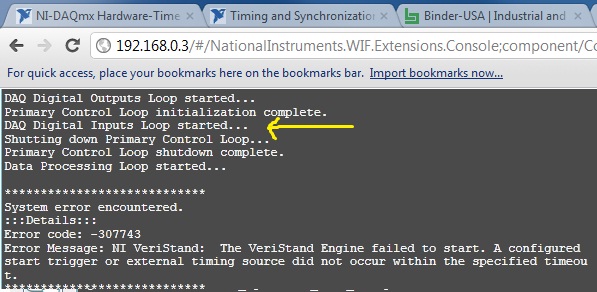
I got the following error at the time of deployment instance: error-307743:
We can see that something is going wrong with loop DI DAQ is started.
This error does not occur, and I deployed this file 10s and 10s times without problem.
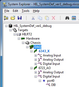
My system has 2 cards:
-PCIe 6343
-PCI 6723
The first thing I did to remove the DI of the 6723, the system very well deployed once, then the error came back
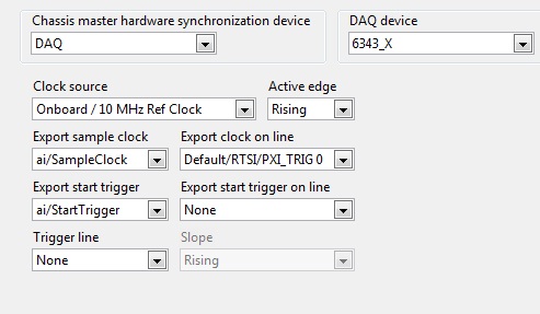
Finally, I watched the sync settings. They are defined as follows:
Their definition to None, working deployment. Then I put them back to DAQ, as on the fine above and all worked again.
Dig a little deeper in the present, I have noticed that if export sample clock is set to ao/sample clock error is back, despite the presence of strings in the AO list...
Been to you tips or file error system definition corrpution regarding these settings next to the info, that found the docs VS?
THX.
Laurent
You will have unexpected behavior if you are using hardware PCI and not connecting equipment with a cable RTSI.
The clock of the master device is designated with blue "BOLD", as shown on your screen. This device, as shown in the aid, which must be one that has at least 1 HAVE or AO. This device must then send the material sample clock to other analog devices (analog only!) in the system. This means that if you have other devices in your system that uses of HAVE or AO (and do not have the box 'disable the material unique point timed' checked)... they will expect to see an example of clock on PXI trigger 0 or RTSI 0.
If you use PXI... the sample clock is exported by the master on trigger PXI 0 and everything in the same backplane bus segment will see this automatically. If you use PCI... then you must either disable the hardware timing (not recommended) or acquire a RTSI-OR cable and follow this procedure that I just wrote to a colleague. (Ideally, we need to put this in the help in the future)
- Select the chassis page and designate (your multifunction data acquisition device) as the master of the chassis.
- In MAX, find your remote system, expand devices and interfaces
- Click with the right button on the chassis, then select identify-> external PC
- A right-click devices and interfaces and select Create new
- Choose cable RTSI-NOR and click on finish
- Right-click on the new cable RTSI-OR and add RTSI cable analog devices. These devices are necessary because they are the only devices with AI or AO is timed material (However some Councils don't support material as timing the 6704... which I do not recommend the use)
- Physically install a RTSI-OR cable between devices
-
USB-6212: software problem timed task of analog input
Hi all
I have unexpected behavior using a USB-6212.
The code example shows that when I run in sequence two analog DAQmx to task, material entry first a timed, the second software timed, it happens that the first readings of data are all wrong and have the same value for all channels.
The labour code is the following:
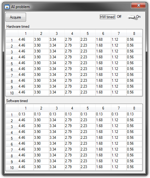
   GetCtrlVal(panelHandle, PANEL_HW, &Switch);

    if (Switch) {
//
// First Task: read 10 rows of values with hardware timing
//
        DAQmxCreateTask("", &htAI);
        DAQmxCreateAIVoltageChan (htAI, MX_DEV_AI, "", DAQmx_Val_NRSE, -10.0, 10.0, DAQmx_Val_Volts, "");
        DAQmxCfgSampClkTiming(htAI,"", SAMPLE_RATE, DAQmx_Val_Rising, DAQmx_Val_ContSamps, 1000);
        DAQmxRegisterEveryNSamplesEvent (htAI, DAQmx_Val_Acquired_Into_Buffer, SAMPLE_RATE, 0, RefreshCB, NULL);
        DAQmxStartTask(htAI);
            Delay(1.0);

        DAQmxStopTask(htAI);
        DAQmxClearTask(htAI);
    }
//
// Second Task:read 10 rows of values with software timing
//
    DAQmxCreateTask("", &htAI);
        DAQmxCreateAIVoltageChan(htAI, MX_DEV_AI, "", DAQmx_Val_NRSE, -10.0, 10.0, DAQmx_Val_Volts, "");
        DAQmxStartTask(htAI);

    for (i=1; i<=10; i++) {
        DAQmxReadAnalogF64(htAI, 1.0, 10.0, DAQmx_Val_GroupByChannel, AcqVoltRow, HW_AI_CHANNELS, &read, 0);
        SetTableCellRangeVals (panelHandle,PANEL_SOFT, MakeRect(i, 1, 1, HW_AI_CHANNELS), AcqVoltRow, VAL_ROW_MAJOR);
        Delay(0.1);
    }
    DAQmxStopTask(htAI);
    DAQmxClearTask(htAI);
A picture is worth a thousand words: analog inputs have been connected to a network of resistance have known values.
The upper table contains timed material acquisitions, the lower the software timed readings... as you can see it the first line is the set of values of 0.13, totally wrong
If the task of timed acquisition of software runs without the earlier (in my demo, that this can be achieved by the switch at the top right), the readings are correct!
Y at - it something I am doing wrong?
I also tried to run the program on USB-6009, but it seems to work properly.
[LabWindows/CVI 2010 SP1 - driver OR-DAQmx 9.4 - Windows 7 x 64]
This problem was corrected by NOR-DAQmx 9.5
324044 NOR USB-621 x task HAVE request returns incorrect data after erasing a task HAVE stamped
-
Digital IO ports on PXI-6025E support material timing?
I need to use digital lines for tasks with calendar clock requiring hardware timing sample.
PXI-6025E has this ability?
If so, each independently configurable port with different sample at the same time clock timings?
If this is not the case, what camera would be a good alternative with configurable ports separately?
The PXI-6259 supports digital hardware timing. It worked only on port 0 because that's how M-Series are designed. As long as you have enough digital channels on port 0 for your application, this device should work. Also, here is an article on how to find the specification that you are curious about.
http://digital.NI.com/public.nsf/allkb/08F477754D0535CE862570020007142C?OpenDocument
Kind regards
Isaac S.
-
Properties of the NOR-XNET CAN frame timing type
Hi all
I have a problem of timing of the CAN. I start to read / write CAN bus every 10ms. I am using loops timed for this and I usually see 9ms / 10ms loop intervals of itteration, that's fine. However, sometimes my comms CAN down completely and that the loop can take 5 seconds to turns off once. The work rate of the cpu (from the Task Manager) does not seem too badly loaded)<>
I noticed in the editor of database of NOR-XNET, I have the choice of the type of calendar. I am currently using the event data, but I was wondering if there was something I could do to use some kind of hardware timing for my transmissions CAN? Curiously, neither aid seems fairly limited for the calendar type (where my post here). Any help on what means the type of calendar options, and if a is likely to strengthen my time 10ms loop and (hopefully) stop my bus CAN lock up risks would be apprciated.
Thank you very much.
georgeofthejungle wrote:
I use 'Framework in single point' for my readings and 'Unique exit point' for my writing.
I chose the type of cyclic calendar with a time limit for the transmission of 10ms in my NOR-XNET database. It seems to be better now, - I haven't seen 1 instance of my may lock up repeatedly. I still have my loop timed to 10ms containing my NOR-XNET write VI.
I'm not using a queued session, - if I understand correctly, the queue will hold managers and they will be released sequentially at intervals of 10 ms? The only point & cyclic timing so I understand that if a new image is written so the same frame will be published every 10ms. - it fits my needs for now.
After reading the help, point one looks like it will work enough for you. Keep in mind that if you finish writing twice before the next transmission 10 ms, you can miss an update signal. This can happen if your software update of 10ms is not quite of the transmission of material 10 ms.
With the type of cyclic calendar and Frame in single point, are my transmissions CAN timed material now? -They seem more regularly now and I have not had a case of the loop CAN lock up.
The cyclical schedule will force the transmissions timed HW of the controller CAN then Yes, you're now HW timed for transmission.
Thanks again for your help.
I'm glad that your CAN bus seems to be much happier now. Feel free to post if you have something else.
-
timed equipment digital input with usb port and windows
Hello
I have a data bus 16-bit I read in a computer windows laptop. There is a strobe data to tell me when to read the data I want. The STROBE will remain high for 1 time of speech to 10 Mbps (about 1 microsecond) the flow rate is much lower than the speed of the bus. I looked into the usb-6501 but it does not support hardware timing and mark will not work at this speed. Is there a usb device that will do it? Maybe a pc card? FireWire?
Please don't send me to pages on device selection. I looked and I couldn't find what I think I want to.
Thank you
Charlie
Hi Charlie,
The sampling rate overall max for USB form factor is 1 ms/s or 1.25MS / s for a single channel. The box USB-6251 takes in a 16-bit input. For higher sampling rates, you will need to use a PCI or PXI form factor.
-
Timed software a generation of impulses - USB-6009
Hello.
I searched for a reliable way to produce a pulse point by point with the USB-6009. My question is whether or not it is possible to produce such a signal without hardware timing or a counter as the USB-6009 supports neither. Is the closest I've come to produce a square with a very low duty cycle wave. However, what I would ideally look for is the ability to produce a single pulse inside a loop which I can go once per minute or more. Also, I would like to know what are the parameters I would be sacrificing to produce a pulse in this way.
I also have access to a function generator and as it seems quite difficult I will be probably triggering just its pulse function in the same way, but I'd like to explore this obstacle before moving on.
Thank you
Travis.
20 ms can enter the region where you will begin to see significant amounts of timing jitter. You really need to write your program and make some careful measurements - over a long period of time - to see how much of a problem you will have. Actual performance will depend on a lot of details: the operating system, other software process running in the background, and how the LV program is implemented. You must reduce as much as possible, everything else on the computer: no network, no antivirus, no Bluetooth or WiFi connection and so on...
Lynn
-
difference in the hardware and software calendar
Hello world.
I have a few questions about the time of hardware and software.
1. What is the difference between hardware and software?
2. What does hardware mean? PC or DAQ as usb 6211?
3 when I use "DAQmx Timer", it means that I use the hardware timing?
Thanks for your help!
Hi Xiang00,
>> 1. What is the difference between hardware and software?
Hardware timing is more accurate, because it uses the on-board clock. Avoiding the is less precise because it depends on the performance of the PC.
>> 2. What does hardware mean? PC or DAQ as usb 6211?
"Hardware" means the hardware such as USB-6211 DAQ.
>. 3. when I use "DAQmx Timer", does this mean that I use the hardware timing?
Yes. You can find more information in the knowledge base DAQmx Timing and sampling frequencies.
Best regards
Yusuke Minami
Sales engineer, OR the Japan
-
AO. MaxRate, AO. MinRate, AO. Properties of voltage. RNGs for hardware DAQ USB-6008
Hello
in one of my report, I use the AO. Property of Voltage.Rngs to see if the selected DAQ card takes in charge the application voltage range. This works very well for my PCMCIA card as well as a PCI card. Now run the same VI with a USB-6008 device, this property gives all the return values. In addition, the report of AO.max.rate and AO.min.rate of the '0', the output is-200197 error properties. I use DAQmx as it is supposed to support the same functions for all DAQmx devices. Can someone please tell me what wrong here and how can I get around this?
Best regards
Gabs
AO.min.rate and AO.max.rate are 0 and error-200197 back because the USB-6008 case supports the outputs analog hardware timed. The description of error is "device does not support this property." There is an entrance to the knowledge base for this question.
By selecting 'Use Waveform' uses the synchronization of the sample clock. The waveform data type specifies a delta t, which is used to set the sample clock frequency. It is not supported on the box USB-6008. You shouldn't set your calendar of sample type or explicitly assign the "On Demand".
The DAQmx driver supports hundreds of different devices. Not all combinations of properties are valid for all devices.
-
DaqMX wait the next sample causing slow down Clock.vi
Hello
I have a question about the proper use of DaqMX wait for next sample clock.
I read channels analog voltage on a map or pcie-6259.
I would like to read as soon as possible make your comments between each of these points of single data points.
I wish I had an error generated if I miss a data point.
From reading the forums, I've gathered that the best way to do it is using the Timed Single Point material.
A simplified program that I use to test this is attached.
If I remove the DaqMX wait for next sample Clock.vi, my program seems to work.
I added a counter to check the total time is as expected.
For example, the program seems to work at the speed appropriate for 120.
However, without that vi, it seems that the program does not generate a warning if I missed a sample.
So I thought that the next sample clock waiting vi could be used to determine if a single data point has been missed using the output "is late."
However, when I add inside as shown in the joint, the program seems to slow down considerably.
At high rates as 120000, I get the error:-209802
14kHz is the approximate maximum rate before you start to make mistakes.
My question is: is this the right way to check a missed sample? I don't understand why the wait next sample Clock.vi is originally a slow down. Without this vi, the program does just what I want except that I do not have strict error control.
My confusion may be based on a lack of understanding of real-time systems. I don't think I do 'real time' as I run on an ordinary pc, so maybe I use some features that I wouldn't.
Thank you
Mike
Mike,
You should be able to read to return delays errors and warnings by setting the DAQmx real-time-> ReportMissedSamp property. I think that if you enable this, you will see errors or warnings (according to the DAQmx real-time-> ConvertLateErrorsToWarnings) in the case where you use read-only. I'm a little surprised that you have measured your application works at 120 kHz without waiting for next sample clock (WFNSC), although I'm not surprised that it would be significantly faster. I think if you call read-only, you'll read the last sample available regardless of whether you would of missed samples or not. When you call WFNSC, DAQmx will always wait for the next, if you are late or not sample clock. In this case, you will wait an additional sample clock that is not the case in read-only. Once again, I expect that, in both cases, your loop would not go to 120 kHz.
Features real-time DAQmx (hardware Timed Single Point - HWTSP) are a set of features that are optimized for a one-time operation, but also a mechanism to provide feedback as to if a request is following the acquisition. There is nothing inherently wrong with using this feature on a non real-time OS. However, planner of a non real-time OS is not going to be deterministic. This means that your app 'real time' may be interrupted for a period not confined while the BONE died in the service of other applications or everything he needs to do. DAQmx will always tell you if your application is to follow, but can do nothing to guarantee that this will happen. Thus, your request * must * tolerant bet of this type of interruption.
There are a few things to consider. If it is important that you perform the action at a given rate, then you should consider using a real-time operating system, or even with an FPGA based approach. If it is not essential to your system, you might consider using is HWTSP, where you do not declare lack samples (DAQmx simply give you the most recent example), or you could avoid HW timing all together and just use HAVE request to acquire a sample at a time. What is appropriate depends on the requirements of your application.
Hope that helps,
Dan
-
The page "What's new" is displayed after update 35.0.1 36 is broken - no buttons can be clicked. A carefully timed interrupted page refresh gives me what I suppose is the expected result. Remove '? OldVersion = 35.0.1"URI also unbreaks page.
Hi Jens_Lyn_IV, it is probably caused by the extension of the TRC. What would normally happen is a panel of doorhanger appearing under the menu button, offering to do a tour through the new features of the version...
-
read the multiple analog inputs at the same time
Hi all
I use USB-6001 and want to develop an application to multiple tasks in C++. I try to read several analog inputs at the same time, but got some errors. To put it simply, I copy one of the sample code to read in analog data in a channel, and then turn it into function. Then I call this function to thread with the names of different poles (for example Dev1/ai0, Dev1/ai1) and I come across this error:
"The specified source is reserved. The operation can not be specified such complete"code of State-50103
I have search the forums, this may be because I use the hardware timing in this function, and this material timing cannot be used simultaneously by multiple tasks. I may have to put all the lines, I want to read in a single task (such as Dev1 / ai0:1). This way I can read two lines at the same time. However, when I try this, I encounter another error:
Status code "buffer is too small to contain the data read" - 200299
So here is my question, what should I do if I don't want to read the multiple analog inputs at the same time? Is the thing that hard time cannot be used by several true task? If I have to read several lines to a single task, how to set the settings?
-
Problem with DAQmx Schedule VI (sample clock)
Hello to you all,.
I'm new to this forum, please bare with me. I have some experience with LV, but I am relatively new to data acquisition projects. I use LV2009.
I want to make sure that I use the hardware timing (instead of software distribution) in my project so I followed some of the threads here as sugested to use DAQmx Schedule VI. The problem is that no matter how I set the system I get the same error-200300 invalid calendar
type.The project is simple. I encode with 1000 pulses per
Rev and it is mounted on a shaft of a turbine water goes thru. I'm watching the frequency
and so the rotation of the shaft which tells me that the amount of water flows through the turbine. In the end, there will be 2 channels
by every encoder and ~ 3 encoders (turbines) total and calibrated the main meter that will give me constant impulses and all encoders will be compared to this master frequency.I'll use PCI6602 DAQ, but
now, for the development, I use USB6221. Let's say that the
frequency is between 500 Hz and 10 kHz. What I am doing wrong? Or maybe better to ask - what would be the right approach for this project?Thank you
Marty
Hi Marty,
It seems that your question is already answered here, but Jason is correct that the 6221 neither the 6602 support a clock sampling for frequency measurements.
As Jason mentioned, your best bet is also likely set the mode of synchronization for "implied". This means that the frequency value is sampled at the end of each period of your input signal. In addition, a solution that is clocked by the software (On-Demand) might be acceptable.
X Series DAQ devices allow an external sample clock to use for frequency measures (described in the Manual of X series). Frequency of sample-clocked measures are useful in very specific
circumstances, but it does not seem that you need this feature based on what you've described so far.(621 x) bus-powered M series can also be configured to use an external sample as the X series clock but do you not have the same features described in the manual of the X series.
I hope this helps!
-John
Maybe you are looking for
-
Webcam starts to turn himself.
my webcam starts to turn himself.somebody's watching me?I could not find any virus or Trojan horse.
-
Problems with Toshiba Flash cards
I have problems with toshiba flash Cards on my desk and stay there. It says flash cards, not reponding, but I can't get rid of it. This utility is really necessary to make my computer work correctly? How can I get it out of my office?
-
Cannot find the operating system at startup
Using my Vista PC, I installed XP-Pro(32bit) disk a HARD tour, (which HARD drive has been correctly removed from the target computer), but now my Vista PC can not find any OS. (I HOPE a different permutation - thanks.)
-
Hi allOracle version 11.2.0.2 XE edition, OEL 5.6I am facing error during the creation of tablespace that my system tablespace is full. Although the system tablespace is autoextend and there is space available on the hard disk what preventing the sys
-
Error al add storage (datastore) en virtualcenter
Buenos diasTenemos una infrastructure of various host esx 3.5 gestionados por un virtualcenter 2.5 desde hace varios Años. Desde hace unos Días me da UN error cuando intento add storage para crear a datastore para lo tengo are presented as nuevo has