generate a digital signal for 6722 or 6221
Hello
Thanks first for the help I'm already on this forum.
Now, I have the following problem:
I like to generate a digital signal: high for 300µs, low 300 µs, 300µs high, low 300µs, top for about 2 ms.
I'm looking for a solution how to generate this numerical sequence. At the same time, I will read the information via an analog input (if all goes well, I now have a solution for this problem).
I tried to find examples, but I failed. For the moment, I was not able to produce any numeric sequence that worked.
My hardware is 6722 or 6221 - which should be OK with respect to the calendar.
Thank you
Tags: NI Software
Similar Questions
-
generate the TTL signal for synchronization from another device with Labview
Hi all
I use NEITHER-6071E and try to generate and send a TTL signal so I can synchronize another device with my Labview code. My code (code attached) generates a sine wave, and I want to send a singal TTL out at an angle of phase on the sine wave. Currently, the code sends a sinusoidal signal and a square using similar wave output on BNC Plug. I thought I could just use a square wave, and send it out as analog output for the other device, but apprantly that he works with a TTL signal.
Could you please take a look at my code and advice me how to generate a TTL signal while being able to send it to some phase shift?
Thank you davance
Pooya
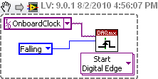
There is almost everything using examples > find examples... menu
but here is one which simply sends a single impulse:
Note that I expect the line have been pre-defined in MAX (it's always a good idea to check that your DIO line behaves as expected by trying it in MAX).
-
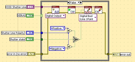
How to generate a digital signal on a negative slope of the clock?
Hello
I need to get out a finished length of the Digital pulse which will begin on request to the negative of the clock slope import (or export).
I try to get the clock, exported or imported, but in any case, I can trigger output signal on the negative slope.
What is the trick?
Thank you
Pawel
What camera you use to build your digital signal. What is the source of the clock? You can attach your vi? Normally, there is a function of data acquisition for configure the trigger where you choose the source of the trigger and the trigger slope (rising or falling), should be declining to a negative slope.
-
How to control each channel of the signals emitted by the generator of digital waveforms?
Generator has digital waveforms of 8 channels. I need to generate two different signals for HSDIO. How to change and control two different ways? In addition, how to translate pinout of the PXI-6541 to channels? I need pin 1,3,29 and 31 control signal individually.
Thank you!!
You need to combine your personal data in a table. The digital waveforms is simply a numeric representation of the binary table. It always boils down to bit 0 of each element of the array will channel 0 (or the first string that you specify in creating dynamic channels). The next bit goes to the next channel. My last post is very clear. To display the table in binary, right-click on a table element, then select the display Format, then select binary. You can also right click on the element, select Visible, then select Radix Show to display the small b before the number. One last thing, in the display Format window, uncheck the box next to the minimum field width to use. Then set the digital just below zone 8. Then select Pad with zeros to the left in the box below.
You should not use waveforms up to what learn you more about how the HSDIO operates on the input data. It is not difficult to combine waveforms, but it is not as clear as it is using an array of U8, U16 or U32.
Trying to explain further. The first number to be written to the HSDIO will have this effect: Bit 0 (LSB) of the number is written to the first HSDIO string you specify. Bit 7 is on channel 8, you specify. If you specify no 8 channels, the bits download ignored. If wiring in a certain number will produce only a single bit on each channel. In other words, the number has already combines the bits of all channels that you specify. Combine you do nothing yourself. Return to my photo on my last post. By wiring in a table, you cause a binary model must be generated.
I hope that is more clear.
-
2 digital signals keep using pxi 6544
Hello
I wonder how I can generate 2 digital signals that continues and I will able to make even phase, or different phase 1/2, or 1/4 different phases. And I need them to be able to their output in any channel (free) my PXI 6544.
I've seen examples of generation (no script), but most of the examples shows just how to generate data in parallel. Generating script I use to achieve this? Repeat for the thing?
Kind regards
Yan
-
MyDAQ - generation of a digital signal and display on an analog waveform graph
Hello
I use the MyDAQ OR generate a digital waveform with a Frequency adjustable. This is implemented in a program, I already wrote it, which generates a TTL 'like' impulse out of the sound card. I display the result on a graph of analog wave form, and I would like to be able to display the digital signals generated by the myDAQ on the same graph. (Not in the same time, one or the other, activated by a button). I've been messing around with tables and conversions, but I can't really do with all this.
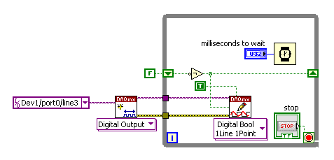
It's the vi, I did to generate the digital signal of frequency with MyDAQ. Any suggestions on how to do this if the following is false, would be great too, as I just got the MyDAQ a few days ago. I think there must be a better way, but it's the best I could come up with so far.
Hi Jonny,
The General logic, that you use to create a digital pulse train is very good. This VI you wrote should work and create the pulse train based on timing of software (which is fine because you have not DIO clocked by the material on the myDAQ anyway). However, it is generally advised to start the DAQmx task just before your time loop and then disable the task after the while loop when you press stop.
For reference, there are a few examples of good enough LV that I recommend you watch too much for this application. If you try just to create a digital pulse train, the example Gen dig Pulse Train - Continuous.vi is a good example that uses a counter to create a digital pulse of your desired frequency train. It is generally the preferred method to create a pulse train, if you have equipment available to do (the myDAQ there a meter). Otherwise, there are a few examples DIO who write continuously in a digital line / port.
If you are unfamiliar, you can find the examples by clicking Help > examples find... into LV then navigate to hardware input and output > DAQmx > generating digital impulses or the digital generation.
Also, here is some additional information on the myDAQ and its counters:
Hope this helps.
Chris G
-
frequency of the digital signal 6009
Hello, how to generate the digital signal with frequency 50 Hz using NI USB-6009?
You can take a look at this:
Can I use a generation of impulses with the counters on the USB-6008/6009 case?
-
Jitter in response to signal generator of digital dashboard by using trigger nor tclk with digitizer
I've written a VI that uses NEITHER tclk to synchronize a generator (PXI-5422 named FGEN1) and a digitizer (PXI-5122 named DIGITIZER1). There is also a clock card TIMING3 generating a digital camera.
It seems that can probably be explained by the way TCLK to synchronize, but I don't understand all the details. Could someone help explain this to me?
You are right. NOR-TClk ensures that all synchronized devices start at almost at the same time, to the same sample clock, with timing very tight. Sometimes, the level of synchronization with the devices OR TClk-synchronized beats at the level of the synchronization of the instruments of some competitor channels in the same device. But this is not free, there are compromises and added additional jitter for trigger response time is one of them. Here is an attempt to explain why:
When you use NEITHER-TClk and send a trigger, the devices will respond to relax on the next cycle of the clock once made the trigger signal to the device. Let's say you have several devices all of them even configured with the same clock frequency. You block the signal of PXI_Clk10 using their PLL, so they drift out. But each unit's clock edge will be off, clock +-0.5 cycles. If you send a trigger to each of them, they will respond on the next clock cycle whenever it is, after the arrival of the relaxation to each device with different propagation times, whatever they may be. You get a single clock cycle of jitter on reaction of device to set it off.
When you use NEITHER-TClk, several things happen: all devices are locked on the PXI_Clk10 signal to eliminate drift. The device clocks are then adjusted to a period level secondary clock. Very very tight. Then a clock signal common, slower called TClk is produced inside the devices. All the generation of trigger are delayed to be sent to the next rising edge TClk, and all consumption trigger is delayed to be received at the next front descending TClk. This way you make sure that propagation delays don't mean one of the devices does not react to the trigger until the next clock cycle.
That's why you see jitter above the reaction time of relaxation. When you add devices with different clock settings, so the frequency of the TClk can be slower for a divisible frequency in the device clock frequencies everything is possible. This causes the trigger jitter of reaction time be even slower!
I hope this helps you understand what you see.
-
generate a digital triggering out CH1 (low and high) for the USB-5133
Hello
I would like to generate a digital triggering on the USB 5133 CH1, is this possible? I tried with the PFI 1 successfully but the output is only 3.5 v and I need to 5V, because this trigger signal goes to a box of pulse generates a signal, which is received by the CH0 on the USB-5133. This configuration works on the 5102 OR but because of the treatment, I am obliged to try a new device.
Channel 0 and 1 are only entries then you will not be able to use them to generate a signal. All of our products current digitizer that are recommended for new designs use 3.3V CMOS logic levels for PFI lines in output mode. Your best bet to generate a digital triggering 5V would be to use an external buffer that can accept 3.3V CMOS levels as an input, but is under voltage of 5V. Here are some that might work for you, but there are many others: http://www.onsemi.com/PowerSolutions/product.do?id=M74VHC1GT126DT1G adding a buffer in line with the trigger signal will add delay, so you will need to ensure that it is acceptable for your application.
Hope this helps,
-Matt
-
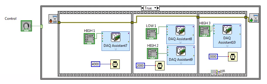
Is there a better way to generate the custom timed digital signals
I'm trying to generate the digital output from the top and down with delays on different lines. Each daq assistant is activate single line on a port USB 6501. There more complex high and lows that I need to generate variable time difference between high and low. There is codebelow that does what I'm trying to achieve, but for a model executing high and low signal is much of your time to do it this way. I'm sure there is a better way to do it, I'm not an expert on labview so I only discovered its potential. Anyone can suggest a more effective and a quick way to do it. I would like to hgihly appreciate. Thank you!
I've not shown in the code below, but using the DAQ assistant, I initialized lines at low logic level.
-
Generate the pulse signal signle on the digital output line
Hello
I am now writing a program using c# and DAQmx.
I have a NI PCI-6514card and I want to send a signal for half a second to a single line of output.
I know how to write online by using the DigitalSingleChannelWriter object, but I want this signal, disappear after a period of time.
Thanks in advance for your support.
J.. Gasser
One thing is certain:
C:\Users\Public\Documents\National Instruments\NI-DAQ\Examples\DotNET2.0\Counter\Generate Pulse\GenDigPulse\cs
It is on Vista.
On XP, I believe that the path is:
C:\Documents and Settings\All Users\National Instruments\...
-
Generate a digital output that indicates the frequency of half of the contribution
Hi, I'm new with data acquisition. I would like to get your help.
I have a digital signal input that is generated by an encoder. I would like to generate an output signal of the way that his level of signal will change at each edge of the awareness of the input signal so that the frequency is half that of the entry.
I would like to know how to do this using the NI DAQ M 6221 map.
Thanks for your help

Hardware solutions can be so simple... sometimes I prefer an iron solder wire

Look at the section counter...
I think there's a prescaler/separator for the meter... and the next would try to drive the output to a PFI
-
Best way to generate the software clock for USB-6501 of Measurement Studio for c# VS2008
Hi all
I wonder if there is a better way to generate a clock software for USB-6501 of Measurement Studio for VS2008 in C Sharp?
I have developed a clock using C Sharp "Thread.Sleep (msecPauseTime)"; and statements to switch digital output high and low. There are a few things I noticed in creating a software clock in this way:
- The smallest delay by the Thread.Sleep command time is 1 millisecond (which means higher clock period is 2 msec-500 Hz, not holding not ball account no. 2 below).
- Sometimes the delay I see on an oscilloscope is considerably longer than the delay that I specified in the sleep command.
In my application, I create signals (a clock, a latch enable and data series) to control what an attenuator step through the USB-6501 RF connected to a USB 2.0 on my computer. This particular step RF attenuator can accept clocks with frequencies up to 10 MHz, so I would like to generate a software clock (without having to connect to an external clock to a line of input on the USB-6501) which is closest to this maximum frequency, and I think that the USB2.0 line could handle clock speeds over 500 Hz. Also, I would like to know why the delays that I see on the scope are sometimes longer than the time specified by the Thread.Sleep command. Is it caused by the suspension of the execution of my program processor for something else, as I suspect? Of course, this isn't a big deal, because it does not affect the time as my serial data and pieces change compared to my clock. However, I would like to know why it does this.
I appreciate your help.
Thank you
Jonathan Becker
Doctoral research engineer
Carnegie Mellon Silicon Valley
Jonathan,
Since the USB-6501 DIO is software programmed, you are at the mercy of the planning of the operating system and won't be able to work reliably with an external clock in the software.
You can try to set the priority of your thread 'generation of clock' to improve performance, however, because Windows is not a deterministic operating system, there are still no guarantees. Operating systems are not required to honor the priority of threads. You can find examples and information on the definition of the priorities of the threads in c# here:
http://msdn.Microsoft.com/en-us/library/system.Threading.thread.priority.aspx
Kind regards
-
Generate a digital waveform like memory on PXI cards
Hello
I'm looking for a way to send a large digital waveforms using a PXI digital signal generator. I saw DIO HS cards, but their memory is smaller than the files that I want to transfer. My understanding is that the PXI backplane bandwidth 132 MB/s. So, I shouldn't be able to stream a digital signal from the memory of the card that is slower than the CPU? For example, 50 Mbits / second (equivalent to only 6.25 MB/s)? However, I think I understand after reading their textbooks is that you cannot continuously transmitting a large waveform of the processor memory file, you must transfer the file to the memory of Council first and then transfer that out.
Does anyone know if there is a way to have a flow of digital signal generation card an arbitrarily large directly from memory to the processor of digital signals? Or, what is the fastest card of pxi digital signal generation that does not require the storage of Council first files?
Thank you
Isaac
Hello Isaac,.
Take a look at the following area developer.
NOR-HSDIO Stream from disk (generation) using Win32 file IO
Note that you will not be able to take full advantage of the maximum rate of update HSDIO devices, because the data must be transferred in a bus. Some other considerations are the width of the data as well as the HSDIO device you select, which may depend on other requirements not related to the size of file or waveform (for example the standard voltage or whether you need hardware compare). For more information, take a look at the developer following items area.
Data streaming of Architectures in the PXI systems
The use of National Instruments Logic Analyzer and generator of test patterns SolutionAdvanced features of e/s high-speed digital devices White Paper Series
-
Generation of digital signals through external trigger pulse on PCI 6251
Sir I want by NI 6251 because I read it has the ability to generate and acquire digital signals on port 0. I want to know that can I generate external clock wave triggering (providing impulses to a line on the acquisition of data)?
Hi Ali211,
Yes, you can use a source of sample for the digital input/output clock external clock. You can connect the external clock source to one of the lines PFI (PFI0-PFI15) and specify the source clock sample like this outer line of PFI.
There are some shipping DAQmx examples that you can start with. Find the examples by clicking Help > find examples in LabVIEW.
DAQmx continually reading digital channel with External Clock
DAQmx channel External digital writing Clock
Hope this helps.
Chris G
Maybe you are looking for
-
After the last update of iOS10. Even though I am connected to iCloud when I try to display the content he asks me to implement the iCloud. Can anyone help please.
-
iTunes billed me and I have not bought anything, why am I being charged
iTunes billed me and I have not bought anything, why am I being charged
-
It is a 'new' system or Microsoft just put more lipstick on his old pig?
I'm sorry, but XP and Vista are both junk. Is it also going to have to have some updates daily as being safe and run? I have an older laptop that has a 1/3 of this memory tied up in some updates.
-
HP TouchSmart Ultrabook 4 ENVY: fried, drive will NOT boot from usb
Hard drive clicking on, definitely fried. Replaced by the new hard drive. No matter what I do, it will not start from the bootable USB key with windows 8 install on it. Stick to boots on other computers. I press ESC to the maximum power that I can g
-
For three buildings with VPN routing tables
Can someone tell me how to configure routing for the following tables I have three location. All three have a static public IP address I need to have a VPN to each location at each location A = 192.168.0.x B = 192.168.1.x C = 192.168.2.x There are v