How to generate a signal of persistent arousal in LabVIEW
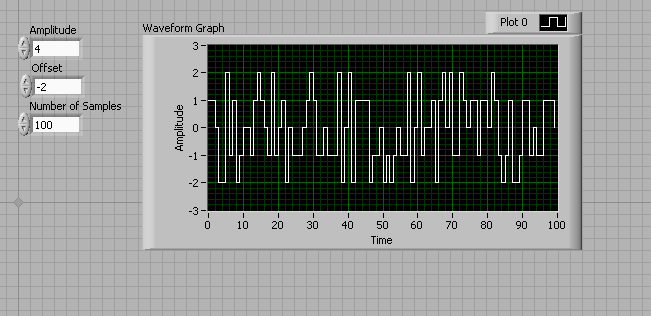
Please can someone please help on how I can develop a persistent exciting in LabVIEW for identification, resembling her attached attached document (filtered white Gaussian noise).
Hello
Do you mean something like this:
And the code for this:
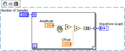
I hope this helps!
Tags: NI Software
Similar Questions
-
How to generate analog signals?
Hi all
I'm trying to generate analog signals to simulate the position of the valve. I also want to simulate the position of the valve 0 - 5V (analog signal). I've implemented the numeric position of the valve by using the toggle switches, but I want to implement analog signals.
You can help.
Thank you
You can just use a random number generator.
Since you have no generator hardware signals of NOR, I'm not sure why you are posting to this Board. Generic questions of LabVIEW. Post to this Board.
-
How to use generate multiple signals on a single DAQ Assistant
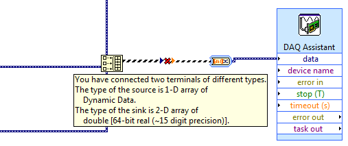
I am trying to generate several AO on my DAQ card, but I kept getting an error. I looked at the error and he said that I had to use a single DAQ Assistant. So, I created one, but I can't understand how to connect the signals. I get lines that don't connect. Is attached a picture of the installation. Thank you!!!
If you want to use the type of dynamic data, you must use the appropriate function. Do not use the construction. Use the Signal to merge. Then wire you the output of said directly to the Assistant.
-
How to pass a signal between 2 worksheets
I created a signal evaluation sheet and I want to transmit the signal that is to assess a separate spreadsheet that generates the signal. If I use the module generator frequency to generate the signal output so how a calculation sheet and read it as an input in the other worksheet?
Bill,
You can run only one sheet at a time.
How to transfer data from one sheet to the other would be to save the data in a file. DDF is the most flexible for writing and for DASYLab replay DASYLab.
Use of the files, data group of writing and reading data. The file must already exist to configure the module for reading data.
-
How to generate an impulse to test short circuit in an inducer
Hello
IM new to labview and am in need of complete SURG - SURGE STRESS TEST
This test is intended to detect a short tour inter by applying a number of high
voltage pulses (or surge) for the selected winding.
Each pulse should produce one sinusoidal transient that eventually decreases to zero.How to generate the impulse using labview.
Hi Jessica,.
Please see the "pulse pattern.vi" function--> pallets of signal processing signal generation.
Otherwise, you can browse through examples of LabVIEW.
Kind regards
Srikrishna.J
-
Generating the signal as shown in the picture in labview
Hello
I'm using labview in 2011 and want to generate the second signal as shown in the picture attached in labview as I want to use it as input to implement adaptive filtering, if the first signal in the image represents the output of the adaptive filtering area.
May I know how to generate a second signal.
Thank you.
-
Connection diagram missing in DAQ Assistant generate the signalling block
This is my first post so please excuse the quality of my description.
When I double click on the block of data acquisition - Assistant, there is no tab connection diagram I can access to see how things are wired to the top. I have a NI USB-6211 connected by USB and it is used to control many different sensors and a power supply. Currently, he works for everything and is hard wired correctly, but only blocks DAQ Assistant has a connection diagram available, the other are not. One who has a connection diagram is used to measure a voltage. Others who do not are used to generate a signal. I would really like to be able to see patterns of connection for each block.
-Any help would be appreciated
-Thank you
You can always do like those who never use the DAQ Assistant and read the manual. Right click on the device in MAX and selecting "stitching of the device" works too.
-
How to generate a vector under LabVIEW?
How to generate a vector as n = 0:Ts:T in LabVIEW with the need for the mathscript node and with out of the loop?
Focus on the ramp VI model. It is located in the treatment-> Palette generation of Signal of the Signal.
-
How to generate a variable frequency pulse train constantly
Hi all
I am using NOR-USB-6259 (BNC) to send signals of impulse to the position of a servo with labview motor control. The position of the servo-motor control follows these rules:
- The pulse train number determines how many degrees the motor;(par exemple la position angulaire dele de moteur)
- The pulse frequency determines how fast the engine is running; (for example the engine rotation speed)
- Digital determines the direction of rotation of the engine (for example in the clockwise or counterclockwise)
My question is when I have to continuously generate a body finished, train signal in a period of time. Here's a sample:
Time (s)
Number of pulses
Direction of rotation
(1 clockwise, counterclockwise 0)
Frequency
0-1
923
1
923hz
1-2
3540
0
3540hz
2-3
1751
1
1751hz
3-4
2663
0
2663hz
4-5
353
0
353hz
5-6
1017
1
1017hz
6-7
3436
1
3436hz
7-8
10 p
0
302hz
8-9
1513
1
1513hz
9-10
570
1
570hz
Here is the explanation of this table, the motor continues to turn clockwise for 0 ~ 1s. When the time reaches 1 s, the engine simply fill out the rotation of 923 pulse signals. And then the engine starts to turn clockwise for 1 sec ~ 2 s. When the time reaches 2 s, the engine simply fill out the rotation of 3540 pulse signals. So we can see that the speed of rotation of the motor to 0 ~ 1 s is different from the speed in 1 ~ 2 s. Namely, the frequency of the signal from pulse to 0 ~ 1 s is different from the frequency in 1 ~ 2 s.
I already use the DAQmx counter output, it can simply generate pulse signal with some numbers and some frequency only once. The attachment is the vi that allows to generate a digital pulse train finished the meter output channel and frequency, cyclical, delay report Initial and idle state are all configurable.
How can I continuously generate a series of pulse train with a variable number and frequency for a certain period of time.
Thank you very much for your help!
The frequency 'on the fly' control requires intervention of software and can not guarantee a specific number of impulses for each rate (which I assume you want because it's an engine step by step).
If it was me I would do one of them instead:
1. use the digital output for everything. The digital output at a higher clock rate and build the waveform to give you the desired number of steps and management. This method would give less temporal resolution than others.
2. use a task of meter output, 1 section at a time. Reconfigure and restart the task for each section after the management output setting. This method could introduce a delay between each section.
3. purchase of new equipment - X series supports put buffered outputs of meter that can do what you ask.
Best regards
-
I can't generate multiple signals with different phases.
Hello community!
I created a simple signal generator versatile (see Signal "Generator.vi"). When I try to put two of these generators in the same VI ("testbed non working.vi"), I'm not able to independently change the phase of the two signals. Only one of the two phase buttons actually modifies the two signals, while it has no effect.
However if I copy and paste the exact schema even twice in the same VI, rather then import VI Builder, everything works fine ("Test Bench working.vi").
It seems to me that the two generators are sharing anything other than the phase variable. I'm new to LabView and I can't understand what is happening and how to fix it. Can you please help me understand?
Thank you very much
Hello
This is because multiple instances of the basic vi function generator will work regardless - they share information.
To fix this one true constant wire to signal to reset the basic vi function generator enter your generator of signals vi.
Best regards
Florian
-
How to extract the signal from the waveform of my power level designated?
Hi all
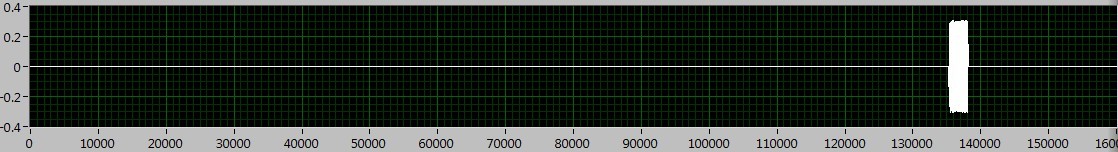
How can I extract the signal of the waveform accroding to the power level? I read the Trigger & Gate .vi, but this vi retrieves the signal duration. I want to extract the signal depending on the power level.
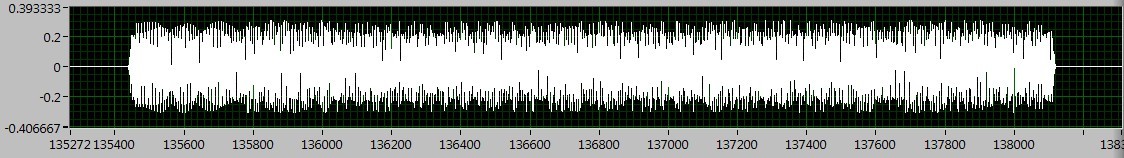
As shown in the following figures, the signal I want to deal with is between 130000 to 140000, if I Zoom, I can see the useful signal is between 135400 to 138200. The question is how to extract the signal in the area?
I tried the sub_NoiseEst_And_Chop_Shell.vi in the example of Packet_based_link also, but this Subvi seems to be a bit slow. Can someone give me the best advice? Thanks in advance!
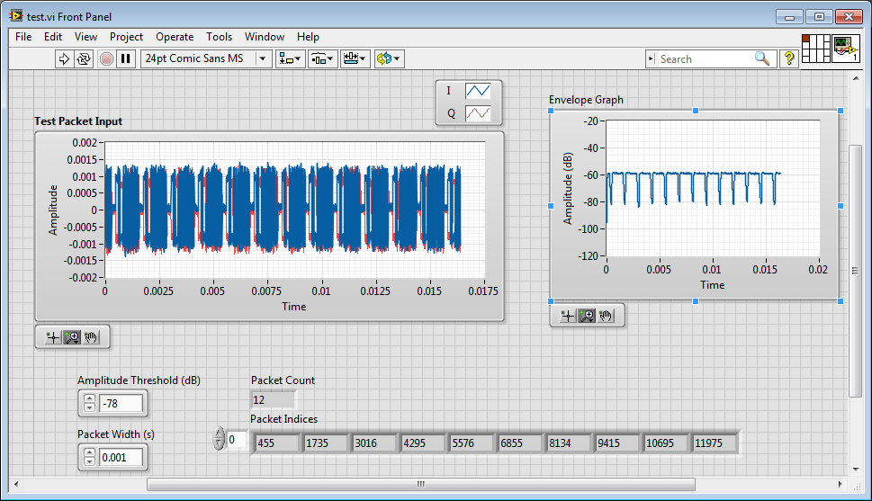
I'm working on something similar, but have not had time to fully develop.
My idea was to use an envelope detector (low pass filter) and then use a detection of energy VI on the envelope.
Here is where I left
-
How to redirect the signal meter
Hi, I use Labview 2010 and 6212 usb Board. I'm generating a signal using counter 0 which, by default, output signal to PFI12. However, I want to signal to PFI2 or PFI3 for example instead of PFI12. The specimen vi that I use to generate signals is attached. Any help would be appreciated. Thank you, vk
Found the answer. Basically, I had to use CO. Pulse.Term property node as shown in the link below.
http://forums.NI.com/T5/counter-timer/counter-output-with-NI-cDAQ-9188/m-p/2218208#M10898
-
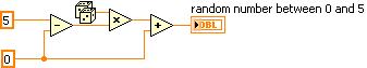
How to generate random numbers from 1 to 5
How to generate random numbers from 1 to 5
-1110340081
Thank you I ended up
-
How to split the signal into small pieces (which have different lengths)
I have a long waveform which is just a combination of a waveform, waveform 0 + one another + 0 +... I would like to have small pieces of the long wave form. The problem is that I can't think at least detect the 0 value to separate them. Any advice would be appreciated.
How are generated segments of zero? They are exactly zero or zero average but with a bit of noise? You know the length of the segments of zero? Is it still the same? One of the waveforms have segments where real values are zero, and, if so, how long these segments is possible?
My first thought is to use in range & force with limits just a little above and below zero. Verification of the length of a set of samples not in Range.
Lynn
-
How to generate arbitrary waveforms FRO meter
Hello
I have a problem in the generation of the wave as shown in JPG below. Need to generate digital waveforms 2
1. with the help of counter0 - digital waveform will be with pulse 60 (58 - good pulsations and 2 empty pulse)
2. with the help of Freqout - digital waveforms should be to synchronize with a 40 pulse signal 2 signal should be high for then 5 impulses.
I tried model digital generation with Boolean 2D table convert to digital waveforms. But somehow, I couldn't have expected waveform.
If someone could help me in this problem.
Thanks in advance
Vijay
FREQ Out is not able to generate either of two waveforms - it can only generate continuous pulse trains. In fact, even one of the complete M-series meters would be unable to generate your "Signal 1" - you must use the 2nd meter to the signal from the door.
Supported boards of series X buffered output of the counter and could therefore be used to generate a waveform. You can use Freq Out yet, but the X series boards have also 4 full meters if this should be enough resources such as Freq Out is not necessary.
Best regards
Maybe you are looking for
-
How can I activate the memory of passwords, not highlighted.
I use windows XP. The latest greatest version of Mozilla Firefox is installed. How can I manage the password section in the tools options security section. He is not highlighted and using a master password has no effect. Help!Thank you
-
MBP stops when no charging current and 99% battery
About a day ago, my laptop (13 '' mid-2012 MacBook Pro) stop when I unplugged my charger. I have tried rebooting, but nothing happened when I pressed the power button. I plugged it in, and it began to restart immediately. Since then, the condition of
-
Restore Win 7 with media non-Lenovo - possible to restore the features of Lenovo?
Rcently a T400 company retired, he converted for home use. Update the operating system on a new SSD became quite the chore, because Lenovo stingy installation communications policy. After playing for several hours, I decided to tighten the teeth, no
-
Photosmart 5510e black blue Scans
I have a photosmart 5510e on a wireless network with windows 7 OS. Recently he changed the scan quality of the printer with all the colors that come out in a lighter version, IE: black sweeping like blue, blue as light blue etc etc. I used the print
-
I built a logo but when I convert it to a JPEG shows the "T" I put on the top blue disappears square shaded and all what is a blue square, but when converting to PDF just fine!