How to import codes Verilog in LabVIEW FPGA?
I tried to import the Verilog code by instantiating followed education in http://digital.ni.com/public.nsf/allkb/7269557B205B1E1A86257640000910D3.
but I can still see some errors when compiling the file VI.
Test file simple Verilog is as follows:
==============================
module andtwobits (xx, yy and zz);
input xx, yy;
output reg zz;
always start @(xx,yy)
ZZ<= xx="" &="">
end
endmodule
==============================
and after you follow the above link, we have created the instantiation as file
==============================================
Library ieee;
use ieee.std_logic_1164.all;
mainVHDL of the entity is
port)
xxin: in std_logic_vector;
yyin: in std_logic_vector;
zzout: out std_logic_vector
);
end mainVHDL;
architecture mainVHDL1 of mainVHDL is
COMPONENT andtwobits PORT)
ZZ: out std_logic_vector;
XX: in std_logic_vector;
YY: in std_logic_vector);
END COMPONENT;
Start
ALU: andtwobits port map)
ZZ-online zzout,
XX-online xxin,
YY-online yyin);
end mainVHDL1;
==============================================
Sometimes, we observe the following error when we put the flag on the output port.
ERROR: ConstraintSystem:58 - constraint
TNM_ChinchIrq_IpIrq_ms; > [Puma20Top.ucf (890)]: INST
"* ChinchLvFpgaIrq * bIpIrq_ms *" does not correspond to design objects.
ERROR: ConstraintSystem:58 - constraint
TNM_ChinchIrq_IpIrq; > [Puma20Top.ucf (891)]: INST ' * ChinchLvFpgaIrq * bIpIrq. "
does not match design objects.
and Interestingly, if we remove the indicator from the port of exit, he sucessfully compile on the LabVIEW FPGA.
Could you take a look at and please help me import Verilog to LabVIEW FPGA?
I followed the basic steps of the instantiation on the link above, but still it will not work.
Please find the attachment for all files.
-andtwobits.v: original file from Verilog
-andtwobits.ngc: file UCS
-andtwobits.vhd: VHD file after translating a simulation model
-mainVHDL.vhd: master of the instantiation
Since there is no sample file for Verilog (VHDL file, there but not for Verilog), it's a little difficult to do simple execution on LabVIEW FPGA, even for examples.
Thank you very much for your support, and I'm looking forward to seeing all your help/answer as soon as possible.
Records,
The best instructions we have for integration Verilog IP in LabVIEW FPGA can be found here: using the Verilog Modules in a component-level design. My suspicion is that you did not uncheck the option 'add the IO buffers' in the Xilinx ISE-specific Options parameter when running XST (see page 8 of the .pdf)
Tags: NI Software
Similar Questions
-
How to import an image in labview
Dear Sir.
How can I import an image two bmp in labview and compare it... taking as reference and others as a sample...
Under the graphic palette and suond, you'll find two pallets more than imagews of the handle and the other image files.
Of those, you can do a pixel-by-pixel comapre.
Ben
-
How to measure the frequency of sampling (s/s) in LabView FPGA?
Hello
I am trying to find a way to measure the sampling frequency (s/s) during which I read from analog input in LabVIEW FPGA. I know that the sampling frequency is specified in the data sheet of the module HAVE, but I want to measure in LabVIEW.
Any suggestions?
A screenshot of the example code would be greatly appreciated
Hey phg,.
If you have some time loopand in this loop, you export a sample by iteration of loop via an I/O node. You can't out two samples on the same I/O node within an iteration, it's always one!
So if your loop takes 1 second to run you have a sampling rate of 1 Hz output. The same goes for sampling of entry. How long your loop takes to run can be calculated as explained above.
Samplerate [s / s] = 1 / [s] while loop
-
How to use bidirectional I/O in the CLIP of LabVIEW FPGA?
How to use or define two-way i/o for CLIP with LabVIEW FPGA? I want to use 1-wire communication inside the kernel CLIP, the function will be implemented to read and write as I/O inside the CLAMP.
The XML Generator (CXG) 1.1.0 ELEMENT does not support.
Thank you
Supawat
Work after separate IB pin (bidirectional) at the entrance and exit. Thank you.
-
Exactly how memory works in Labview Fpga
I use a PXI 7853 and me for the last few days I've been playing with the help of blocks of memory in the FPGA.
Now, I'm relatively new to Labview FPGA programming and this is why I would be grateful if someone could provide me with some clarification on the following points:
(a) given that I work on the development host computer when I initialize memory with the ability to use a memory initialization VI then how does exactly in the backend. What I want to ask is, when I change the values of the memory in the computer development and then compile the FPGA VI in the Board of Directors, what is data memory are brought in the FPGA. If this is the case then in what form are the details initially registered in the development computer.
(b) is it possible for me to use the initialization method VI to change memory n valuesi while the FPGA VI is running. If this isn't the case, then it would make a difference if I stop the VI and then change the values using the Initialize method. Who would actually reflect on the FPGA or should I have to re compile the FPGA VI whenever I change memory values in the development machine, using the "VI initialization method (which is available as an option for us do a right-click on the block of memory in the Project Explorer window).
I tried test with simulation of FPGA VI and found that when I try to change the values of memory by running VI initialization. a pop up that says that it is not possible that the FPGA VI is still in service is delivered.
Any light on this or advice with links would be much appreciated
See you soon
sbkr
sbkr wrote:
(a) given that I work on the development host computer when I initialize memory with the ability to use a memory initialization VI then how does exactly in the backend. What I want to ask is, when I change the values of the memory in the computer development and then compile the FPGA VI in the Board of Directors, what is data memory are brought in the FPGA. If this is the case then in what form are the details initially registered in the development computer.
When you compile the FPGA VI, he will understand the values used to initialize the memory.
Are asking you what happens if you run the VI FPGA on your development computer, and your FPGA VI, written in the memory block, the new values are included when you compile the FPGA VI? No, these values will be lost. The values contained in the bitfile are the values you used to initialize the block of memory, as defined in the memory properties dialog box. The initial values are saved in the LabVIEW project file and the definition of memory block.
sbkr wrote:
(b) is it possible for me to use the initialization method VI to change memory n valuesi while the FPGA VI is running. If this isn't the case, then it would make a difference if I stop the VI and then change the values using the Initialize method. Who would actually reflect on the FPGA or should I have to re compile the FPGA VI whenever I change memory values in the development machine, using the "VI initialization method (which is available as an option for us do a right-click on the block of memory in the Project Explorer window).
You will have to recompile the FPGA in order to use the new initialization values, because these values are part of the bitfile FPGA.
-
[CS5.5] how to import a code snippet in the current page
Hi all
I got IDOMElement of the document UIDRef and imported to the code snippet. Here's the code-
 InterfacePtr<IDOMElement> documentElement(docRef, UseDefaultIID());

 if (documentElement == NULL)
    break;

 if ((status = Utils<ISnippetImport>()->ImportFromStream(tStream, documentElement)) == kSuccess)
    //success
( tStream is the IPMStream of the code snippet that I'm importing)
This code above is able to import the extract with success on the first page of the active document, but I can't be imported into current page instead. So to do this, I tried to get IDOMElement of UIDRef of the current page instead (logically, I thought this will import the excerpt of the current page).
InterfacePtr<IDOMElement> documentElement(currentPageUIDRef, UseDefaultIID());
But the result is still - the documentElement is not null, but the code snippet is imported to the first page only.
Maybe the concept of IDOMElement is not clear to me, but I find that no documentation in the SDK Guide too. Can someone explain to me what is an IDOMElement and how to import a snippet of the current page?
Any help will be much appreciated. Thank you.
Hello Shawn,
have you tried the IDOMElement of the propagation or layer? You can't place items on a page.
Markus
-
LabVIEW FPGA: Integration node clock wrong
Hello
I'm having some difficulties to understand how the clock is part of the node IP for LabVIEW FPGA and was hoping to get some advice.
What I try to do is to set up a digital logic circuit with a MUX feeding a parallel 8-bit shift register. I created the schema for this Xilinx ISE 12.4, put in place and can't seem to import the HDL code into an intellectual property node. When I run the VI, I am able to choose between the two entries for the MUX, load the output in the shift register, clearly the shift register and activate the CE.
My problem is that when I switch to the entrance of THIS, he should start 1 sec shift (Boolean true, SCR, High, what-have-you) in the registry once each clock period. Unfortunately, it instantly makes all 8 bits 1 s. I suspect it's a question of clock and here are some of the things I've tried:
-Specify the input clock while going through the process of configuring IP nodes.
-Adding an FPGA clock Constant as the timed loop.
-Remove the timed loop and just specifying the clock input (I'm not able to run the VI that I get an error that calls for a timed loop)
-Do not specify the clock to enter the Configuration of the IP node and wiring of the FPGA clock Constant to the clock input (I can't because the entry is generated as a Boolean).
-Remove an earlier version of the EC who had two entries up to a door and at ISE.
-Specify the CE in the process Configuration of the IP nodes.
-Not specify this in the process of setting up nodes IP and wiring it sperately.
-Various reconfigurations of the same thing that I don't remember.
I think I'm doing something wrong with the clock, and that's the problem I have. Previously, when I asked questions to the Board of Directors on the importation of ISE code in LabVIEW FPGA, a clock signal is not necessary and they advised me to just use a timed loop. Now, I need to use it but am unable to find an explanation online, as it is a node of intellectual property.
Any advice would be greatly appreciated, I'm working on a project that will require an understanding how to operate clocks the crux of intellectual property.
Thanks in advance,
Yusif Nurizade
P.S. I have attached my schematic ISE and the LabVIEW project with one of the incarnations of the VI. The site allow me to add as an attachment .vhd file, but if it would help I could just paste the body of the code VDHL so just let me know.
Hello Françoise,.
I spoke to the engineer OR this topic and it seems that it was sufficient to verify that your code works, by putting a wait function of 500 ms on the while loop to check that the registers responsible and clear. I'm glad that it worked very well!
-
LabVIEW FPGA: Deploy fpga with host program
Hello people,
I develop using a pxi-7831R (FPGA), 7.1 LabVIEW and Labview FPGA 1.1.0. I wrote the fpga code and a host vi and they work well on my development computer. However, I need to create an executable file and take it to my development computer to another computer (which also contains a pxi-7831R), and I don't know how to do it.
Then I just build an executable from my host program and place the 'bit' fpga file in the same folder as the exe and copy it to the target computer, or what I need to somehow add the bit file to my build configuration?
Thanks for any help!
Chris
Hi chassan,.
In LabVIEW 8.x, the exe will offer the bitfile automatically. I imagine it works similarly in LabVIEW 7, but it's probably best that manually regroup you the bitfile in your build options.
-
How the resets are generated in LabVIEW for FlexRIO
All,
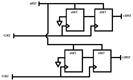
My background is VHDL and Verilog for FPGA and ASIC implementations. I guess LabVIEW has a point, an only synchronous reset to all of its logic. I create a design that is going to be sections of VHDL IP, through IP integration node is instantiated. When writing to the top of my spec, I need to describe how a reset is spread to all the flops in the design that will be peer-reviewed of accuracy of the results. I need to understand exactly how LabVIEW handles resets to other areas of the clock.
A simple case is the following: I have a 50 MHz external source synchronous data interface and will be a limited treatment of data in this area of 50 MHz using an IP integration node. This IP is designed to have the flops to reset synchronous on the 50 MHz clock.
Separately, I have my most of my treatment and storage to the host (via DMA FIFO) in a field of 100 MHz clock, derived from the clock of 40 MHz I base I must transfer data from 50 MHz to 100 MHz using a FIFO. This treatment at 100 MHz contains a floating-point operations that are reset to zero synchronously to the field of 100 MHz.
In this scenario, you see I have two areas of clock with synchronous resets. I need to understand how LabVIEW FPGA create reset signals which are entries to my integration IP nodes, in order to understand if I need to incorporate any reset synchronization within my VHDL circuits.
Thanks for any help and if you need further details or context, please let me know and I find out additional details.
-Jim
Hey Jim,.
So, option 2 then... in this case, you are looking at a signal of asynchronous reset and must realize in your VHDL similar to the following to ensure that your resets are say synchronously.
-
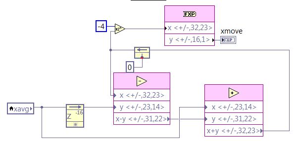
I created a Labview FPGA .vi using a structure flat sequence that shows the output of a sensor at a sampling frequency of 1 kHz on a digital SPI. After reading, I write the point data fixed in a FIFO, which is read by a host vi and finally written on the hard disk for post-processing. I need to add logic for the calculation of the average for the further process the signal FPGA vi. I want to continue at the exit of the original 1 kHz sampled datat to the FIFO, but also perform a sprawl on the steps and write these results at the same frequency of 1 kHz to the FIFO. The average feature, I would like to implement is a two-step process. Step 1 is to take samples of 1 kHz and perform an average of 16 samples based frame. In other words, I want samples of sum 16 1 kHz and dividing by 16 and decimate 16:1, which produces data of 62.5 Hz. Step 2 is to take 62.5 Hz sampled data and perform a moving average of 16 samples on these data and output resulting at the same sample rate of 62.5 Hz. I want these 62.5 Hz sampled data to be injected into the FIFA as well as the original data of 1 kHz sampled (unmodified) at the frequency of 1 kHz.
I've got step 1 work correctly using the block "mean, Variance, StdDev FPGA vi" with number of samples on 16. This block runs within a sequence of flat sequence structure after I received each sample 1 kHz on the SPI. My fight is the average feature mobile step 2. I try to use the code in the screenshot below, but am unclear regarding how/where to implement this logic inside is my structure flat separate sequence while loop, structure of the case, etc, in order to ensure that it only works on one of 62.5 Hz samples to this flow of data at once. I tried to put it inside the sequence that executes the block average and further in a case that is driven by the Boolean "valid" the average block output. I obviously don't understand how these different loops run, because it does not work properly. Can someone tell me how to implement the logic of moving average in my vi FPGA existing to produce the desired results as described above? Screenshot below of the logic (step 2) average mobile I am trying to use. In addition, find attached my screws vi FPGA that I need help with is 'CA215_SPI.vi' and the level vi host is 'Host.vi '. Thanks in advance.
Joel
This question is closed. I realized that my approach to implementation was actually working. I just had a stupid mistake on my fixed point output bit size, giving me results errenous.
-
How to import several pictures folders, including automatically created albums?
Hey there,
First of all, thank you for helping me with this one.
I use Picasa and organize semi-automatiquement all my photos on my hard drive. Given that Picasa will be abandoned, I want to spend all my photos/videos photos. What I get is, how to import a single folder in Photos and automatically creating a photo album. But I can't do with several files because I fight with Automator. I found some tutorials intestine on the web, but not for my particular situation.
What I did (see screenshot):
(1) departure of workflow must be the parent folder, and Automator should go in its subfolders and take one after the other.
(2) now I need a variable to record the name of the folder. The name of the folder must be the new name of the photo album.
(3) the final step is to Automator to import a record after another and create a photo album with the same name as the current folder.
If I do, I have the problem that all imported as one (without subfolders) and the name of the album is always like "... / Desktop. I couldn't find solutions to this problem. Does anyone know what I need to add to Automator to do what I want?
Any help is greatly appreciated.
Thank you very much!
Andreas

This Applescript looks like it will do what you want
(I found this with google, I don't have test it)
Try on a few test first file and backup before using
Leading to: https://github.com/codez/ImportPhotoFolders
What links to: https://github.com/codez/ImportPhotoFolders/blob/master/ImportPhotoFolders.apple script
Example of
Given the following directory structure:
- Photos.
- Mountains.
- Asia /.
- Everest.jpg
- K2.jpg
- Europe /.
- Matterhorn.jpg
- Asia /.
- People /.
- i.jpg
- mejenny.jpg
- whatever.jpg
- Mountains.
When you select the
PicturesDirectory to be imported, the following structure is generated in Photos:- Images / (folder)
- Mountains / (folder)
- Asia (album)
- Everest.jpg
- K2.jpg
- Europe (album)
- Matterhorn.jpg
- Asia (album)
- People (album)
- i.jpg
- mejenny.jpg
- Photos (album)
- whatever.jpg
- Mountains / (folder)
Applescript can be found at: https://github.com/codez/ImportPhotoFolders/blob/master/ImportPhotoFolders.apple script
- Photos.
-
Simulate the sine wave using LabVIEW FPGA with NOR-myRIO and display in real time
Hello
I'm relatively new to LabVIEW FPGA. I am trying to test (and later apply) controllers high speed on myRIO.
At this point, I'm trying to simulate the sine wave from 1 to 10 kHz using Sinewave generator VI express. I also intend to display the sine wave on the time real (RT) using FIFO. However, I had a bit of trouble to understaing various synchronization parameters.
1. how to encode information about the sampling frequency generating sine wave? (The side FPGA vi requires only the frequency of the signal and possibly phase and does not rate update lines)
2. how to estimate the number of items in a FIFO? (that is, the relationship between the rate of updates to loop (RT), the signal frequency, sampling frequency and the number of items in the FIFO)
It would be great if we could share a very simple program (side host and target) that did something similar.
Thank you
MILIN
Milot,
I think the problem is the type of data in your FIFO. Your FIFO is configured to use a data type of I16. The problem is the number, it displays only ever will be-1, 0 or 1. To resolve this problem, you must send the sine wave as a fixed point data and convert it to a double on the side of the RT. This should significantly improve your resolution.
-
How does the library function call Labview? Can I emulate using C++?
Hi all. I recently finished writing a dll CUDA for LabView, and now I'm in the steps of optimization of code, memory management, etc. BUT since my code depends on the entries of Labview (lots of data under types of specific data as table manages and Clusters labview) I can't use the CUDA Profiler or the Profiler VC ++ on the DLL. What I intend to do runs labview and then out of all data entry for the DLL in a binary file and then add an additional function in my code that will read in the binary file, allocate and assign variables to their respective positions, and then call the specific DLL function in Labview. In the end, this miniature function will act as the library function call to my specific group of data entries.
In any case, I started to make this purchase all my data entry of cluster and it comes out in a binary file. And then I started the initialization of the handles of labview, allocating memory and begins to write the binary data in the memory and it works for integers (ints), floats, etc., but I'm confused on how it works with table handles!
Some examples of code:
Sets the Handle for table 1 d for INT
typedef struct {}
int length;
int val [1];
to access the value in a row-online val [Online]
} Array1dInt, * Array1dIntHandle;int main()
{
Array1dIntHandle x = new Array1dInt *;
(* x) = new Array1dInt;ifstream file ('TESTDATAIN.dat', ios: in | ios::binary);
If (file.is_open ())
{
file ((char *) &(*x)-> length, sizeof;)
file ((char *) &(*x)-> val [0], sizeof (int) *(*x)-> length);LabviewSpecificFunction (x);
leader. Close();
} else
{
< "file="" did="" not="" open!"=""><>
}
return 0;
}__declspec(dllexport) LabviewSpecificFunction (Array1dIntHandle x)
{
...
}However, my program crashes when the table is nominally big, and it is expected, because if we look at the Array1dHandle, it has allocated only enough memory to 1 item of value! YET, somehow, in its magical and mysterious labview is capable of making val [1] be val [HOWEVERMANYYOUWANT], even if C++ 101 says that val [1] is a constant pointer, and even if I dynamically allocated memory another somwhere, I would never be able to put these data in this round!
Can you explain, or maybe even write example on how I can fool my program into thinking that the binary code comes from labview, so I can then run my program independent of allowing me to profile the functions inside labview?
I hope that this question is clear and my sample code is also clear, but I'm happy to answer any questions that relate to this.
Thank you all!
I think that I thought about it.
Array1dIntHandle x = new Array1dInt *;
int tempsize;

file ((char *) & tempsize, sizeof;)

(* x) = (Array1dInt *) malloc (sizeof (int) + sizeof (int) * tempsize);

(* x)-> length = tempsize;

file ((char *) &(*x)-> val [0], sizeof (int) *(*x)-> length);
Well enough, you will need to make the handle, and then make a new Array1dInt * for him, then read in the length of the array in a temporary variable. Then use this information to then malloc memoery quantity you need for the table and pass this place on the handle. Now the handle will point to the size of the memory and you will be able to access the memory in the format, you've done the handle. Badabing badaboom
-
Move from LabVIEW FPGA block of ram address to node CLIP?
Hello
I need to pass an index memory RAM of LabVIEW FPGA block to a CLIP node to the node CLIP to have access to the data in the BRAM. The node of the ELEMENT contains an IP address that we developed and the IP address is the use of Xilinx BRAM driver to access data. I guess that we need to move the physical address of the BRAM to the ELEMENT node.
Is this possible? If so, how? If this is not the case, what would be an alternative?
Thank you
Michel
If I understand you correctly, Yes, you should be able to use the memory block of the Xilinx pallet Builder in LabVIEW FPGA and in the loop of the single Cycle, connect the ports of this block signals CLIP exposed by the IP of your colleague. You may need to tweak/adapt some of the signals slightly to the LabVIEW data flow.
-
LabVIEW FPGA CLIP node compilation error
Hello NO,.
I work on an application for my Single-Board RIO (sbRIO-9601) and faced with a compile error when I try to compile my FPGA personality via the ELEMENT node. I have two .vhd files that I declare in my .xml file and all at this point works great. I add the IP-level component to my project and then drag it to the VI I created under my FPGA.
Within the FPGA personality, I essentially have to add some constants on the indicators and entries CLIP to my CLIP out and attempt to save/compile. With this simple configuration, I met a compilation error (ERROR: MapLib:820 - symbol LUT4... see report filling for details on which signals were cut). If I go back to my VI and delete indicators on the output (making the output pin of the CLIP connected to nothing), compiles fine.
I've included screenshots, VHDL and LV project files. What could be causing an indicator of the output of my VI to force compilation errors?
Otherwise that it is attached to the output ELEMENT, a successful compilation...
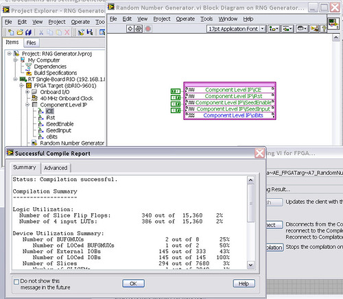
After that the output indicator comes with CLIP, compilation to fail...

NEITHER sbRIO-9601
LabVIEW 8.6.0
LabVIEW FPGA
Windows XP (32-bit, English)
No conflicting background process (not Google desktop, etc.).Usually a "trimming" error gives to think that there are a few missing IP. Often, a CLIP source file is missing or the path specified in the XML file is incorrect.
In your case I believe that there is an error in the XML declaration:
1.0
RandomNumberGenerator
urng_n11213_w36dp_t4_p89.vhd
fifo2.vhd
This indicates LV FPGA to expect a higher level entity called "RandomNumberGenerator" defined in one of two VHDL files. However, I couldn't see this entity in one of two files. If urng_n11213_w36dp_t4_p89 is the top-level entity, edit the XML to instead set the HDLName tag as follows:
urng_n11213_w36dp_t4_p89 Also - in your XML, you set the 'oBits' music VIDEO for output as a U32, however the VHDL port is defined as a vector of bits 89:
oBits: out std_logic_vector (89-1 downto 0)
These definitions must match and the maximum size of the vector CLIP IO is 32, so you have to break your oBits in three exits U32 output. I have added the ports and changed your logic of assignment as follows:
oBits1(31 downto 0)<= srcs(31="" downto="">
oBits2(31 downto 0)<= srcs(63="" downto="">
oBits3(31 downto 0)<= "0000000"="" &="" srcs(88="" downto="">Both of these changes resulted in a successful compilation.
Note: The only compiler errors when you add the flag because otherwise your CUTTING code is optimized design. If the IP is instantiated in a design, but nothing is connected to its output, it consumes all logic? Most of the time the FPGA compiler is smart enough to get it out.

Maybe you are looking for
-
HP 15: I'm just staring at a black screen
OK, so I've had this computer for a good year, and I have to admit, I'm a little clumsy and I drop my computer, not from a high place or anything but perhaps falling about 5 feet but still after a few falls, he worked still, in my view, that I had dr
-
I just bought a second HP Mini I think the form/Windows 7 netbook my needs to a T. I use it much more than my laptop Compaq Presario or one of my pills. My question is what do I do with the new Mini to the death of my current Mini? -Just put it on
-
When my computer is turned on, the power button is lite on the monitor of green color. When I turn off my computer, the power button is lite on my monitor goes to orange. to activate the orange lite off the monitor, I have to manually, press the powe
-
How can I see all the restore points?
I have Vista and my system has become unstable - black screen and no reply until I turn off computer with switch. I decided to do a restore. Come to the window to restore the system, but only two show Restore Points - yesterday and day before. But th
-
Reduzierung LR 6 (standalone) auf LR CC 2015
Liebes Forum,ICH habe von LR6 auf CC2015 LR media, im Züge eines von LR und PS Abos. French kann ich however LR nicht mehr über den "Öffnen-button" uber die CreativeCloud application starten:ES passiert schlichtweg gar nichts. PS startet uber den pro