HP 70950 osa and 8163a multimeter
Hi, I'm new to this forum, I'm looking for help to create a Labview basic program to communicate with an old HP70950A optical spectrum analyzer, connected via GPIB to a Win98 computer where Labview 6 is installed. There is no pilot available, but just the BASIC HP Manuel. I would get through the usual PLAYBACK controls / WRITING, the amplitude of crest of slider and, ultimately, the wavelength. Any additional command to control the instrument is welcome.
I'll get these data according to the power measured Agilent 8163 a multimeter, for which it has the drivers already.
Thank you
Antony
antony_sc wrote:
which function to use to succeed in the Labview program? RECEPTION following the SENDING does not work. I tried to play with time, to see if it is a problem of communication, but it is not.
My view is bad enough already, so if you could be kind to us old people, could you use a normal font in the future?
Well, the receive function would be the equivalent of the function in LabVIEW. What do you mean by "it doesn't work"? You get an error? If so, what is this error? Still, I would agree with Dennis, you must use the VISA.
Tags: NI Hardware
Similar Questions
-
How to build a drag and drop multimeter lead using Flash animation?
I'm building a virtual multimeter to test simulated circuits. I would like to be able to drag a lead animation test multimeter to a circuit point and drop it on a target. The static drag and drop is not my problem. I would like some suggestions on how I can animate the movement of the head itself. Any suggestion would be appreciated.
you want something to "follow the mouse", but do not be dragged?
If so, use a loop (enterframe) and facilitate the position of the object with the mouse:
Object.x += speed * object.x +(1-speed) * mouseX;
-
My HP dv4-1145go is dead - no lights, no video, nothing.
A few months ago my dv4 has stopped working. It is a device I want to make it work, in order to prevail on the TRIPS Agreement and use it for email and web browsing.
My diagnostic skills are limited and a multimeter is the extent of my test. I don't want to spend money on the wrong parts, but I'm willing and able to replace the motherboard if it is the right solution. Given to nine are available on the Internet within my price range, which is around $100, as the machine is 5 or 6 years.
Your experts can help me greatly in commenting and suggesting steps that I take to diagnose the problem. Here's what I've done to date.
During the inspection, I first noticed that the power jack led was, so I traded the power adapter external with another one of HP brand and nothing has changed. I tried the power dv4 adapter, also with a label of HP, on my HP dv6700 and it worked correctly. So for now, I think my adapter is good.
Then, I removed the motherboard from the folder and it inspected for burnt components or other signs of deterioration. Nothing is obviously broken or burned, but I found a "fist" full of dog hair that I removed the fan. Don't know if it was enough hair to stop the fan and the overheating of the device. I worry about the processor is damaged, but do not know how to check. Any comments on this issue will be greatly appreciated.
To be on the safe side, I ordered a power supply and cable for a modest sum of money. He is yet to come, but seems to be a wise investment.
That is the measure of my efforts, and I hope that an expert will take my fate to heart and make comments and suggestions to help me find the cause of failure of the laptop. Then, I can better decide on the right solution.
Thank you.
Thank you very much for the compliment and the suggestion to move forward. I'll do what you suggest. Look at this post for updates, but I can take the time in all this is done. Thanks again.
-
Ammeter reports an incorrect value
I resolve this circuit with the method by mesh currents. I just installed NI MultiSim, and I expect to use to check my answers in school this semester. The first problem was the solution to the back of the book, so I decided to try Multisim for this purpose. After solving the circuit by hand (twice, I messed up my linear algebra) I plugged in the MultiSim circuit. The ammeter and the multimeter declare a value of 4.815 kA. The text book and my calculations return a value of 6.25 amps. I tried everything I could think of, nothing helps. I'm doing something wrong? Is the method by currents of mesh trumped by another tool of the analysis that I do not know? Please help me, I would like to be able to get instant feedback on my homework. Thank you
Rewire your connections to R3, R4 and ground. They did not "connections." There is no point of connection about to mass. If you drag R4 to the right, you will see that it is not connected to R3 even if there is a connection point. Perhaps it's second nature to me, but I've always done my junction connections tick at least one of the grids of the component. It seems that there may be a problem any trying to make a second connection to the right of the element.
-
Hello
I have a source Keithley 2400 meters and a multimeter Keithley 2010. I measure the temperature of a loop of water with an RTD, and I measure its resisitivity 4W with the K2010.
I can cool and also heat this water via a Peltier heat pump loop. The applicable range is - 1Amp< current="">< +1="" amp.="" so="" i="" use="" the="" keithley="" source-meter="" to="" drive="" the="" peltier="" in="" this="" range.="" negative="" current="" cools="" the="" water,="" positive="" current="">
I have the kit with LabView 2011 PID.
My only question is that if I give + -1 as the entry level of the PID.vi, it's a good way to implement this task?
Thank you!
Hi man,
Perhaps you need to set the range of output on [-1, + 1]?
-
GPIB hangs - no way to disable it programmatically?
I have a test configuration with power, scope of tek, generator functions of agilent agilent and agilent multimeter, everything on gpib. I have the usb interface. My pc is xp, my program is c, very simple. It emits just ibwrt and ibread.
It extends over a long period (sometimes days), but ends by crashes. When it does not crash, I can run the utility of OR and see the gpib controller. But analysis of the instruments will expire and return with any found.
I can free the gpib if I push the 'local' button on the power supply. Then everything works. Feeding is an agilent 3631.
I don't think that there is nothing wrong in my program. I think that the power supply block the gpib. Not sure what makes this happen.
Is there a way I can erase the gpib programmatically? I mean other that push the 'local' button manually?
No idea how to prevent power to do this?
brand
View the source code, there may be something that someone else will see a problem.
Curt
-
LabVIEW a too slow DMM readings
Right now I'm working on a program that takes readings of a multimeter and puts them in a graph. The multimeter done readings at 100 per second, while LabVIEW takes only a number between the meter every five or six seconds. I am very new to LabVIEW, so I don't know if there is something in my program that slows down or something I can add to increase the frequency of performed readings. I joined the program file that I use and the multimeter is a Tektronix DMM4020, although I don't think that the problem is with the multimeter. Any advice would be great, thanks in advance. Rach
-
status = viOpenDefaultRM (& updateSession);
status = viFindRsrc (updateSession, "GPIB0? * INSTR "(, & FListe, & numInstrs, desc);"
If (status<>
{
viClose (updateSession);
}
{while (numInstrs)-}
viOpen (updateSession, desc, 0, VI_NULL, & updateName);
viClose (updateName);
viFindNext (FListe, desc);
}
viClose (fList);
viClose (updateSession);
updateSession = VI_NULL;The above program is the 'OK' button callback function in .uir. First of all, I turn on a single instrument, click on 'OK', it gets an address ("desc"); Secondly, I turn it back on another instrument, click on 'OK', he gets two addresses. Finally, I turn off the first instrument, click 'OK', but it gets even two addresses. There is no error in this process. Anyone can answer this question?
I tried MAX, this is the same problem.
I have two instruments GPIB, Agilent DC Power Supply and digital multimeter Agilent.
I start to MAX--> view--> Refresh, it shows there are two GPIB instruments, even if I already have an order.
When I click on "Open the VISA Test Panel" for the disconnected instrument, it returns "failed to open session...". »
So I thought if it is the problem of compatibility between NC and Agilent. Is there any other command which behaves like viFindRsrc without problem?
Thank you.
-
I have an iphone 6 it is damaged by water but I set myself and the person put it on charge and tested it with a multimeter and it worked perfectly but when I went to get a screen tested on it because she does not have the person had not on is it did not work, even if the person has used only flow to correct and get a few corosions out with the replacement of some components of the person responsible for 10 minutes after having plugged in and the battery it wamer so it as I said her test with a multi meter test and he registered 12v and I wondered if something was wrong with it and if I could fix it easily?
Check the liquid Indcator of Contact.
Instructions here > liquid for iPhone or iPod is not covered by the warranty - Apple support
Just so you know, the service of the liquid damage to an iPhone or iPod is not covered by the limited warranty of one Apple or an AppleCare Protection Plan (APP).
-
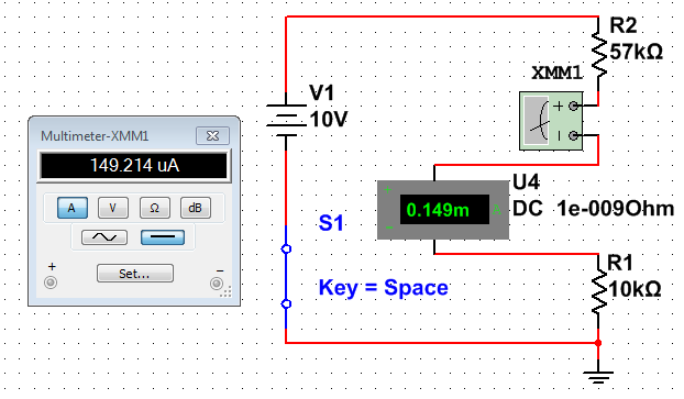
Ammeter and not agree multimeter.
I created a circuit simple transister four-resistant-biased, using an ammeter to display the current. I expected au and became my. So I pulled the circuit part tried to diagnose the problem and finally thought to add a multimeter. In the attached picture, they measure the same current, but display different results. Can someone help me understand why?
149µA = 0.149mA
-
MagSafe adapter does not work after all the stuff that followed and merge card Ok?
My Megasafe duck-head adapter used with a Macbook pro has stopped working while my back was turned!
After trying all the controls and the actions described in the Apple support pages, it always dows not turn on or show any current to the small pins when checked with a multimeter.
It is the death of the adapter or can it receive some kind of CPR?
Chris.
Hello!
Could specify you which checks and actions you have done already?
Your MacBook came with both a cable to connect to the power supply and plug adapter. Could you try both to see if it works? You might just have a broken charger.
Please find instructions for that here: reset the management system (SCM) controller on your Mac - Apple Support
If the battery is good behaviour
- Stop the Mac.
- Plug the MagSafe or USB - C adapter to a power source and to your Mac.
- Use the built-in keyboard, press shift-control-Option on the left side of the keyboard, then press the power button at the same time.
- All the keys to unlock, then press the power button to turn on your Mac
If the battery is removable
- Stop the Mac.
- Unplug the MagSafe from Mac power adapter.
- Remove the battery. (Learn about removing the battery in the MacBook and MacBook Pro computers).
- Press and hold the power button for 5 seconds.
- Reconnect the battery and the MagSafe power adapter.
- Press the power button to turn on the Mac.
Thanks for posting the results!
-Nils
-
Multimeter simulation Multisim not showing after reading press simulation
I'm running student multisim version 14. I made a very simple circuit and to place two multimeter and run a scan dc.
But the problem I am experiencing that I'm window calculation but multimeters not show any value of simulation.
can someone help me understand this please.
Hi shabeesatsangi,
The meter components are intended to be used during the interactive simulation. When you run the DC OI analysis, you will see the results in a table in the grapher.
To display the values in your multimeters, change your simulation mode to Interactive and run the simulation.
I hope this helps,
Jeff
National Instruments
-
Read a resistance of the diode by vs NI USB multimeter
Hello
I read a resistance of the diode at some entrances to supply voltage
and I found that
to 0.2 V
the value of resistance by NI USB-6212: 200 ohms
the value of resistance of meter: 2 kohm
0.5 v
the value of resistance by NI USB-6212: 500 ohm
the value of resistance of the multimeter: 5 kohm.
Could you please let me know why the values are different by 10 times?
Thank you.
No - we can't measure the resistance in this way.
To measure resistance, you normally spend a current known and then measure the voltage. A DMM will be repeated by generating a little known current and measuring the internal tension. If you provide an external voltage thus, DMM internal resistance measurement will not work.
For the LabVIEW - The USB-6212 can measure the tension. If you want to measure resistance, while the unit is plugged, you need to know/measure current (for example through a shunt resistance) and the tension and then do R = V / I for the resistance. I don't know what the argument of type 6212 if you try to perform a measure of 'resistance', as it is not a source of internal current.
Oh, I thought that this all seemed familiar - here's a similar thread: https://forums.ni.com/t5/LabVIEW/daqmx-resistance-measurement-6251/td-p/3267084
-
Hello
We use the DMM and SMU-6363 map to test a hardware device. We will also use a PXI-2530 b switching matrix. We will use the digital multimeter to perform the measurements of voltage, DC and AC, measurements of impedance (2-wire and 4-wire), frequency and waveform acquisition. Can the PXI-4071 left be 4 wire connected (black jacks taken connected and red connected) mode and still be used to perform all other measures (including 2 impedance of the cable). This would simplify the switch connections.
Current measures use the son + and LO, but the HI and S-can remain connected. The problem you are having is if you have an active device the digital multimeter and take you a 4-wire resistance and the measurement of voltage with all 4 wires connected and then change to a current... When you do this, short-circuit you the terminals of the DUT, on that you just take the measurement of the resistance. If the terminal HAD, say, a power supply 10V, then you have just shorted out. Of course, this isn't a problem if your Instrument is a passive device, or if you change just the unused two lead whenever there is an active device of low impedance.
If you want to make voltage, current and 4-wire resistance, you need all 4 wires. If you want to do the voltage and current, you will need 3 wires, but you could connect the s + Hi and then just do the two wires. I vote running every 4 son to your DUT for maximum flexibility.
2-wire resistance is a must if you are measuring resistance above 10 MOhm. Alternatively, you can use 4-wire for all measures.
-
purchase of a multimeter digital usb for labview
Hey guys, im a total newb to this program, but im already addicted. I did a multimeter on a voltage regulator interface and the kit from velleman k8055. but I think that id like better accuracy. are there affordable digital multimeters with two entrances, this interface with labview via USB?
I thought it would be good to get some recommendations here.
Take a look at...
http://www.mccdaq.com/products/usb_products.asp
They do not have a stand alone DMM but it may be something you can use way less than $1300 NOR wants to their DMM unit. I'm under a lot of equipment with excellent results! ... MCC is a subsidiary of OR, if this is useful. :-)
Maybe you are looking for
-
I am a big fan of the Elder Scrolls and uses the new 2.2.9 STEP Setup. They went to the organizer of the Mod (MO) and I can't seem to get my FF working with the mod download things part. I click on the icon "Earth", that takes me immediately to the p
-
Compaq Presario CQ57: I need to reload my OS Windows 7
I accidentally deleted my recovery partition and need to reload the Windows 7 Home Premium 64-bit. I have the product key and I am the legal owner of this computer. Can I get a link to reload it? If there is a charge, how much? Thank you!
-
Can I use speech recognition to dictate something pre-recorded device
I tried to use speech recognition to dictate a few minutes of a recording on the computer device...
-
HP Pavilion 15-ak112nl Gaming: Hp 15-ak112nl RAM compatibility
Hello I would like to know if HP 15-ak112nl supports DDR3 and DDR4 RAM. If so, I would like to know if this RAM is compatible: Thank you.
-
Hello! A delicate... I have a label that contains the text: {Label ID: myLabel "text:"Relaxation InvokeTarget THIS_WORD here" } What I want to do is call a target to invoke (set in my app) when the user clicks on "THIS_WORD" on the label... the kind