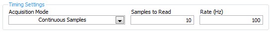
I want to do simultaneous 180 continuous signal phase (square) to 2 analog outputs
Hello
I would like to use a meter to trigger (internally) 2 outputs analog, such as the continuous AC signal to each output is shifted 180 degrees.
I hoped to do with no external connection in addition to the ao0 and ao1 was to use a timer as a trigger counter and have a trigger analogOutput on the front and the other trigger on the falling edge to get the required result.
However, it doesn't matter how I get there. An absolute requirement is that two continuous AC signals are present to ao0 ao1 outputs and they are out of phase by 180 degrees and all trigger occurs on the PXI bus with no other connections external that is frequency of 25 Hz. My card is an SMU-6363.
I was hoping to get the hardware to do all the work of relaxation but if there is a trigger of software approach that would be
Thank you
That's what I ended up doing. microseconds is quite good enough.
Tags: NI Hardware
Similar Questions
-
variable phase shift between two analog output signals
Hey! I would drive two different piezo elements with an sine - / square signals and have a phase shifted output signals. After some trail and error, I was able to get a second analog output on my card PCI-6221 (using LabView 8.2) also allowed me to have different amplitudes for both signals. However, I could not output signal having a frequency different and most importantly to my request to have one of the signals variably shifted phase.
Thanks for the very useful suggestion. I have attached the file .vi installation I've run so far.
Hello!
A way to generate waveforms is using the analog waveform Toolbox. I created an example VI that is attached and that shows you a way to use the base generating function VI. I saved for LabVIEW 8.2.
I hope this helps!
-
6733 continuous signal output generation.
Hello
I want to use an NI PCI-6733 map for generation of continuous signal output.
I downloaded the modules OR measure small DDK OR 671 x & 673 x examples (PCI & PXI) and run the samples.
Our goal is to put a few samples in the FIFO buffer and use the external update (on PFI5) to send the samples to the exit.
Essentially a combination of AOEX4.cpp and AOEX6.cpp example should work.
However, example 6 uses board-> DACDirectData0.writeRegister (.) to set an output value.
To update the output, I use the following code to generate a wave of block.
Sub
NIPCI6733Card: nPoll_Test_T6() / / function called at 5 kHz
{
t67xx * Council const = & GetNI();
Support * const theSTC = & GetSTC();////////////////////////////////////////////////////////////////////////////////////////////////////////////////////////////////
theSTC-> Joint_Reset.writeAO_Configuration_Start (1);
theSTC-> Joint_Reset.setAO_Configuration_Start (0);
theSTC-> Joint_Reset.setAO_Configuration_End (1);
theSTC-> Joint_Reset.flush ();
////////////////////////////////////////////////////////////////////////////////////////////////////////////////////////////////Board-> DACDirectData0.writeRegister ((OutputHigh). 0400:0 x 0 x 0);
Board-> DACDirectData1.writeRegister ((OutputHigh). 0400:0 x 0 x 0);
Board-> DACDirectData3.writeRegister ((OutputHigh)? 0100:0 x 0 x 0);OutputHigh =! OutputHigh;
}
My frequency of update of application (the election) is 5 kHz. The output should run on 15, which means that each update I need to resolve before the 3 samples. I want to use FiFo for this.
(Note: the output is triggered by PFI5 at 15 kHz)
My idea is to 3 samples in the FiFo buffer each update of the application and leave the external trigger update of the output.
Example 4 uses the FiFo. However, this example stops after 5 running running the same fifo data.
How can I set up FiFo continuous data?
370735e.PDF manual describes the following:
With non-regeneration, old data will not be repeated. New data should be
continuously written to the buffer. If the program don't write new data to
the buffer at a speed fast enough to deal with the generation, the buffer
will be negative and cause an error.This is what I want. Is there an example?
Kind regards
Peter
Dennis,
Thanks for your reply.
I have whil post-its on the correct Board.
I implement for IN-Time. It is a time real OS for Windows.
Kind regards
Peter
-
weak continuous signal low-pass filtering
I get continuous signals to the NI USB-6259 of multifunction DAQ device is acquiring its signals to 1000 Hz. The rate of data acquisition can be changed through the GUI, but that
is for later analysis. The main issue here is labwindows offers many options for filtering. I was wondering if someone could recommend the best option for a LP
Filter on a frequency of 50 or 60 Hz. are there - it implemented an easy way to put this. Basically, I want to filter the data acquired and then store it in the file that is currently present.
I was also wondering if material 6259 filtering, if it's a better road then should I use the filter material to clean noise signals?
mdmorar,
The reason why you get this error is the low-pass filter property is is not supported on the USB-6259. You will need to use a filter software for your application, because there is no low-pass filter in the material. If you look under the range of libraries in CVI and select Signal Processing > IIR digital filters > features of filtering in a single step, it will give you options for different low-pass filters. They have some low-pass filters here that should help you.
-
Amplitude measurement of a continuous signal in a given time window
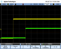
I'm working on an acquisition system that acquires a continuous signal of 250 kHz. My goal is to measure the amplitude peak-peak of the first reaction of signal, the problem with my setup, this is the first part of the signal is always higher than the part of the signal that I'm interested. If I try to use the measure of max from Ridge to ridge of signal VI then responds with the measure of Ridge Crest of the initial part of the signal. See the attachment for a better understanding, I would still like to view the raw signal as is, but I would like to measure the peak voltage at peak of the signal between the yellow sliders.
Thanks in advance...
If transient initial always occurs in the first 12 microseconds, you can use any subset of table or similar wave function to retrieve the last part of the wave. Then use the measurement from Ridge to Ridge on this subset.
Lynn
-
Redeclenchables/continuous to a custom waveform analog output?
Hello
I try regular output an analog signal using the box USB-6211 and Labview2009. I looked at various examples of waveform, including the retriggerableAO.vi example, but I can't seem to understand how to send a 'waveform' custom stamp (terminology is perhaps the question). In all the examples (including waveformbuffer), I ran across the single waveform, the options are sine, square, etc. Previously, I posted on this forum looking for hardware suggestions (link here) and explained what I try to do and got the big help. To sum up, I would like to read a 'waveform' from a text file, send it to the usb-6211 buffer and then continue to an analog channel. At the same time, I'll use the beginning of the analog task to trigger a digital signal once per cycle as well.
I got in what concerns the establishment of the waveform, but am stuck to figure out how to get into the buffer and setting the frequency, etc.
Thank you
Gabe
Hi Gabe,
Dennis is correct that it will take some room to modify the existing screws to fit your need. As he says, the Con Gen tension Wfm - Int Regeneration.vi Clk - no example provided with LabVIEW. In the example, it can be shown that there is a custom VI used to explain the problems that arise when a waveform of a given frequency to a frequency of sampling and outputs analog specified.
With all that said, it seems you want to read from an existing waveform file that you created and this waveform to an AO output channel. There are a few things that will be needed to know before proceeding:
-What is the waveform as you try to output (5000 samples, 10 k, 100 k, etc.)?
-What pieces of the size of the wave you want output (100 samples at a time, etc.)?
-you want to again and again, or simply run through once the waveform looping?
Assuming that you already have the waveform and will only step by step, here's what I would like:
-break the large waveform into smaller pieces of waveform of standard size
-import the waveforms in LabVIEW and create an array of waveforms
-bring the waveform in the example Dennis mentioned previously with automatic indexing enabled on the tunnel
-Remove the generator of wave functions existing the while loop
-wire your indexed table of waveform for the data of the VI DAQmx of analog output terminal
It is possible that you will have to play with the settings of your waveform and timing of your VI, but this should be a good starting point. Please let me know if something is not clear or if I have misunderstood your original message. Have a beautiful reast of the day.
Best,
-
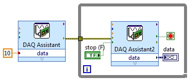
Acquisition of multiple simultaneous analog output data
Hello, I'm doing a program when a user telnet to my computer and labview will recevie provided cn and analyze. then, he deciphers the emssage find what analog output it trying to change and then change it. I all the work, but I get error 50103 who say I can't have 2 screws DAQ assistant express running simultaneously. I want to have 2 different signals on A0 and A1 on my surfboard USB-6281. Is this possible? Thanks in advance. BTW im using labview 8.2
The vi in LV2009 is attached. I did the mods I had described. It should be a beginning. Modify if needed.
-
Several simultaneous analog output channels
I use DAQmx-NOR-USB.
I want to simultaneously generate two analog output signals, i.e. change the two outputs at the same time.
Simple example:
What is happening is that instead of two outputs simultaneous modification, there is 1mS delay:
I want to generate premium output, using two channels, but the delayed response is not acceptable.
Any suggestions?
Hi Seth B,.
Yes, it works!
A note: to make visible this property, I had to turn on "display all the attributes" in the menu "Select filter" (right click on the node property).
Thank you.
-
Hello
I want to generate the continuous signal and at the same time I want to read that signal that I generate using a single card DAQ. I want to generate signal and the received signal is synchronized and in phase.
I looked at several samples on the sync, but it quiet confusing. One using the same clock of entry while the other use a trigger to start. I use the PCI-6024E DAQ card.
Can someone help me in this regard?
In two of these screenshots, the task to HAVE started first (that's what you want, because it is the task of the slave).
Typically for AO, you can simply write a unique period of your waveform, and then regenerate again and again. Your waveform would be preset before the task starts. If you need to update the waveform on the fly according to enter programming during execution of the task, you would disable the regeneration. In addition, if the wave form is such that it cannot be easily represented by a predefined buffer (for example, it is a strange frequency which is not a same ditch at the bottom of the sample clock), then non-regeneration is the way to go.
Best regards
-
Generating analog output signals 4 with different frequencies
Hi all
I was trying to say to generate 4 different signals at different frequencies
1. first waveform is a sine wave with 5000 Hz,
2. other with 8000Hz,
3. third, one is a square with 25 Hz waveform and
4. fourth one with triangular waveform 50 Hz
all waveforms must be generated simultanoeusly.
I tried to generate with the task unique analog output and sample clock (clock rate is 100000). Cross in scope that I see only 5000 and 8000 Hz we generated correctly and the rest two waveforms show the incorrect frequency.
I guess that's due to the frequency of high clock to sample for more low frequencies for ex 25 Hz and 50 Hz. If I reduce the clock rate to get the lower frequencies properly so I can't generate frequencies higher correctly. (there's a clsh between frequencies and the clock frequency)
Is it possible to use DAQ board master sample clock and its magnitude downward revision (everywhere where it is necessary for each waveform separately) to generate all the signals at different frequencies at the same time in a single task?
-
Hello guys,.
I have a general question regarding the units of packaging such as the USB-9263 analog output signal. If I can use it instead of data acquisition to provide an analog voltage output?
Thank you
ELA
Yes, the 9263 can provide 4 output channels analog voltage (+/-10 v range) with up to 1mA of current drive. Looks like: it refers to the short circuit of conditioning of signals and some protection against overvoltage. Link below is the User Guide:
http://www.NI.com/PDF/manuals/372406b.PDF
-AK2DM
-
Analog output of signal generation custom
Hello
I have a VI that generates a signal from the values in an excel worksheet. I'm trying this waveform through an acquisition of output data. I use a box NI USB-6211.
I copied the exit code for the acquisition of data from other VI that generates a sinusoidal signal coming from an excel worksheet. This program works very well. (attached for reference - Analog Output VI + sinusoidal waveform)
I have two problems at the moment. First of all, I get error-200560 about waiting until the function, attached.
Second output amounts only to about 5.5 v instead of 9V specified in the data.
My VI generate several types of waveform according to selected tests, but I'm trying to get an output DAQ working with the first test, named "disconnection of the battery" work first before implementing it in the other tests so please ignore others for now. To run this battery select VI disconnect under tests select then direct to the attached excel (BD values under 10V) file.
I hope that I myself have pretty much explained, otherwise please ask for more! I'm new to LabVIEW so your help would be very appreciated.
Thank you very much
Parker
aeParker wrote:
I've made a few improvements to the VI but I always feel the DAQ 5 Cap output, 5V.
Dear Parker,
I guess that this statement is based on the values in the chart show, AO 0. However, this is not (necessarily) the voltage produced by AO 0, but rather the tension being sampled by AI0. If you look at the DAQmx create channel for the AI voltage channel, you will see that you have left entries Maximum and Minimum Value unwired, which means that they take their values default to + 5v and - 5v. This may explain the behavior of cutting that you observe. Try the + 10 and -10 wiring and see if that solves this problem.
Bob Schor
-
Develop the analog output signal
Let me start by saying that I am a new user of LabVIEW. My experience with LabVIEW is limited to a briefing in which we covered documents in the guide, «Introduction to LabVIEW and Computer-Based measurements» manual the customer Hands-on With regard to what I'm trying to accomplish:
I'm using LabVIEW 8.6, OR cDAQ-9172 and number of NI 9205 and NI 9264 module. I have a load cell that requires a constant supply of 10V to operate. I don't know how to generate this signal or the signal in mV, which is removed from the load to the cDAQ-9172 cell. I tried using DAQ-Express for entry and exit signals. Once I have created two assistants DAQ, I'm not sure what to do next. In addition, the load cell has four sons: green, white, red and black. Green = + GIS, red = + EXC, white = - GIS and black = - Exc. The Red wire is connected to ao0 and the black wire is connected to the COM of NI 9264. the Green wire is connected to ai18 and the white wire is connected to the NI 9205 module ai26.
Any help on this is greatly appreciated!
Yatsco
Hello Yatsco,
Fan of the crows is correct that you would be more successful using a NI 9219 instead of the combination of the PCI module, HAVE / AO. However, it might be possible to use the modules, you should use the load cell, that you try to use, but we need more information on the sensor to say with certainty. A link to form would be preferable.
Assuming that everything would work out with the sensor itself, I would do something like the following:
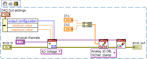
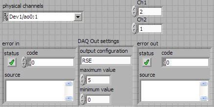
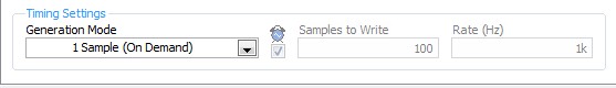
- Configure your analog output DAQ Assistant for output on the 9264 ao0, leave all default settings except for the generation Mode, you should change it to 1 sample (on request).
- Configure your analog input DAQ Assistant enter ai18, keep all the default settings again except for sync settings, which should resemble the following:
- Your drawing should look like this:
If you do this and you encounter problems with your sensor or its response after the datasheet (or at least the manufacturer and part number), and I'll look into it further.
- Configure your analog output DAQ Assistant for output on the 9264 ao0, leave all default settings except for the generation Mode, you should change it to 1 sample (on request).
-
How to find duplicates of a field value? For example - in a field, I have values like {123,345,346,123}, now I want to remove the duplicate value in the field so that my output looks like {123,345,346}
If it's an array you want to deduplicate then here is a script [for use in the Script Processor] I prepared earlier:
var result = new Array();
var added = new Object();
If (input1 [0]! = null)
{
for (var i = 0; i)< input1[0].length;="">
{
var point = input1 [0] [i];
If (! added [item])
{
added [item] = 1;
result [result. Length] = item;
}
}
}
Output 1 = result;
Kind regards
Nick
-
stop propperly generation of continuous signals (analog)
Hello
I want to generate a continuous wave-output analog (sine, for example) using NI-Daqmx. The example program in http://www.ni.com/example/29872/en/ works very well and does everything I want, but there are two problems:
(1) I want to count the number of waveform periods that are executed.
(2) if I press the stop button (or another event occurs), the program should not interrupt the generation of signals anywhere. It should complete the last period and than stop running.
I tried to solve this problem in timing the loop while I have exactly one period per loop. It works very well for small frequencies, but for higher frequencies (for example 100 Hz - 1000 Hz) not more

A second method used ends generation (always generate a period in a loop). But with this method there is an another serious proplem: if I make higher frequencies (for example 100 Hz or more) the loop requires too much time and the signal isn't continuous more because there is a short break between each period.
I am new to LabVIEW, could find a solution so far and would be very happy if someone could help me with this :-)
The key step is to make sure that the stop button is not connected to stop your loop. In a 'simple' control system, there is a single loop, and the stop button (and everything else!) lives inside the loop. When you press Stop, if it is connected to the loop Stop, everything stops.
What you want is for the Stop button to report a condition, namely 'Stop at the end of the current cycle'. If you generate data of a point at a time, you should be able to tell (by looking at the phase of the signal) when you are at the end. One thing you could do would be to ask (for each iteration of the loop) "I am the end cycle, i.e. the Phase 0? If this is true, and the Stop button is pressed, Stop.
BS
Maybe you are looking for
-
Mac software cleaner advertising
Hi I keep getting this pop up to any body can it me it's an Apple product
-
HP cartridges: rewards for the used ink cartridges
who issues coupons rewards for turned in used HP ink cartridges at Staples?
-
Find music and play music in their own country
I copied the music of my c: drive of the slate of more than 7. How can I find the music? On my desk I have two icons: music and MXPlayer player. What are the steps to find and play music. Ditto for ebooks Thank you all.
-
I have an old Dell computer with Windows XP Prof installed including service pack 1. All of a sudden, I'm not able to use my password to connect. I'm sure that the password is typed correctly, but it does not accept it. Now what? original title: pass
-
I couldn't install the software of my officejet pro 8610 on 3 of my computers portable windows 10. I contacted HP support, and we have tried to install the software nothing works. I went to the 2nd level and they have worked trying to activate the