Linear encoder
Hi all
I want to record the signal position (rotation). If there are 1024 pulses per revolution, I want that signal position to increase fitted (1023,1024, 1025...). I use linear encoder or angular encoder (of DAQmx creat virtual channel).
I use NEITHER-9411.
Thank you!
Tags: NI Software
Similar Questions
-
Why the my linear encoder is only tend to read negative?
I have a linear encoder, that I am using with one NOR cDAQ 9184 & 9401. I basically used the example of linear encoder, I found here on the website of OR, however, when I run the program I find that measuring only in one direction is the precise movement of reading. By this I mean when my encoder moves upward (actually my camera moves down and the encoder is fixed) I can move properly, but when moving in the opposite direction I'm away. I'm not a linear sum, very different each time. Sometimes when the movement he began first almost looks resets the unit to its original position (0 "), but I am helpless as to why. Does anyone have an idea on how to remedy this situation?
I'm pretty confident I have things wired properly while this same configuration/encoder reads correctly in MAX, see the second screenshot.
Well it seems that the question was much easier than I thought. Of course, I'm a newbie to this, but I think that most of the confusion was due to the lack of detailed information. None of the documents of OR really explained me the option counts two impulses, more the X 4 and documentation of the mentioned readhead times count four. However, after receiving no not any solid solution, I started completely over and tried all the options I had along the way. In short, my solution was to simply what I posted in my screenshot, but simply change the X 4 option for counting of pulses two option.
-
How constantly sample meter signal for quadrature linear encoder
Hi all
Trying to permanently change value of Schneeberger linear encoder quadrature at certain frequency as 10 Hz of the sample and the output to the text file. Everything I choose in the external clock that I can't run the DAQ assistant. No one knows how to fix? I don't know what kind of clock can be used.
I have read a few replies that ppl would connect to an another sample clock in parallel with the meter channel. But I don't know what is the principle of operation of this method.
I spent already as 10hours on it. Could someone tell me that some information?
Looking forwad to your help! Thank you very much!
Best regards
George
Hi George,.
You'll want to use the DAQmx API rather than the DAQ Assistant.
The task of the encoder itself would look like this. You need not use the trigger options.
The problem is that you will need to generate a clock from another source that the card is unable to generate examples of clock counter directly. The simplest is probably to use the second counter. Here is an example showing how to use a meter to output as a sample clock (although the example shows the analog inputs, simply replace the task of analog input with the task of the encoder shown in the previous example, I linked).
So, you would use a counter (say ctr0) for the task of the encoder, and then the other (ctr1) meter for the generation of sample clock. You must specify your task of encoder using the InternalOutput of ctr1 as the sample clock (if the internal counter output appear in the drop-down menu, click with the right button on the terminal and select the e/s name filtering > include Advanced terminals). Start the encoder task before the output task (although given that both are running continuous it doesn't really matter that much).
In addition, 10 Hz is not too fast. If the exact date is not as important and the above seems a little overwhelming, it might be easier for you to just run a loop of 100ms clocked by the software from example like this. Note that the exact time loop pourrait will vary from cycle to cycle, so this method is not very good if you use sampled data to perform calculations of rates.
Best regards
-
Linear encoder and configure logging
Hi all
I am currently using a surfboard with LV2010 M Series PCI-6280.
I have a linear encoder in X 4 mode connected to the counter 0 and I was wondering if it is possible to spread the values on the counter because it keeps track of the distance in a file TDMS using 'DAQmx Configure Logging'. I tried this using MAX to set this, but it doesn't seem to work, so I wonder if it is still possible that I couldn't find anything online about it.
Thank you
Lester
Hi Lester,.
My apologies, I tried on another Committee. It can work with yours, as well. There is an example of a task of counter in the buffer that should allow you to save the data by adding in the Configure logging VI as we did before.
Open LabVIEW and select help > find examples... it will open the Finder of the example. In the Finder of the example, expand folders to get to the input and output material > DAQmx > Counter measures > County Digital events > County Digital events-buffer-meter-Ext Clk.vi
Put the meter right channel and channel PFI in the controls, and then run the VI to see what he does. Then you can change the schema to add the configuration Logging VI (just as before) and rerun the VI. You will find yourself with a TDMS log saved to the path that wire you in the logging VI configures.
I hope this helps.
Kind regards
Daniel H.
-
I want to simulate linear incremental encoder to Labview FPGA
Hi all
I use the card to FPGA OR 7851-R to simulate incremental linear encoder. I want to generate the impetus A and B of the map to simulate the features of linear incremental encoder according to the distance.
I don't know how to do so please help me for the same thing.
Have you tried to write any code yet? Why not start by generating just the channel has? It is a question of turning a digital channel on and off at regular intervals - a PWM with duty cycle of 50%. I think you can find examples of generation PWM is included with LabVIEW or on this forum. Then, to generate channel B, you must enter the code, but with the starting point offset by 1/4 of the period. Once it works, simply limit the number of periods of release based on the "journey".
Look through the examples, write code and see how far you can get. When you get stuck, view the code that you have written on this subject and explain the problem.
-
High speed continuous measurement of encoder with sampling frequency of 1 kHz
I am able at all times the position of a linear encoder using a PCI-6602 counter card, and I need to know how to set up so that the counter rotating at high speed, but the data is inserted into the buffer at a frequency of 1 kHz. I am able suddenly to a hydraulic cylinder, and I am not concerned about the event recording to high frequency except to the extent where they throw off the number considerably if the equipment does not run fast enough to detect all the impulses of the encoder.
Now, I think is that the external sample clock signal control (routed internal pulse output counter) time rate whereby the equipment detects the impulses of the encoder and the rate at which it inserts data into the buffer. With a pulse 100 per inch encoder and a sampling frequency of 1 kHz, the extended final position of the cylinder is turned off by +/-0.15 inches, which is unacceptable.
I need calculate a speed of this information, so I prefer not to use software timed sampling to control this (it's more difficult programming for other reasons as well - several asynchronous measures). Any ideas on how to configure the hardware to count faster than the speed at which she inserts counties in the buffer?
OK, you're clearly on the right track here, so I will focus on some details.
1. How do you know that the +/-0.15 "differences are * measurement error rather than * error of movement? Why wouldn't be an accurate measure and a proposal which can vary slightly from the nominal value?
2. I wonder some all electric noise and defects that may produce false edges. The fact that the behavior was better by using a sampling rate limited (200 kHz) in the digital inputs may be that some of these flaws were so short that they were never captured.
I did a ton of work with the Commission to 6602 encoder and I can certainly confirm that count equipment is sensitive to the edges in a few tens of MHz. (I know its 80 MHz for edge counting, but I think I remember that it can be of the order of 20 to 40 MHz to accommodate the time of signal propagation extra of the quadrature decoding circuit).
A small point of clarification. You're talking about the speed at which the meter "works to. The value of count is a register whose value is changed completely by the circuit, * independent * of the sampling frequency. If you enjoy with material-clocked County in memory buffer or interrogation of software without buffer not a bit for circuits that increments / decrements the value of the counter register. (In other words, I am completely convinced that you would get commensurate with position end even if you took only 1 sample software-polled after the end of the move instead of sampling at 1 kHz all the way through.)
So, if the value of the counter is disabled, it is because the circuit detects producers of County of the edges that shouldn't be there. Something you can try is to set up digital debounce filter for input lines of the PFI corresponding to the encoder Source inputs and to the.
-Kevin P.
-
Count the edges of the 2 signals TTL (Heidenhain linear scale)
Hi all
This is my first post here. :-)
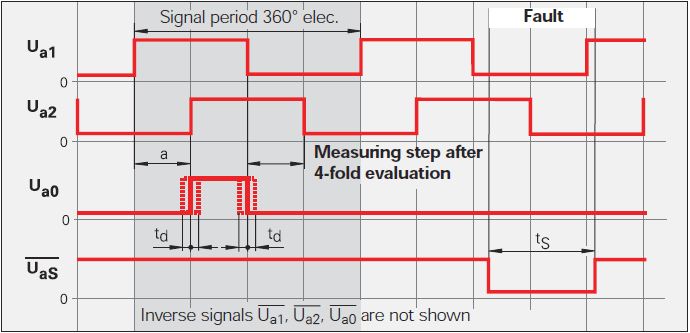
Currently, I'm doing a VI to be used with a linear scale. The linear scale gives 2 TTL signals that have an offset of 90 °. The change in distance of the linear scale is given by counting the fronts and edges of the two signals. See the following image: Ua1 is signal 1 and signal 2 Ua2. You can ignore the other signals.
Now, I want to count the 4 edges in order to translate the 2 signals in the distance. This means that I need advanced two counters for Rising-rising, Rising-Falling Falling Falling, falling on the rise for 2 signals. I tried to do 4 points two counters in LabVIEW but that of course does not work, because an acquisition of data can access the card TTL or I did it wrong.
Once I have to handle this, I also want to understand the meaning.
My card TTL: NI 9402
My electronic Heidenhain interface: 100 IBV (http://www.heidenhain.com/fileadmin/pdb/media/img/598_160-23.pdf - also at the origin of the image)
Hardware configuration: linear scale-> IBV (Elektronic Interface)-> NI 9402-> LabVIEW
Signals: Analog 3-> 3 TTL-> OR 9402
I hope I do not double post. Any help would be greatly appreciated.
I used Heidenhain linear scales in many applications.
As stated in the previous post, the output of your balance is as a quadrature encoder. Therefore, you must use an entry of the DAQ card counter to measure the position of the scale.
The desired X 4 mode is done by the meter itself (not possible with some old maps of OR).
As starting point, see measure angular Position.vi that comes with examples of LabVIEW. On your linear scale, change the type of the polymorphic DAQmx create channel VI CI linear encoder and etiquette of pulses per revolution at a Distance by pulse.
Feel free to post back if you need further assistance.
-
Hello, this is a simulation using Labview 2011 years USB-6009.
the table contains X (angle of encoder incremental counting rising edges) and Y (distance of linear encoder simulated with random numbers).
The wheel is gradual and must be zero so every 360 points (X), the XY graph must be refreshed to show the last values 0-360.Nickname:
If count > 360 then set I = 0 and turn, write another 0-360 array and record all comparison tablesQuestion:
Is a function box to use or two nested for loops with 2 counters, one up to 360 and the other until the overall value?In normal programming, I would divide the total number of 360, if the remainder is zero, then I would reset the meter I have zero, but I don't know how to "translate" in Labview.
Thanks for the suggestionsGeorge
Some points to note:
feanorou wrote:
Nickname:
If count > 360 then set I = 0 and turn, write another 0-360 array and record all comparison tablesSince 360 = 0 the code must be: If count > = 360... 0-359, 9-small but mean difference

The function you're looking for is the
Quotient and remainder function
Have the Palette: Digital features
Request: Basic package
Calculates the whole quotient and the rest of the entries.
Another useful thing is the shift register (see the tutorial of LabVIEW) you can use in your loop to keep a tachometer. Every time that Exchange (increase) you can save the update etc.
-
Sinusoidal linear encoders Heidenhain 11 (micro) App and USB-6009
Hello, I need to read the two linear encoder sinusoidal signals App 11 Heidenhain (micro), described on page 37: http://www.heidenhain.com/fileadmin/pdb/media/img/208_945-28.pdf
I have been using a standard oscilloscope and merged the two signals on a X - Y axes screen two, to display a circle to inspect if the glass scale is OK.
If the glass scale is OK, then the circle is relatively stable in size and position when you move the receiver along the scale.
Now, I would do the same test with a USB-6009. Is this possible? The two signals should be treated as current input analog? In this case is 11 specifications USB 6009 operator?
Thank you
Luke
-
PD controller - expression of linear speed
I have a PD position controller in LabVIEW (force) current send commands to an actuator linear servotube via an amplifier. So far, I tried to read the data of position with a potentiometer linear and taking a derivative to find the speed (for the term D PD). The system seems more stable with proportional control only. It makes sense after reading in "Modern control theory" Ogata this potentiometer signal is not suitable for differentiation because of the noise it produces. Questions: What are my options? Is to differentiate an equally problematic linear encoder signal?
Thank you
Maciek
Maciek,
move to RT should translate into a system behavior much better and tuning should become easier.
To increase the distance for the calculation of derivative is not really comparable to the use of a filter. As you have already said, filters add their own dynamics to the system, especially if you use higher order filters.
Jochen
-
By train and failing to carry out measures of speed
Can someone explain to me how the linear speed CI module is supposed to work? I tried with no successt for a while to use it to take measures to speed by using a meter. I use a card NI 9411 digital input to accept a signal from a radar system which shows a maximum speed measured as a frequency (which is just working at a rising every 0.176 inches moved).
Whenever I run VI I get an error in the module create channel which is as follows:
Code:-200431
Source: DAQmx create channel (CI-linear velocity) .vi:2530001
Property: CI. MeasType
asked the value: Speed: Linear encoder
Possible values: Frequency, period, pulse width, period of Semi, separation of the two sides, pulse frequency, pulse, Pulse ticks, Position: angular encoder, Position: linear encoder, edges of CountyThe task name: _unnamedTask<6>
That, on a subject similar, is there any where a document that lists the module chassis DAQ and DAQmx measurement compatibility? Because I do not find that documented anywhere it's obvious...
Well so be it... I finally found a document that lists the compatibility of type of measure and appearently the only module able to do using the virtual channel of speed measurement is the 9361 OR...
-
Hi all.
I work with an application that is count the pulses of an encoder hollow shaft renco to measure the distance traveled on a platform single axis powered by a ball screw and controlled by an engine step by step. The encoder is mounted at the opposite end of the motor directly to the ball screws.
That said encoder has 100 impulses per revolution and at the moment im using only 1 channel on its release to make the count. I use the channel of single window on a DAQ 6008 real counting down.
Here's my problem.
When I run the engine at a moderate speed and measure count pulses from a full trip on the axis I get 8200 impulses. If I reverse the engine now and bring it back at the same speed, the full trip will give the same 8200 impulses which is exactly what I want. However, if I run the motor at extremely slow speeds the same 8200 impulses correspond to only 3 quarters of the race on the same axis.
My hypothesis is that at top speed the DAQ 6008 lacks a large number of charges. I am correct in this assumption? I will soon have access to a DAQ 6211. This will provide a more reliable metering device?.
Thanks in advance guys. I'd appreciate comments.
It is just as likely (if not more) that you are picking up additional indictments at the slower speed - you can confirm enough easily by calculating how many pulses to be emitted during the movement of the platform to the desired distance.
The signal directly from a quadrature encoder can be quite noisy. The 6008 is only able to edge simple counting, so no noise on a front amount could lead on Board being counted more than once.
The 6211 supports a specific type of channel linear encoder, which configures the meter to use both signals A and B of the encoder. In this mode, the meter requires alternating the edges of A and B to continue incrementing, which means a noisy transition will always only picked up like an edge.
In case you do not have access to both A and B signals (or if the encoder is particularly noisy for some reason any and produced false edges in the middle of a period of high/low), the 6211 also supports filters PFI (link pdf Manual of use).
Best regards
-
Set up connection VI start and stop without losing or deleting data
Hello
I currently use a PCI-6280 M-series and a card PCI-6601 of counter measurements on Labview 2010.
I have 3 tasks implemented, 2 tasks of linear encoder on the 6601 counter and 1 analog input task with 4 inputs x on my 6280. All of these are timed with a counter on the 6601 through a RTSI line.
All of these tasks, I have a similar setup as the picture in http://zone.ni.com/devzone/cda/tut/p/id/9574 except that they are all set up as only "Log" and "create/replace" for the logging.vi configuration file.
Because I want to have the encoders permanently locate my position, I never "stop" the tasks of meter. However, I need to use the data acquired after each trip along the way to get and process location and subsequent analogue input data points I have. What I did, I would be 'stop.vi' my clock on the counter sample, and then open the PDM file, read the file PDM, get the table from there, close the PDM file, then "run.vi" the clock on the counter sample. However, I found when I stop the sample clock, not ALL data points have been listened to in the file.
For example, say I move my cart to 100mm to the right during recording, then stop the sample clock, get the PDM file table, find the size of this table called 'X' for future use. Then I get the ramasseherbe on the origin WITHOUT restarting the clock. THEN I start the sample clock and move from 100mm to the left. After that, I once again, stop the sample clock and get data from my file tdms starting at the offset of reading on "X + 1". I EXPECT that this table SHOULD start at 0 then go to the 100 mm to the left. However, what it does, is that I see the data begin at 100mm from the right for a few data points, then GOES to 0, then moves to the left as planned.
I propose this means that when I stop the sample clock, data from meters (stamp?) not all were listened to the tdms file yet, and when I start the clock, the rest becomes she dumped. Here, I'm confused because I thought that 'configure logging.vi' stream directly in the file without a buffer.
I was wondering if I'm doing something wrong, wait bad things, and if there is a way to apply what I want. As in, is there a way to dump data remaning in the "buffer" (I tried the tdms vi flower, but that didn't work and I didn't think it was relevant) after I stop the clock or something like that, or is my implementation to offshore competely.
Thanks for reading,
Lester
PS. have a way to read the most recent point counters would be great also. However, whenever I put the offset or relative to the most recent, it is said that I can't do during indexing, even if I saw a community post saying that it works with analog inputs. This is perhaps off topic, but yes, now I'm just trying to get the tables of PDM works, thank YOU!
-
What module/card is necessary?
Hello
Please let me know which module is required to receive the signal of the following:
1, Magnetrostrictive Position sensors, Temposonics-RD4 position sensor, measuring range 25-5000mmm for hydraulic cylinders
2. linear encoder, unidentifiedThe VI you posted is designed to work with the encoders with output logic level quadrature. If your linear encoder has outputs in this format, it should work.
Position sensor has a 10 V output. Use any device analog input with a 10 V input range to read your position. The 6251 should be good for this. Once you have the power you need to resize it to represent the distance. The transducer seems to be linear, so you can probably use a y = m * x + b of linear scale. If your reference position y = 0, you only scaling of the slope.
Lynn
-
Hello
I use LabVIEW 2014 on 64-bit Windows to acquire data of moving a digital coder as follows: linear encoder Renishaw--> NOR 9411 digital in--> cDAQ - 9174--> Windows machine.
I have a VI that records moving to 5000 Hz. He was works well for weeks, but suddenly, change value (i.e. the County) remains stuck to zero any movement there.
Trip data are also used in a feedback SoftMotion loop. Which works very well. I use same SoftMotion commands to create a history of travel, that looks right (this story of displacement is limited low frequency of activation by SoftMotion nature so I created this second way to measure travel to high frequency). Point being, I am convinced that the linear encoder works fine.
I am extremely confused because I have not changed anything of substance I can think. I move the cDAQ9174 to a different os of USB cable I started with the assumption that I had screwed up connectivity somewhere in hardware. The cDAQ-9174 and NEITHER 9411 times pass Self Test NI MAX. I checked the relevant cable continuity by pin and it is fine. Then I started to try to get more information on the value of the counter. I have a number of versions of this VI and they all report that the meter is flatline to zero any movement there is in the system. I ran the VI in run mode of looking for clues and I noticed something that seems a little weird, at least for me. The meter is identified as cDAQ1 / _ctr *. Does anyone know what this means?
Attached is the VI screenshots with and without highlighting on execution in case someone sees something in there that I'm missing.
Thank you
John
Thanks for your help. I can't exactly say I solved this problem, but the problem disappeared. Any changes I made to the wiring and then repeated to them, I reversed and all of a sudden it worked again so he must have had a problem connecting somewhere along the line. Thanks for explaining the * thing, good to know that it was a Kipper.
John
Maybe you are looking for
-
W520 Type 4270... Tabook.pdf question?
Someone at - it an older tabook.pdf which lists the Type 4270 W520 (or a link to an older version)? __________________________________
-
Switch 10: Keyboard dropping characters
If I type for about 30 seconds, when I start again the first character is always deleted. Looks like the keyboard is in standby mode. On the screen keyboard is fine as is the full-size USB, one I use at home. I downloaded and installed all the latest
-
Windows 7 Professional 32 bit and Media player 12 play DVD files on the hard disk of the PC.
I want to be able to read dvd files (vob files) with media player 12 by selecting the folder and then just click on play like no other product like power dvd or nero showtime, but I don't understand how to do this with wmp12. Also why can I not add
-
No no its inspiron 15-3542 ubuntu 12.04 but speaker...
No problem with his helmet Tested speakers and works well under dell tests Followed all the recommended forums answers but still speakers are silent under ubuntu 12.04!
-
My profile is no longer load when you connect with Vista.
I tried a restore of the system - no change. Lost Outlook, email, contacts, desktop and icons load upward with a standard desktop computer. What can I do? I need help please!