linear measurement of the vector line
This one is probably directly in my face. As if the vector line is a piece of string and I reached the chain to make a straight line, Illustrator there a way to determine the length of the line between two points of selection? I deal with complex curves, estimate a retrofit for a vintage sign.
Thank you!
1. context menu for document info Palette: turn on selection only.
2. menu of driving the information Palette document: turn on the objects.
3. Select the path. The range of information to Document displays its length.
Suppose that you have a recent version. I don't remember if it was added in CS1, CS2 or CS2. ALWAYS indicate what version you use.
JET
Tags: Illustrator
Similar Questions
-
Is there a way to make the vector lines (Path) more Visible in Photoshop CC on OSX?
Is there a way to make the vector lines (Path) more Visible in Photoshop CC on OSX? Just passed from the CS6 in the CC, and it is very difficult to see when they are in fact seen visible.
Apart from excellent advice from Terri, there is no way to really change how the paths appear - nevermind, I could use those more visible as well.
-
During the measurement of the vectors in CS6, it changes the path of my draw randomly.
I have a picture of the present.

What can I do?
Align is enabled for the pixel grid paper? Look in the transformation Panel and if this is the case, clear the check box.
-
Photoshop CS6 vector line tool UI issues
I'm running 13.0.1 right now and am blocked by the tool of UX line. The problem is that even if you feel that you draw a line, you actually draw a box.
Follow these steps 13.0.1 running x 64:
- Create a new doc
- Select the vector line tool
- Type in a width of line (for example: 20px)
- Draw your line
- Note that the line is always weight of 1px.
Of course, after much fiddling around you realize you have to set the FILL of your race, color, NO line, then specify the WEIGHT on the far right of the control bar.
This is not really the right UX to draw lines, especially if you come any other vector drawing environment.
Pen tool will draw lines with adjustable race. Shape mode, the value none Fill tool, set the stroke alignment to centered in the menu drop-down shown. Click on the points without slipping, if not a curve will be created. Hold the SHIFT key to constrain the horizontal/vertical. Press ESC or enter or select another tool to end a line. Properties stroke remains editable as long as the shape layer is not rasterized.

-
Hello!
Is it possible to convert a trace made with the Brush tool a blob in a simple brush trace (a simple vector line - not two lines with a filling in between)? Thank you very much for your help!
No, I don't think.
-
A3 landscape artboard. When the zoom is less than 100%. the appearance of the work (lines) in staircase, I can tell this resolution because something I have to zoom and it disappears. I understand the difference between vector and raster so... this kind of problem is like when you zoom too in an image and it becomes pixelated... but otherwise...! I have a macbook pro 2012 model, the retina. is my screen resolution. I thought that the apple screen product meet good standards of adobe creative products... Reviews
Check if the switch between the GPU and CPU makes a difference: Cmd E
Or turn in the preferences: GPU performance.
-
Line of text well rolled on top of the vector form
Hello!
I know how to create a winding line of text using the pen and text attachment to the Path command. It's easy. BUT... What if I want to PLACE this text a little winding on a shape vector real, say an ellipse. What should be my workflow? As I do is... I first create a vector object, for example, ellipse. Then I create a text. Can I use the same way I described above (ie. Select two things with the SHIFT key then go to the text of attachment to the path). But the problem is... The vector object disappears! And all I have on the contrary is just a text well rolled on top where there USED to be the vector object.
But I like to keep BOTH, the text and the object together. How this can be done?Duplicate your curvy object and then attach the text to the top in the list of layers.
-
History of the vector graphic bike in Photoshop 5.0LE pdf on CD User Guide
Hello. I recently bought a new copy of Photoshop 5.0LE and saw that she had a pdf of the User Guide on the CD-ROM. I have been fascinated by the graphic vector image of a bike on page 24 of the pdf User Guide. When I opened this page in Illustrator and looked at the information in the file-> advanced-> properties of the PDF, it read that the creator of the pdf User Guide was someone by the name of "nhirooka" in 1998 and that it has been created in FrameMaker 5.5, that I recently bought and learn.
The only thing I have still yet to understand is how the graphics of the bicycle was created? It was in an older version of Illustrator? One thing that is interesting about the picture is, it is tinged with several created manually linear and radial gradients (i.e. concentric vector or border-touch rectangles, circles each filled with a slightly different shade of gray). Now it's a lot of work that went into creating this vector image!
There are differences in features between the bike on the page raster image and the image of bicycle vector (for example, no crutch in vector image, lacing of the rays is totally different). Do you think that the image of the bicycle was created by tracing high resolution photo (s) of the bicycle? Or were the measurements in directly bicycle parts and then did something like Autocad first before importing into Illustrator for coloring/shading? I'm puzzled.
In addition, I can't figure out how to get the vector image of bicycle in FrameMaker 5.5 without some kind of distortion. Maybe I need the right older version of Illustrator for this? Exactly what versions of Illustrator 5.5 FrameMaker accept vector images directly (i.e. drag / move)? I have CS3 and FM5.5 does NOT accept images of her.
How the vector image of bicycle was created and then inserted into a document of FrameMaker5.5? Is what I want to know. Does anyone know the history of this?
Regarding the placement of the vectors from illustrator, when you save as or eps, the option dialog box has a drop down menu to choose an older version of got it or eps, that should work.
I've never used FrameMaker, but some old page layout programs would display a tiff in the screen image but pass the EPS to the printer. That's why you have the possibility to integrate a tiff image in an eps file.
-
Conversion of a Signature TIFF in vector lines
I scanned my signature in my computer in TIFF format. Then, I edited and cleaned in Photoshop. Then I placed in Illustrator and transformed into a vector file. However, the problem with this is that traces the perimeter of the signature and not down the middle of the letter strokes as there would be if I had done in Illustrator. Is it possible that I can still get there?
I've just converted to a tiff file becuas vector lines have been transformed into double lines in the scene. No idea why this was happening or the other. I have just expanded their enough that he hid any gaps and then converted to a tiff file to have another shot at him. Would much rather work with a single line of.
MrDilly,
When you draw a raster image, you will get the paths defining sets (or almost) identically colored pixels, then you will get the fill/nostroke railways.
What you want are vascular accident brain/nofill paths. If your original features have different widths, you need to use artistic forms or the width tool to reproduce.
To get each STROKE/nofill path, try this, using the relevant part of the image scanned/cleaned:
(1) with the Scssors tool, cut the race at the ends so that you get two tracks open representative or the other side of the race to be (this will also be cut it off from the rest of the signature if necessary);
(2) object > blend Options, check the box Orientation > align on the path and set the spacing > measures specified for 1;
(3) object > mix > do and object > blend > expand, then object > dissociate; you have now the backbone of the race and the bounaries;
(4) adjust the weight of the race to have the race reach the limits, either by using a Brush Art (created horizontally at any horizontal scale) or the width tool and repeat with distributions different widths until you're there.
With the Art Brush, you can reproduce irregularities and asymmetries, also at the ends, finding (more) faithfully the real signature.
-
Matrix - vector lines and columns
M1 (3,2) gives the element of line 3, column 2
M1 (2) gives the second row of a matrix (as a vector line)
Is there a way to return a column (other than transpose, store again and using the method above on the transposed matrix)?
Tim Wessman wrote:
Assuming that first here...
Col(M1,1)
Row(M1,1)
@ Tim,.
As Mmmm - created a post on the 39gii and commented on a post on the 39gii, this one is perhaps more likely to be on the 39gii?
I think that your presumption re - expresses my presumption that the 39gii becomes brother forgot the premium?
@ Mmmm.
Try M1 (-c), where C is desired column number. For example M1(-2) for column 2.
-
Measurement of the hysteresis with metal plate
Hi all. I have the task of understanding. I want to measure the hysteresis of elastic coupling. To the couple measure I two strain gages on 90 degrees (NI 9237 bridge half, II). After calculation, I now have the couple. In the other hand I measure angle of rotation of the motor with a metal plate with 52 teeth (gear). Angle of rotation I use input digital OR 9401. Hysteresis of bild, now I must on each tooth torque couted. I tried the example Multi - multifunction - Ctr Retrigg a generation sample clock Pulse Train HAVE but still graf give me the straight line. Can someone help me with this? Are there more better example for me, or clips in internet to show me how to do? Thanks before.
This is this case, the problem may be, the data acquisition card cannot rearm the fast enough triger either acquisition takes too long.
In the configuration of the screenshot I see you want to acquire 100 samples at 1 kHz. This means that each acquisition will be at least 100ms which might be too long for your application. NEITHER 9237 supports a maximum rate of 50 kHz, so my first sugestion would be to simply increase the sampling rate and see if it helps.
-
I only need a port of each line for the use of the PFI and want to use the rest for the digital I/o. Before you complete the design of the circuit and test it myself, I would like to check it out. I can't find the answer in the textbooks, either.
Thank you
Ben
Hello Ben,
If you use all the PFI lines you can use the rest as DI/O. PFI0, 1, 2, 3, 8, 9, 10, 11 are entered digital and PFI 4,5,6,7,12,13,14,15 outputs digital. Another technique you can use is to create a spot on the measurement and Automation Explorer, if it allows you to create it, then it is possible.
Best regards
-
Why do I get error "20019 ADC conversion failed" with my pci-6143, when I try to use the DIO lines?
I am tyring to use one of the digital input lines on my PIC-6143 to go to the connection "enable" on the "write to file measure" vi. I have two cards PCI-6143 acquiring analog signals of 8 channels per step, plus I have a digital DAQ assistant to the sample line of DIO 2 on one of the cards. Normally I can start and stop recording using a signal of 5V to the DIO port several times until I get the error.
Strangely, when I use a simple Boolean "Record" button at the port of the 'writing on a file as' enable vi, I never get this ADC error no matter how many times I press the button.
I am including a screenshot of the error.
Thank you
Chris
Please ignore this message. The whole issue has been resolved by copying and pasting the VI in a new file in VI. The new file ran perfectly. Must have been a compilation of LabView or something error.
-
Measures with the date Conference
Hello
I have to make an application, as part of my end of study project, which allows to calculate heat flow. Pour this, I have data measured with thermocouples. These data are stored on a data recorder that record these data on a .txt, .xls or .csv file (it is to be chosen by user).
I'm not very chiseled with LabVIEW.
In a Prime Minister, I tried to read the .txt file data. I can read the 1st line as I wish but not others.
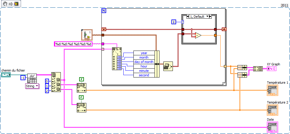
So I decided to work with a .xls file. The temperatures Conference goes smoothly. For time is the date, it's more complicated. Indeed, I would like to USE date and time corresponding to each measure to plot a graph XY with the date and time X and Y the temperature of the thermocouple.
Kind regards
Here's an example (VI from LV2011 but attached VI en LV2010) made on the basis of your code. Comment by watch it extract the news date and time of the string and generate the the from graph XY time in seconds in X. realized very quickly, it is without doubt room for improvement but you will serve as a basis for work at least.
To define 'Structure box' serving at first as far as being 0 and calculate relative time to the following samples. Thus the x-axis of the graph starts at 0.
My time is short, I renounce other comments but I happy to answer specific questions.
-
How to display the grid lines? -Adobe Acrobat Reader DC
Help!
Please can someone guide me through the display of the grid lines on a PDF using Adobe Acrobat Reader DC?
I recently installed this program and am aware that there is a way to overlay a grid on the documents, but can't seem to access this feature?
Please see screen capture below where I think I should be able to access to this: view > Show/Hide > rules & grills > grid?
For now, I see that thicknesses.

NOTE: I am not referring to the transparency grid - I need the overlay of the grid, to help measure the elements of the document (from a design perspective).
Thank you


It is available in Adobe Acrobat format, not Acrobat Reader.


Maybe you are looking for
-
So I rented a movie on my iPad 2 Air and the film shows that downloaded, but the movie does not start. It just closes even after I sync to iTunes. My computer is not yet show that rented, but it is on my iPad. What should I do?
-
Projector is not capable to connect with Satellite U300 - 151 Fn + F5 works not
Hi alllast Sunday, I tried to connect my laptop with projector Panasonic and pressed Fn + F5 keys, but of no use it was not showing anything on the projector...Please tell me precedure step by step to solve this problem. Thank you and best wishes in
-
Y480: cannot install OneKey Recovery
Hi Please help,. I have lenovo i7 y480, runs in windows ultimate 32 bit I do not have the recovery disk Operating system is preinstalled My problem is there is no ONEKEY RECOVERY software installed in it and I really want to restore my y480 to factor
-
Original title: "System86.dll" I'm having a problem during the installation of 3D games in window 7 ultimate Error code is: System86.dll I was using Window 7 Ultimate for a while, before a few days ago, when I tried to install the game in 3D (prince
-
I have an acer laptop about a year ago, I put a username and password, but now that I want to use again, I forgot the password. How can I reset it so that I can get into my laptop?