measurement of signal of phase
I want to measure a signal in phase and out of phase, how do I set up a VI to measure them separately?
The phase of a signal linked to what?
For a measurement of phase, you must always a time reference (or a reference to another signal phase)
If you have a rude sine signal, you can try vi tone detection, the output is of amplitude and phase, so just calculate has and b (see complex number functions)
Or you use the FFT vi and get the bins already complex at frequencies which correspond to those you are looking for, if all goes well except if you match the input data (or do a bit of math more  , BTW is what makes detection of tone vi)
Tags: NI Software
Similar Questions
-
pulse width of measurement of signals generated by data acquisition
Finally, I would like to:
Start a counter pulse width measurement and the analog output at the same instant.
Stop the measurement with an external digital signal pulse width.My current plan is to use a digital output on the acquisition of data to synchronize a digital input and the start-up of the meter input. The digital input will be a trigger to start for the analog output. This works, except for the meter.
While trying to implement this, I tried a simple test to generate a digital pulse with the acquisition of data and wiring for counter inputs. It does not, even if it seems perfect to an oscilloscope. Then, without changing the software at all, I connect a function generator to my counter entries, and it measures pulse flawless widths.
I'm actually implemented it with a Python wrapper around the C DAQmx API, but I recreated in LabVIEW, and it has the same. VI attached. I have the latest drivers DAQmx.
Accidentally, I posted this in a forum for LabVIEW, as I managed to post with the account of a colleague. I think 2 ups live as this mandate to another post. I'm sorry. Former post is http://forums.ni.com/ni/board/message?board.id=170&message.id=389856.
Solution: I had to set the channel to counter with implicit synchronization. In addition, the sampsPerChanToAcquire must be at least 2, if not, there is an error. I still don't understand why it worked with a source of external impulse, however.
DAQmxCfgImplicitTiming (task_handle, DAQmx_Val_FiniteSamps, 2)
-
Is it possible to measure digital signals with devices of simulations?
The simulated device configuration is the following:
9174 chassis cDAQ (cDAQ1)
-9215 (cDAQ1Mod1) (analog in)
-9401 (cDAQ1Mod2) (digital i/o)
With a digital line (e.g., line 4), I create a single pulse
------^---------....
where the circumflex indicates the pulse short and simple.
Is it possible to use a digital line (for example, the line 0) in to measure it in the device simulated using a kind of direct/indirect routing? If so, how a set to the top of the digital input read task essentially read the output on line 4, internally?
Thank you.
N ° as the DAQmx help explains, you do not have this ability with a simulated device.
-
measurement of the phase of the signal
Hi all
I'm trying measureme the phase of the sine wave.
I produced sine waveform and give '' measure spectral '' VI express to measure the magnitude and phase. The block of spectral measure gives picture of the spectrum amplitude and phase with the difference in frequency of 1 Hz.
The input signal is 10 Hz sine wave. so I checked the 10th item in the table of phase and amplitude. I'm getting the right size. but I get different values for phase measurement
For example, if the input signal of 0 degrees phase shift, the spectral measure gives as-90 degree. If the input signal has the phase shift of 20 degrees, the measure blocks gives as-70 degrees.
I can't able to find that how to pass this phase-90 degree occurs.
Kindly help to solve. I thank in advance.
with respect,
Renaud V
Renaud V,
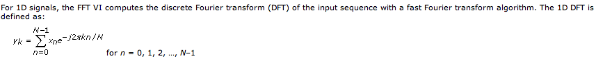
The spectral measurement VI uses the FFT internally. In the detailed help for the FFT, the following definition is displayed:
Note that exp(-j*2*pi*theta) = cos(2*pi*theta) - i * sin(2*pi*theta). This phase shift is defined in respect to the cosine, and non sine, explaining the 90-degree turn.
Lynn
-
determine the difference in phase between a reference signal and measure
Hello
I use a PXI-1000 b with two cards DAQ, PXI-6133 and I need to measure the difference in phase between a reference sinusoid, acquired on a map and an acquis of the sinusoid measured on the other card. So far, my idea is simply to acquire samples of N of these two signas as waveform data, then compare. My problem is that I see a way to extract the information from the relative phase. How would I do that? Is there a better way to achieve this end?
Hey GlenS
Check out this link. Use it a Subvi spend an entry as the data acquisition card entry and the other your reference wave. It should work.
Good luck

-laboratory
-
determine the angle of a complex signal phase
How can we determine/measure the amplitude and phase angle, separately, signal output complex in AWR in circuit level (schematic) design?
It depends on what you mean by complex 'signal': power, voltage or current? If it is a simulation of harmonic balance, you can use measures Pcomp, Vcomp and Icomp for value complex to a specific harmonic and choose 'Mag', 'Angle' (or "AngleU") as the modifier "complex" for the measure. This can be traced and then compared to what you are scanning. e.g. power, frequency, etc. If this does not answer your question, attach a copy of your project, or at least a photo; So we have some background.
-
Measurement of Phase difference of audio - learning how to set the reference
I'm trying to measure the difference in phase between two audio inputs. (Left and right channel of my sound card)
Both are free running 1 kHz audio samples that come in and out of phase.
When the samples are in phase, everything seems to work fine and shows no phase difference.
However once that signals start to emerge from the +-10deg phase the result keeps jumping around.
It seems to be the fact that it is changing the reference to determine the phase.
When I view the phase of the output of a channel is a sawtooth waveform, from 250deg and then wraps round to-110deg
What I want, it's an entry set to 0 degrees and see the other inputs of difference of phase against it.
Is there a way to give a signal as being the reference or another strategy?
Thanks in advance for any help.
PLEASE NOTE THAT THE acquire.jpg IS ACTUALLY THE VI.
It wouldn't download like the vi. Please rename extension to acquire.vi to see.
Finally managed to find the problem.
Red rooster, I tried to replace your entries simulated with audio inputs card his real world and things turned out horribly.
It doesn't seem to be a translation between the two. (Perhaps because of my understanding of Labview garbage)
LabVIEW uses the internal reference of the DAQ cards in order to make phase measures.
That's what all use the phase VI of measure and which lack of cards not NI - DAQ.
That's what I thought that missed me first place but there's no way I can see simulations your own.
To work around the problem, I used zero crossing detectors in order to compare the time ahead or lagging behind the benchmark for the calculation of phase.
I got the core of the detector from somewhere on the forum but have lost the actual page. (my apologies to the author who deserves the credit)
Anyway, hope this hepls someone.
-
Frequency measurement and phase of a square wave using to extract the information of your unique vi
Hi all
I'm trying to measure the frequency and phase of a square wave from a data acquisition card using vi retrieves your unique information. So far, the frequency can be measured precisely, but there are a few problems with the measurement of phase.
I have attached a sample program here. I generate the wave square using Square Wave PtByPt vi. The default sample size is 1000. When I put the frequency = 7.43, phase = 80, the frequency can be measured precisely, but the phase is completely. Is there something wrong with my program?
Thank you very much for your help.
Best regards
A square wave is not a single signal ;-)
If you have a square wave use the edges to make measurements.
-
frequency of measurement of digital random signal
Hi all.
I want to measure the frequency of the signal. This value will be sent to any other device to vibrate the vibrator according to the value.
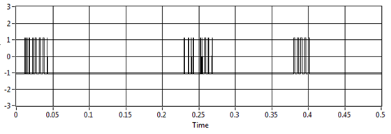
For example, I want to measure this signal:
I try to use your vi and extract single signal measure vi, but the result is not fair, for example, if I have no pulse on the graph the result is 11, 5 Hz (it should be 0 Hz)
I use assistant NI USB-6210 and acquisition of data to get the data from the sensor
Laughing out loud! All that motivates you... I don't see attachment. I commented on the block diagram on the vi attached which may help. What you can do in your data acquisition program, use is get the queue with the name of data. Then take the waveform of the DAQ assistant and use waveform components get to retrieve the values of the real signal (-1 to 1). Now use a loop with automatic indexing on table of signal and inside use enqueue to place each value of the signal on the data queue. In the joint programme filter, you can either copy the lower node in your program for the acquisition of data, or remove the loop of high signal generation and run them in parallel. The nice thing about the queues is that they can transport data between different vi on the same computer that the name is the same. If you want to do something with the frequency measures, while you can use a different queue for buffering of the data out of the loop of measure.
Good luck!
-
Can I use 6115 measure DC or low frequency signal
I use 6115 OR data acquisition if put singnal superior to 100 Hz, the result is very good.
But if the frequency below 10 Hz, the result is not fair.
I try MAE and choose the DC coupling mode, it still can not measure DC signal.
What can I do? or the NI6115 can measure just the DC or the lower frequency signal.
Thank you
Hi xsfl,
Please try the other channel. I wanted to ask, what are the characteristics of your signal? What is a sinusoidal signal, how often, what range of amplitude? Also, have you been able to measure low frequency signals before or is this the first time you try?
Also, remember that you are above the minimum rate, 20kS/sec, sampling sampling as to the care.
-
Hello
I have a problem with the NI 9215 module, I use Ni9215 with NOR-ISB-9162, systems of six measures and the release of nor are in the enclosure. I have the signal distortion when I tried to measure the signal of a phase of the system 3 phases and do not have this strain when trying to measure simultaneously two or three phases. Another problem is when I tried to measure simultaneously both signals from different voltage dividers - I have terrible strain (scheme_6).
Might well want to explain to me, why I have this distortion of the signal on OR output.
I hope for your help.
Thanks for all answers, there is no problem in NI9215, the problem was high-potential on the 'ground '. That caused measures identified. So be careful with potential in your field and the common PIN of the NI9215.
-
I'm using LabVIEW 7.1 and windows 2000
I'm trying to measure the difference in phase between the 2 signals. The results I get are from 0 to 360. Below zero, it reads - 360.
Is there a way to get the results of-180 to 180 degrees?
the VI I use as well as the Subvi running part of the phase is attached.
Any help is greatly appreciated
Thank you
SparkEE
Surprisingly, there is a vi to do this
-
data acquisition in line voltage and current signals
What is the name and model of the instrument OR measure the 220V 3-phase, 5 signals? Also, what will be the approximate cost of this equipment (s)?
Hello Yasink,
Looks like you could do reference the entry Module current 5A with insulation of 250Vrms, NI 9227.
Can you provide more information on the app you want? From there I was able to provide a better recommendation.
-
How to correct the difference of phase because without delay?
Hello
I use the DAQ card 6024E to acquire three sine waves of 50 Hz sampling rate of 20 kHz, sample to read: 2000Samples. I need to view and measure the difference in phase between the signals. However, I understand that there is without delay, leading to the release of phase measurement. Taken from the book of graphical programming LabVIEW, it is advisable to entry for common signal and display on the same graph. use graphic cursors to measure the timing of the track-to-track of tilt. Then apply timebase correction values can be applied to data from setting X 0 (initial time).
What I tried that I have attached in the printscreen. But I don't know how to include the other channel in the same graph to compare the signal. Can someone enlighten me please how to do this?
I'm using labVIEW 8.0.
Your help is greatly appreciated.
POH, (NTU student)
Hi, thanks for the advice so far... but I always failed to implement the VI of tbd.
Here's how I solved it. I tried to change the start time in the book cited, but no change for her, even though the gap is increased, there still no change the displayed waveform. timestamps there were used to check that there is a change in the offset of seizures.
The need to implement so just align vi available in the library will work with an accuracy of all 0.01degrees of the waveforms.
Well this problem solved!
See you soon!
POH
-
Questions about circuit RC phase difference (possible timing problem)
Hello
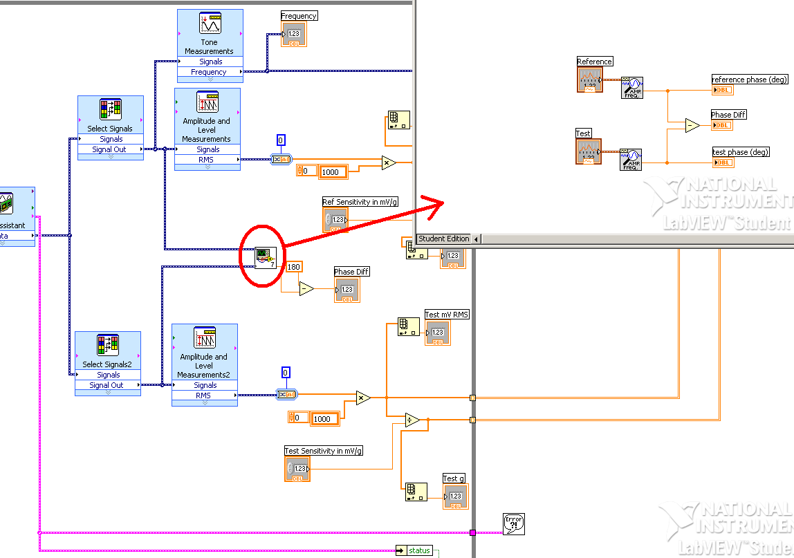
Here is the program that I use to measure the phase difference in an RC circuit. Simply generate a sine wave of 2 kHz in LabView and send it to the circuit using an analog output. Then I measure the exit sinusoid using an analog output. I also measure using n oscilliscope. I can clearly measure the difference in phase with the oscilliscope and know that it is about 1.4 radians.
Problems with the program:
Phase difference different measured each time the program is run for the circuit. It is never as good.Possible causes:
You will notice by looking at the vi that I measure the phase from the signal generator. Can I use a second analog input to measure the sine wave, as it came out at the beginning of the circuit?
I think it's a timing issue. While the phase difference is constant each time the program varies each track. So the time that each measurement of tone starts its first measure seems to be different every time and causes this reading of different phase.
The card that I use is a PCI-6221, is there a timing problem associated with switch for input and output audio acquistion or are they separated.
Is anyway to ensure that two key measures measure phase at the same point in the (real) time?
I would really advice or changes to the program - could someone offer me (I am a student and LabVIEW is not on our program so I have no support, but I use it for my project (OH!))
I would certainly acquire two signals. Food for the analog output right back into an analog input, then your signals filtered in another.
Initially, I would feed the two analog inputs of the analog output and measure the delay in phase due to the multiplexed A/D on map. Once you have this measure, you can feed in the filtered signal and then measure the difference of phase of this signal.
Maybe you are looking for
-
Automatic response to stop customers message
Hello. I am owner of a salon and I have a cell phone to plan my clients. I am very esaished and very busy and be a receptionist full time became a job full time. People are texting all hours of the day then with clients and the nights and weekends. I
-
Satellite S300CDS - upgrade RAM
Is it possible to increase the RAM in this model - and how is it easy to complete?
-
can not find the driver hdaudbus.sys
I want to install a new video card in my desktop computer and I can't find a driver. The card is a geforce 210 512 MB w/hdmi out. It is seeking hdaudbus.sys. What I read there is a problem with this driver and SP3. I checked the nvidia and msi si
-
How to check the files of Microsoft to be legitimate?
I have a Compaq Presario desktop computer comes with XP Media Center 2005. It has been updated to SP3. Recently, I ran free TDSSKiller from Kaspersky Lab to check my PC for the DNSChanger Malware. After executing TDSSKiller, he registered 6 files t
-
I recently turned on my laptop and my profile/account has not been recognized.
I recently turned on my laptop and my profile/account was not recognized during the startup of the computer toward the top, so a temporary account/profile is used instead. I did some work saved information on the computer using this temp-account pro