myRIO
Hello
I saw in the specification myRIO manual that it comes with a power cord, but it also comes with an adapter to plug into the wall? Or I have to buy it separately?
Additioanlly, if I turn off the myRIo servo-motors using myRIO to feed servos while the myRIO is connected to a laptop via the USB cable as well as the wall will be the servo motors draw power from the computer or they will draw power from the wall adaptor?
Thank you kindly,
James
Hi James,
1. Yes, both are included.
2. the servo should draw power from the wall.
Make sure that you are in business in the power output of the myRIO specifications when you feed your servo motor.
Tags: NI Hardware
Similar Questions
-
Engine for MyRio adapter command 2 DC motors
Hello
I have a question about the adapter engine for the MyRio. I found the following code example:
https://decibel.NI.com/content/docs/doc-45592
This afternoon, I was able to drive a motor continuous using this VI, but I want to use to control 2 Motors continuous. I tried the following (see photo) and it did not work.
What should I do for the second DC motor?
Thank you!
Hello
Well, the next time you post, it would be useful to have all the information to start with (what does your system, errors, measures
you have taken to solve the problem, etc.). This way more people will respond and we can help you more easily.
By parallel loops, I just run two processes in separate loops at the same time in the same VI (what they do on the link).
If you think about it logically if this initial process is running one engine, then do the same exact process but that it points to the
second motor will run the second engine. So, if you include the two pieces of code (exactly the same but different engines references) in the same VI then it can run two engines.
If you look at the link I have attached before she speaks of two ongoing processes at the same time within the same VI.
You can then use queues and the authors of the notifications (look in them) to communicate between the two processes you use, allows from Control Panel even before to control them and stop them both at the same time.
With this, you should be able to all both enforce.
Hope this helps
-
Reading of Thermocouple Type K with myRIO
I have a myRIO (room only) and I need to read for an internal PID K type thermocouple measures. I am able to do this directly in the room? Or I need an adapter?
Be as specific as possible.
Thank you.
The above listed connector is the connector for the card myRIO only.
In addition, the thermocouple type k has a + and - sign. If the + needs to go to one of the analog inputs and - needs to go ALWAYS, analog ground. See page 5 of the below myRIO 1950 manual for the pinout of the connector.
-
Palette controls MyRIO appears not
Hello
I recently received a myRIO. After graduating (relatively) comfortable with LabVIEW, I have connected the RIO for the first time and went through the getting started wizard and draw the graph of the accelerometer. However, when I tried to move forward to control the LED on the myRIO through a VI, I couldn't find the relevant icons to insert in the tool Palette, as shown in the tutorial. When I opened the tool palette there is no section "myRIO". There are some elements of the FPGA and the visionRIO controls, but none of the standard (I guess) LED control etc.
After some reading, I thought it's probably a problem with the Toolbox myRIO, I had installed LabVIEW and thought I installed the toolkit from the CD provided with the item. Idecided to erase and reinstall the Toolbox. With the CD, I uninstalled all myRIO toolkit that I had previously installed and rebooted, then installed the resources on the same CD and rebooted.
No joy, the License Manager NOR has not shown and myRIO toolkit under toolkits when I checked.
I am now installing the Toolbox to the web download of the group for the second time. After reviewing the previous posts on issues that seem to be the same as this, I have tried almost everything, and he seems not to have worked. When I open LabVIEW screen (where you can create the project/access those pre-existing) says "LabView... myRIO, ' is the LabVIEW installed from the disk of myRIO as far as I can tell. I don't see why it shouldn't.
Please help if you can. Let me know if the necessary information. I'm on Windows 10 on a HP Pavilion.
Thank you
Tom
Looks like you had open the VI was under the FPGA myRIOs in the project. Palettes will change according to the context of the VI in order to ensure that the VI is created under the myRIO. You can also view and modify the current context at the bottom left of the VI.
-
How to set an application built using the C API for myRIO 3.0 to run when starting on a myRIO-1900
It is even possible to define such an application to run at startup? If so how would you do it?
I've compiled a program using the API and eclipse distribution OR and can run Eclipse or by running while SSH in the myRIO. Is the only document I could find about this one: http://digital.ni.com/public.nsf/websearch/B37FA04A1CB84B6C862571A30060EF03?opendocument&Submitted&&...
The link is a little outdated, so I'm not sure of the relevance, it is today. I changed the lines of lvrt.conf to:
RTTarget.ApplicationPath=/c/ni-rt/startup/startup.rtexe
RTTarget.LaunchAppAtBoot = TrueNone of the settings seem to do anything. I also tried to run the program as a script using rc.local which does not seem to be used in the same way as it is in Ubuntu. My compiled pogram does not include the .rtexe extension although I can add it later that might not be the same.
I made sure that startup programs 'disable' has been disabled on the Server Web myRIO.
Thank you
Just in case someone has a similar question:
-
Hello friends,
I have a question. I need to trigger an output of Myrio with a single pulse. After the pulse, the output will remain active. Then with another single pulse, the output will be switched off. Should what tool I use?
Thanks for listening,
Kind regards
David
Hi Davi08,
I did a little research for you answer and I found another "NI Discussion forums" forum that maybe can help you.
Try using this link, I think this will help you.http://forums.NI.com/T5/academic-hardware-products-Elvis/myRIO-digital-trigger/TD-p/3278560
Best regards
-
Friends,
I need help with the following situation: I want to trigger a digital output of Myrio with just a single pulse, and after this impulse, the digital output must remain enabled.
Then with another single pulse, the output should be turned off
Anyone know how to make a similar request?
Thank you for the opportunity
Best regards
Q.Silva
Hi Silva05,
I did a little research for you answer and I found another "NI Discussion forums" forum that maybe can help you.
Try using this link, I think this will help you.http://forums.NI.com/T5/academic-hardware-products-Elvis/myRIO-digital-trigger/TD-p/3278560
Best regards
-
update firmware 3.0.0f0 in 1900 to 3.5.0f0 and propellant myrio works not when use turn the engine.
Dear Sir
I run this problem when I updated the firmware in myrio 1900 version 3.0 to 3.5. Before update, thrusters worked fine using the runtime engine, after update, propellers no longer exists. Any help will be much appreciated!
Thank you
Long
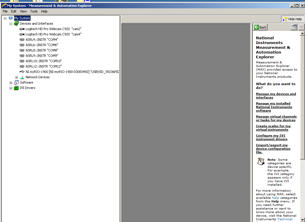
Hey Tao!
I'm glad to hear that your ports are now displayed in MAX. And I think it is a good idea to use the outputs analog on the myRIO. As long as you know the needs of the motor controller to order the right moves tension and a control loop in place, you should be good to go.
-
How to play a sound stored in myRIO
Hello
How could I call a file saved in the usr/local/sbin in myRIO and send it to play? Thank you...
I made this way. I turned the sound sample in a table (sound sample) and in another VI, I read this sample (creator of the ring). It works very well.
-
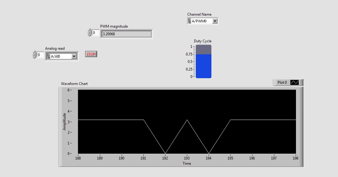
Problem in reading the PWM signals in myRIO 1900
Hi guys,.
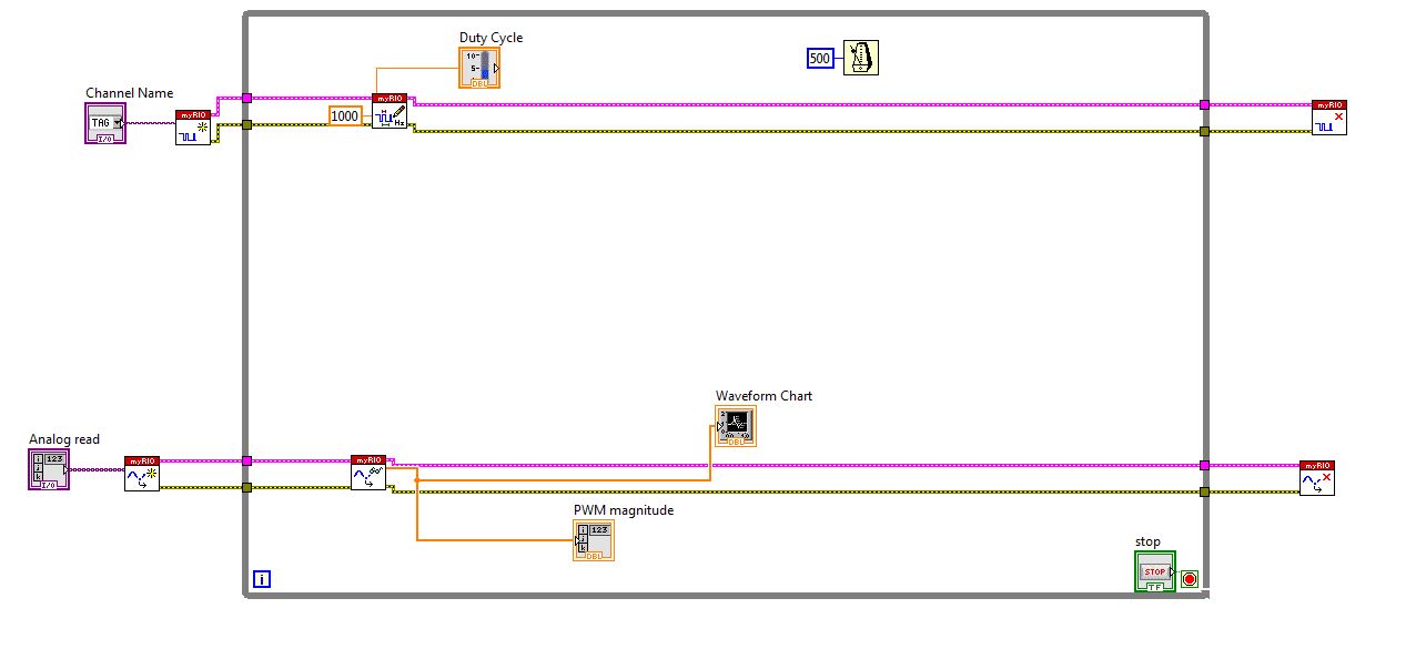
I work with myRIO to generate PWM pulses.
Here is the block diagram of my circuit.
I connected external to the analog input pin PWM pin. So I can watch the PWM pulse in the waveform table.
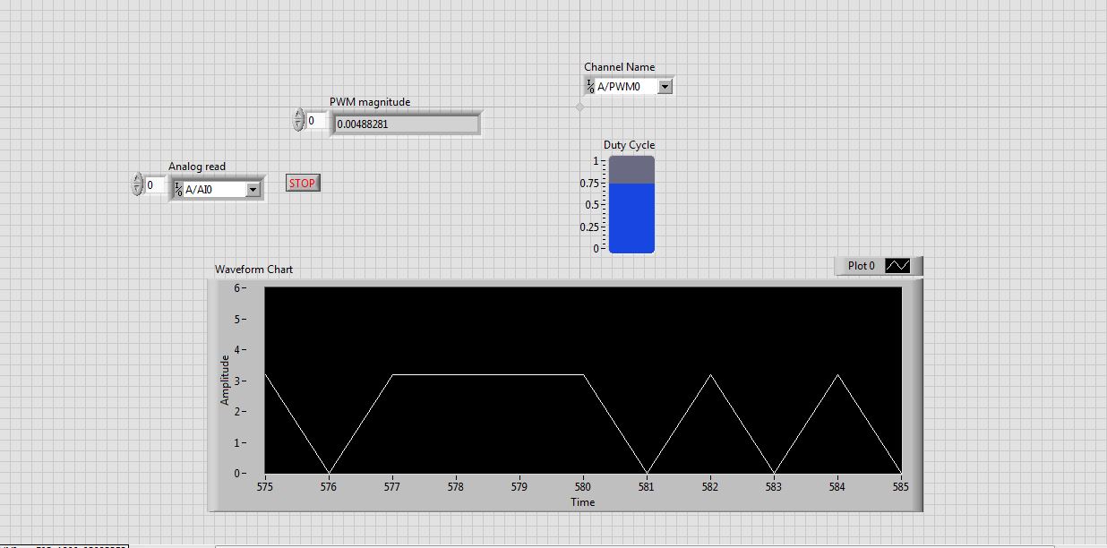
But the waveform is not clear. This is as shown in the screenshot.
See that the waveform is not correct. When I'm watching the same PWM pulses in the CRO (cathode ray Oscilloscope, oscilloscope real in the real world), I get exactly the waveform. that is, the PWM pulses are generated correctly. But the analog read is unable to read the PWM pulses.
I faced the same problem with the pin of analog reading earlier when I read the input voltage. Is not give continuous reading of the voltage input.
Please guide me how to read these impulses via analog read.
Please tell me at what frequency range, I can use this myRIO to generate impulses?
I am able to use 40 kHz?
Hi rcs.
The desired pulse frequency is 10 KHz. My sampling rate must therefore 100 kHz, which is not possible in data acquisition mode. There is another problem with the myRIO. Only AI0, BI0 and CI0 has n-sample mode. The analog input pins is still have no n-sample mode. But in my project, I need 4 pins of I in n-sample mode, which is not possible. In addition, the sampling rate should also be favourable, which does not happen in my case. We can say that this is a disadvantage of myRIO with data acquisition mode.
The only alternative to solve this problem is to use FPGA in myRIO.
He can taste a 25nS rate.
But little complexity is there -
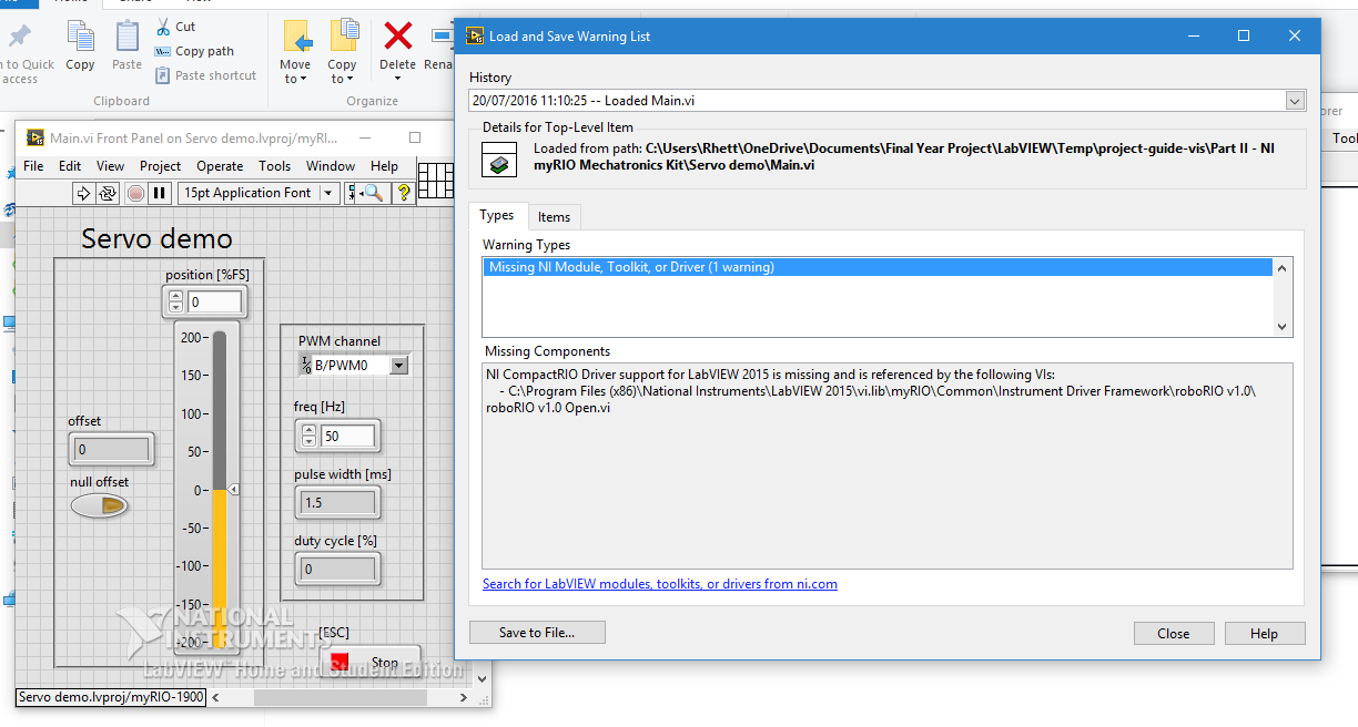
myRIO Servo demo does not: Servo sweeps back
Hi all
For the first time using LabVIEW and myRIO and I thought I'd run the demo of Servo. The question that it displays the following error message:
If I choose to ignore the error my servo works but don't stop at a point (hold the angle) and sweeps rather backward. This can be seen in the following video:
I'm honestly at a loss, I have virtually no experience with this hardware and software and the standard demo software does not work. I use an analog servo CS - 239 MG Corona.
Any help will be greatly appreciated

Hi Kathryn,
Thanks for all the help, you were extremely helpful
the solution was that I needed to power a battery pack as the myRIO provided far too little power. I found the solution in another forum of NOR and the OP knew exactly the same question. I have a battery pack on order and will update with the results.Kind regards
Rhett
-
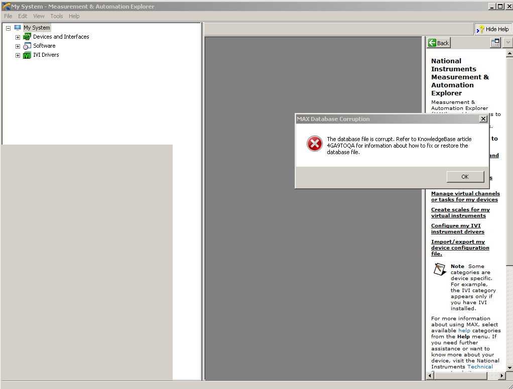
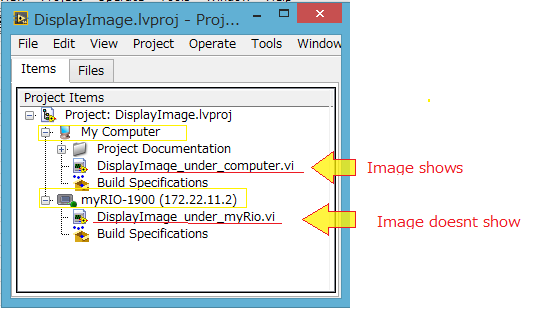
Display image on vi as myRio problem
Hello

This system supposed to be an easy task, but I don't know why it does not work. I am trying to create a game by myRio 1900 and I'm putting a jpeg image. However, I get an error message or an empty image on the Panel before the myRio Vi (Vi project myRio label) [see photograph below]. On the other hand, if I create the same VI under my computer, the image shows without any problem. What should I do to enlarge a picture on my VI as myRio. I need the image either on this VI because I am creating a program requiring myRio and it may not work properly if it is not under label myRio (I need its integrated sensor). I am attaching a zip file of only the part display image of the commandments and not my whole project easier to visualize.
Problem in brief:
Please see the project (as a zip). The vi computer label works and the vi under myRio does not.I want to solve:
I want to put an image on VI myRio label.I have:
MyRio Labview 2014
MyRio 1900
Already tried to: (but unfortunately did not work)
(1) put the jpeg file in the USB key and plug myRio directly. I gave the file path ' / u/bg.jpg ". (File system)
2) created by Subvi from 'computer' then it reminds on the (main) vi under myRio. And vice versa (Subvi myRio and MainVI on 'computer')
Please ask me any questions if you need further information. I will answer as soon as possible.
Thanks in advance for your help,

I am very greateful for your time.
Stephany
Stephany,
It seems that reading JPEG/PNG/BMP screws are not based on targets in real time, as your myRIO. As an alternative, you can get our Vision of shared resources (I think you need to install with Vision Development Module), install Vision RT to the myRIO and use the IMAQ ReadFile VI to open the file on the myRIO.
-
I'm new to myRIO and use it to measure sine wave (0V to 5V) of up to 10 Hz 20 KHz. I also quickly transformed of Fourier (FFT) of the signal measured in real time.
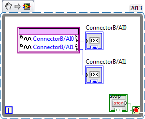
Sideways FPGA of things, I try to keep things pretty simple, just read 2 channels of AI (connector B: AI0 and AI1), therefore potentially able to read each HAVE 250 kech. / s (as the unit has a capacity of 500kS/s). Does that mean this program gets a two analog inputs data exactly every 4 microsecond? If this is not the case, how can I make sure that the data is acquired through a fixed sampling rate?
I realized that we can add to the FFT in FPGA function, but I wanted to manipulte the acquired data of analog inputs before it is sent to the FFT, which I don't know how to do now. Can someone explain me how do the arithmetic data (muliplication, division and so) on the acquired data and analog inputs to reducde the 12-bit resolution 10-bit to program FPGAS.
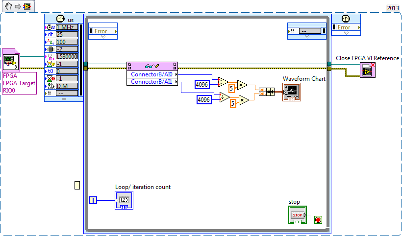
Later, I created a myRIO program to read analog data 2 FPGA program which continues to turn in timed loop. In the program myRIO, the timed loop is configured to 1 MHz clock source type by a delay of 25 microseconds.
This configuration means that the loop runs exactly every 25 microsecond?
When I set up the less than 10 micro second time, myRIO has stopped working. Why is it so?
Is it because myRIO cannot run as fast as FPGA?
It is advisable to make the FFT of myRIO side analog data or FPGA?
When I tried to do FFT using the power spectrum of myRIO side, he asked for waveform data. What I acquire is data analog. How can I convert in waveform data?
If I read in the forum for help, I couldn't have the full answer to my doubts
Discussions at the Forum I did reference:
A lot of good questions here, I will try to answer as much as I can so as to offer a bit of advice.
First of all, if you are looking to acquire data at a very specific rate on the FPGA, you'll want to use the Timer VI. You are also going to use a FIFO of DMA to transfer data of FPGA in real time. A node read-write using as you do now means you'll run out of samples, or read the sample even several times. The link below is a very good tutorial on how to do what I described above.
http://www.NI.com/Tutorial/4534/en/
Later, I created a myRIO program to read analog data 2 FPGA program which continues to turn in timed loop. In the program myRIO, the timed loop is configured to 1 MHz clock source type by a delay of 25 microseconds.
This configuration means that the loop runs exactly every 25 microsecond?
When I set up the less than 10 micro second time, myRIO has stopped working. Why is it so?
Is it because myRIO cannot run as fast as FPGA?
In general, you should not run a timed loop much faster than 1 kHz. Using timed inside loop knots, you can monitor the real rate of loop during execution to see if f you meet your needs of the moment.
The portion of your myRIO RT is slower than an FPGA in the sense where it cannot manage the rates of lines 40 MHz (he makes up for it by being able to work with much better pictures) and it is important to remember that it is just a computer. The advantage of a real-time operating system, is that you have more control on the Scheduler, not that he is faster (less jitter, not faster code). There is more good reading below.
http://www.NI.com/white-paper/3938/en/
It is advisable to make the FFT of myRIO side analog data or FPGA?
When I tried to do FFT using the power spectrum of myRIO side, he asked for waveform data. What I acquire is data analog. How can I convert in waveform data?
I would say that it is generally advisable to treat your FFT on the side FPGA as long as you have the resources available, but for many applications probably little matter ultimately.
-
Define a VI to run when starting on the myRIO when programmed in scan mode
Salvation of the forums,
Hoping you can help me with this please. Of course there must be a simple way for me to do, but can't seem to find anything through research on the main site of NOR...
I work with the platform myRIO and simply want a VI to run as soon as the myRIO is powered (no instruction of the user interface). I found the instructions on How to do it if the myRIO has been programmed using the FPGA and the host RT configuration but unfortunately the right click options are not available because my project/myRIO are set up using the analytical engine style mode (giving access to the range of myRIO etc.).
Ideally I'd rather avoid having to recode the system using a low level of coding, including FPGA due the heavy compilation for each iteration of the code using real data (with simulated test on PC e/s would be faster, I know, but it is unlikely to show me bugs in my code for what I need).
So in simple, could someone please point me in the right direction for setting a VI to run at start up/boot for the myRIO when it is configured and programmed using the scan engine?
Thank you very much!
It turns out, after all this (several hours trying to find missing options and research methods of how do!)
 this is because the Application Builder had been installed and as such has been activated, but NI License Manager was always waiting to finalize activation (activation running Assistant required).
Seems to work now but at least! No doubt lost a lot of time with her, but it's a learning curve!
So for someone who is struggling to find options to create a .rtexe file, make sure that your Builder Application is enabled!
-
myRIO ADC problem: side affacted channel of its previous channel
Hello
I use several channels ADC myRIO now and facing a question about it.
I use 3-channel ADC Port A: AI0 AI1 and AI2.
I have connected AI0 in the middle of a potentiometer for voltage accoss it. And connect anything to AI1 and AI2.
CDA works very well. I can move the potentiometer valtage perfectly AI0.
However, when I changed the value of the potentiometer, the CDA of AI1 and AI2 results changed also, 0, 1V to 0.8V about. Please note I have nothing plugged in these two ports.
Is this true? the ADC AI1 and AI2 and AI3 same (PORT A) port are affacted by AI0?
When I connected AI1 to an Anolog output senser, the result was also affacted by the potentiometer which was connected to the AI0.
When I connect AI1 in power, he was out of influence.
Did someone already had such a problem? Can someone help me to solve it?
Thank you
Fisher lah
It is the response of support OR:
Please note the small change you notice when both of your strings are attached can be due to several factors such as the wrong wire shielding, etc and EMC (electromagnetic coupling).
What is a floating channel terminal, random or variation is normal and due to internal correlated myRIO circuits and should not be a cause for concern.
Well, I'm still very confused.
Maybe you are looking for
-
input source indicator does not
Hello I have a problem with the input source indicator - when I change my language (shortened KB), it changes OK, but the light stays on English. Searched options in system preferences, but nothing helped. You can see in the attached screenshot: I we
-
There is a way to get the "add to bookmark and rss button" within the url bar?
I think that this two buttons must be in the url bar. Are easier to find and smaller than the bar.
-
Satellite U500-ez working slowly when I have powerd with battery
Evry time that I disconnect this computer from the power socket and tring to work with the battery-it strting to get hot and runs very slowly (on the use of the web!)Any suggestions? Thank youDan Post edited by: wiesd
-
Outlook Express inbox emails have disappeared
Inbox in outlook express has fallen six months of emails
-
Retrieve the Roaming user account
original title: roaming Recently, I was on a trip and when I booted my system using another connection he put me roaming and moved all my documents. He therefore established a new bureau. How do I get all my programs and documents and old office back