Rinse the target DMA to host FIFO FPGA
I have a program that runs on FPGA waiting for a ppr pulse 1 a coder, then begins to acquire data based on 4096 pulses of ppr. After that it becomes 4096 pulses, it synchronizes the back upward with the pulse of 1 ppr and recidivism. If the encoder stops spinning in the middle of a revolution, I have a timeout will happen, shouldn't get a pulse of 4096 in some time. This way my code isn't stuck wait pulses if the encoder stops turning. Then, it warns the user and synchronizes backup with the pulse of 1 ppr when spinning resumes.
Well, the encoder stops at Midway through a revolution of spinning, I get a timeout, but now there are 2048 (4096 ppr * 0.5 revolutions) stale data points in the FIFO. I want to get rid of these points so that once it syncs back upward with the pulse of 1 ppr, I have data in the FIFO, all of the current revolution. I guess I could take the timeout error and trigger a loop on the side of RT that removes the elements until the FIFO is empty, but if it is not in time, before the encoder starts to turn once again, I still stuck with stale data. Maybe I need some sort of handshake with controls? I could also put FIFO for target on the FPGA for storing data and not the tail it to go to the host until it is all there. If I get a timeout, I could please rinse on the FPGA FIFO, because there is a method for flushing to target FIFOs.
No matter which deals with this problem before, and how to solve?
Hello
I think that your first method is the best option. When you save a timeout, have triggered a case on your side of RT first making a FIFO reading which returns the number of items in the FIFO (but reads the items suck) and then immediately do a read FIFO that reads the number of items remaining. This will clear your FIFO and it should run quickly.
Tags: NI Software
Similar Questions
-
DMA between host and target FPGA is not supported for this remote system.
I try to cover with my FPGA (on the cRIO-9002) of the RTO. I have install upward of anOpen good VI reference without error, but as soon I try to access thefifo I error-63001 and the attached message wrote:
Error-63001 occurredat reference FPGA VI opened in the target - multi rate - variables - fileIO_old.vi
Possible reasons:
NOR-RIO FPGACommunications framework: (Hex 0xFFFF09E7) DMA from the host to the FPGA targetis not supported for this remote system. Another method for controller of e/s or climatiqueLes associated with the FPGA target.
What other I/O optionsdo I need to move the data asynchronously to the RTO for the FPGA. I have triedcreating memory, but it seems that I can't write to the memory of the RTOSside.
We have also a 9012sitting around will using this cRIO rather solve this problem.
I'm very very greenwhen it comes to LabView, so I apologize if this is an easy question.
As stated in the readme of the driver NOR-RIO, DMA is not taken in charge from the host to the FPGA on the cRIO-900 x series. The cRIO-901 x supports DMA transfers between host and FPGA and FPGA to host all the cRIO-900 x series controllers only support transfers the FPGA host DMA. As a result, LabVIEW returns an error if you try to transfer using DMA controller for cRIO-900 x.
The 9012 looks like the ideal solution, you are very lucky to have additional hardware laying around

-
Host DMA to the synchronization of the target
I use two hosts to target DMAs to generate two arbitrary waveforms to be taken out of the anAO module. I want these waveforms at the exit at the same time, but it seems as if the waveform leads the other by several micorseconds. The two waveforms are in two separate tables, passed to the DMA. It seems as if the shift is on the side of the host. I tried using the timing with the vi sync loop and the offset setting timed loops, but that seems to increase the interim more, or no effect. Is there a way to get these DMAs to start to pass the data at the same time?
Peter
What you can do is pack the two waveforms in a DMA and analysis, and then to the AO.
AO generally uses I16s to represent the waveform data and the bus DMA U32.
Use the number of join to combine both forms of wave, then DMA composite signal, then use AO divide numbers.
I used this successfully with good results.
-
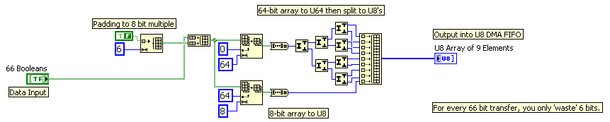
How can I transfer more 64-bit data to the target host?
Hi all, I currently use fpga PCIe-7851r card to drive my camera. There were 64 lines to remotely control. So what I did generates the commands on the host pc and transfer it to the target via DMA FIFO. The data type of the FIFO is U64, i.e. each digit control 64 DIO lines. But the issue becomes complex when I transfer 66 command-line. I tried to create 2 FIFOs, but I can hardly do the 2 Sync FIFO.
I think I might be able to create 2 tables U64, one contains the original 64 line, s command and the other for the 2 line (a loss) information. And then I have them interleave in hospitality and decimate them in the target. There should be enough cycles to it. But I don't think it's a good solution. Is there a better method? Thank you.
LabVIEW 2009, Windows XP, PCIe-7851R
Kind regards
Bo
Using the techniques highlighted in this tutorial:
http://zone.NI.com/DevZone/CDA/tut/p/ID/4534
You can use code like this:
-
Hi all:
I was working normally with my NI9024 CRIO to my work. I went home and when I came back the other day. I tried to compile my application to work.
The surprise was that I got a strange message "access denied: the IP address of this computer host is not on the list of eligible access of the target." Now, I can not connect a CRIO device. I tried to reset all the IP addresses in the CRIO and my PC computer. What can I do?.
Yes. This is the solution. I had to uninstall the NOR-RIO software on the target. I have uninstall everything on the CRIO. Then I reinstall the software, but I had also to program the fpga, the host and target. And I also have my IP, on the measure and automatition software. I found a big bug I guess.
Thanks anyway. National Instrument of love. Hope to work there one day.
-
In the target FPGA read/write control function?
Hi people,
I learn a lot from the sample project FPGA, including how you can easily retrieve and set controls and indicators in an FPGA using the read/write control function running in an RT target.
However, I can't find a way to do something similar in a FPGA target. I've been down this road before - that is, trying to move the data in/out a looping VI FPGA (void) to a (parent) FPGA VI - where my memory points to reach what I needed use.
So I was happy to see the palette FPGA enabled me to drop the control functions to read/write on a FPGA vi target. But alas there where tons of errors (not compatible son for target, etc.) and I guess now it's not possible.
So, just to be sure, I'm not missing something, is there something like control functions to read/write to use in an FPGA for read/write in an another FPGA (looped)?
In addition, why would I be able to read/write on a FPGA vi control functions if they are not supported? (Sorry for the n00b question)
Thank you
Steve
maherhome wrote:
You're right that I don't have this knot in my palette. However, I also do not seem to have a Refnum Occurrence in the palette is in the FPGA (see below), but I need to synchronize several loops of FPGA and added research using the textfield in the VI editor (and if compiles and runs). So 6 months to Labview and I'm fuzzy on how the palette is restricted
I don't know what you're trying to prove here. There is no control of refnum in search in your image. Occurrences are available in FPGA, and for control of refnum for one you just right click on a function of the instance and create a control. If you can create a valid thread of a certain type of data, then you can create a control or the indicator for it, regardless of the question to know if this type of control or indicator appears in the palettes. However, the functions that you can use in the block diagram are limited by what is available in the palettes.
maherhome wrote:
Regarding orders read/write for the FPGA/lights, I'm surprised that the infrastructure developed to allow read/write between RT and FPGA has not mobilized to allow read/write between FPGA and FPGA. The elements of memory function, but they are less convenient.
You may have noticed that you cannot compile the individual parts of an FPGA VI and combine them later; This is because when you compile an FPGA VI, all its subVIs are essentially merged to create a single block diagram (with additional logic if one not reentrant Subvi is used in multiple locations, this is why it is not recommended on FPGA). The subVIs no longer exist in the FPGA compiled; reading and writing a control on them would make no sense. If you want similar behavior, use global variables - but understand that global variables store values in FPGA logic resources. Using the elements of memory (or FIFO, which can also store in memory) leaves more fabric available FPGA logic by storing data in resources specially designed for this purpose.
-
Hello folk of LabVIEW FPGA,
I have a project on target FPGA X, and I ran out of resources.
I want to recompile it on Y to the target to see if I'll be better off.
I saw this article
http://www.NI.com/white-paper/5075/en/
What explains the steps required at the port of the target of the target.
But in my case, I have multiple FIFO and registers said... I really wouldn't go well the process of re - declare them again, not manually, this could be source of errors.
Please see screenshot for clarification on what I mean.
So, is there advice, what a FPGA gurus you can give me to help out me?
Is there a way that I could copy a section of the LV Proj XML or somethig so that I don't have to report again to the hand like a robot?
Thank you
Maciej
so Bravo goes to a colleague of mine.
What you can do is select all the elements (of the FIFO and registers) you want to copy.
Go to the menu of LV Edit-> copy.
and then go to the LV menu in the new project, select the place you want to stick to the and then edit-> paste.

-
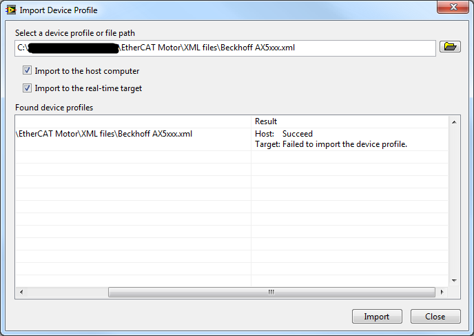
Part 3 EtherCAT Slave: importing XML Device Profile succeeds on host but fails on the target
Hello
I'm trying to control a 3rd party via EtherCAT servo drive:
- Master: NOR-cRIO 9024
- Slave: Beckhoff AX5203
I downloaded the files of unit on official website of Beckhoff Description: http://www.beckhoff.com.au/english.asp?download/elconfg.htm (Beckhoff_EtherCAT_XML.zip)
I followed the instructions to http://digital.ni.com/public.nsf/allkb/FDA1318A8909D02C862574510060DB62 to import the profile description of the device.
Curiously, the import was successful for the host (and I can now access this device in the LabVIEW LVPROJ file), but it failed for the target.
Why could this be? (There are no diagnostic messages)
Hi JKSH,
Looks like you are using NOR-Industrial Communications for EtherCAT 2.7 or later. What is you project connected to the target when you try to import the file? How are you connected to the target? What is your firewall block FTP transfers? Do you need the ability to programmatically discover slaves EtherCAT (such as DSM or using the VI of Modules Refresh)? If you just want to program the EtherCAT Slave in the LabVIEW project, import the device description files to the host is all that is needed.
Best regards
-
I'm trying to transfer a picture of the LabVIEW host program to the target in real time on a cRIO.
I'll set up a controlled loop that transfer values one via shared Variables.
It works fine when I run running to highlight.
However, if I have both allow to run at full speed, something goes wrong
and the size of the array ends correctly on the target.
Is there some tricks on how to transfer tables down
host to the target, or all the other pitfalls I should be aware when
work on a real-time target?
And Yes, I never took the course of the RT, so there might be some vital info miss me.
Martin
Hi Martin,
Why don't you use a SharedVariable taking a picture? Why can you transfer data one by one?
-
How to use the target FPGA and co. on the same chassis cRIO?
I have a cRIO system consisting of a master chassis 9074 with several modules IO and EtherCAT 9144 slave unit.
I want to run a CIE (see: http://zone.ni.com/devzone/cda/epd/p/id/5333) on the chassis of the master, this uses the analytical engine. At the same time I have to do some very urgent measures if I want to use the Board in hybrid mode, using analysis and FPGA engine at the same time (as described here: http://digital.ni.com/public.nsf/allkb/0DB7FEF37C26AF85862575C400531690.)
But as soon as I add the FPGA target at one of the chassis, the feature of the ice on this chassis stops working. After some research, I found that the CIE can initialize is no longer the modules belonging to the frame that has the target FPGA on it. Error in the method Init of the CIE is: 65700 (indeterminate). This occurs when you try to use "for a more specific class' on the modules configured with a target FPGA on it.
Someone knows what can cause exactly this problem and perhaps provide a solution/work around?
Many thanks in advance.
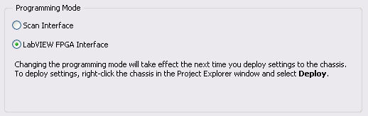
Hybrid mode requires you to have a bitfile compiled running on the FPGA to be able to read the Scan Interface IO Variables. Move the target FPGA at the RT target module will allow Interface of scanning for this module, but the frame will always mode Interface of LabVIEW FPGA.
To get fair access to the scan mode for the frame, right click on the chassis in the project, and choose Properties. Then, modify the Scan Interface programming. If you want to continue using the programming of FPGA and the Scan Interface set (hybrid mode), you will need to compile a bitfile (empty if you do not want programs on the FPGA again or containing your FPGA code). By compiling, the support of the module scan mode for the modules under your RT chassis is compiled in your custom bitfile. Then, on your VI RT, you need to use reference FPGA VI open to your newly compiled VI. Once this VI is deployed and ongoing implementation, you get the data from you are the CIE.
For more information, see this knowledge base article and Reference Interface of Scan CompactRIO and procedures.
-
SIT error 14104, dll runs on the host, but not on the target
Hello
I have problems of deployment dll (compiled in 2007 with Microsoft Visual C++ .NET 2003) Simulink in LabVIEW (2009 SP1). My target system is a desktop PC with LabVIEW Real-time 9.0 installed.
I created a simple Simulink model which mulitplies an entry with a Gain and returns the result. I compiled using the nidll.tlc as a target file system.
Then, I created a LabVIEW RT application that uses this DLL. I created exactly the same application as the host VI and VI target. On the host VI everything works fine. On the target VI, I get error SIT 14104.
What I did to solve this problem? I followed the steps on http://digital.ni.com/public.nsf/allkb/C7FF960E0A6C219A8625729600104615 . I have manually deployed the dll on the target computer. I used the suggested compiler. There is a lot of memory on the computer (RAM and HDD) target. And I'm not using a CRio system.
Does anyone have an idea how to fix this error? I will attach the sample project labview and the MDL and DLL to this post. Don't forget to adapt the DLL-path if you test the program.
Kind regards
Thomas
Well I found a solution.
I had to deploy the DLL manually on the target, but not in
ftp://IP_Address/ni-rt/system/as the link above is said but rather inftp://IP_Address/.Problem solved.
Kind regards
Thomas
-
I moved a listener on a host in a House different oracle. The headset works fine, but EM 12 c shows that the listener is down with the following summary:The listener is down: even if a listener with the name "AUDITOR", is running on this host at the port: "1521", it has not started using "the target LISTENER. ORA file. CORRECTIVE ACTION: To monitor this "EM listener target" with its current configuration, you must stop the process of listening running and start it using the Listener parameter file: opt/oracle/product/12.1.0.2/network/admin/listener.ora. Alternatively, you can update "this target LISTENER. Location ORA setting"with the location of the listener running, which started using the: opt/oracle/product/11.2.0.3/network/admin/listener.ora.
EM 11 g, I simply changed the configuration of the listener for the different oracle home, argued the change and in a few minutes the listener would show that 'UP' with the oracle of new home. I upgraded to MS 12 c (12.1.0.4) and can't find how to do this. Can someone give me the procedure.
Thank you
Ron
Hi Ron,
Can you please do the following?
-Create a for the listener listener.ora file, stop and start the receiver using the listener.ora file. If the file is located in a default location, set the TNS_ADMIN environment variable to that location before you start the listener.
-Log on to the EM console, go to the homepage of the listener.
-In the Oracle Listener menu, select target Configuration > Configuration of the analysis.
-Ensure that the parameters, including the Listener.ora directory, are properly.
Kind regards
-Loc
-
How to debug the program Labview that runs in the target of the RT of a Compact RIO
I use CRIO-9073 for the acquisition of data from sensors. Program Labview is written in RT target and target FPGA. It is posssible to make step wise execution for the program written in the target RT and FPGA target the way purpose us for the debugging of the program in general OS.
MJM,
The only way to use the debugging on a VI wrote to FPGA tools is to simulate running on the host computer. You can then deploy the compiled FPGA code on the target and run your VI RT in debug mode if you use the communication of the façade with the host PC.
-
Cannot run Simulink DLLs at the same time that the execution of the target time real VI
Hello
What I try to do is run a dll created in the Simulink model to control some servo through a CompactRio 9014.
For the moment, I managed to create three screws
(1) in the FPGA target that performs the PWM channel desired
(2) which takes the value of a variable that contains the desired position and network that feeds to the 1st VI
(3) a VI that is running on the host computer that changes the value of the network variable to change the position
I can get these three work screw and the servo controlled, but when I try to update the value of the network variable using simulation, by deploying to the target of RT simulation and running, he said:
' Access denied: this objective is already used by another host or project. »
I guess that's because the project is already connected the cRio, so I unplug and am able to deploy the model files.
However, when I try to run one of the screws in the Targer RT as well as simulation I get the error:
"This VI is downloaded to the target, but is not present in the project you are trying to deploy. All the screws on the target will be closed unless you choose to add the missing project VI. »
With a large number of missing screws...
I'd do this wrong, i.e. is there a simpler way to control inputs FPGA using the simulation, or is there something I have missed?
Thank you
Geoff
Hi Geoff,
I think I understand what you're trying to do and what you've done so far.
If I'm not mistaken you have passed through the SIT connection manager, set your target RT (select DLL, mappings and hardware i/o) and this is his 'magic '. If this is the case of look for the project pilot LabVIEW which was created by the SIT connection manager. This should live in the same folder where is your DLL. Open the pilot project, search for VI driver and open it. Then go into the Sub - VI # 5 has with the name of the loop rate Base. It's the Subvi who reads/writes on the material and the reads/writes the data to the DLL/OUT model. If you want to read the output of your model and then manipulate the data that is where you need to add your code.
Inside of this Base rate loop VI there is a Subvi with number 4 and called SIT take model Timestep. This VI is the one who makes the call to the DLL model. The output of this VI is your data from the model. This data goes into slot - VI # 5, which is responsible for the drafting of these data to the material. Since you want to manipulate that data from the model, you need to recover data from the wire coming from the Subvi 4 (SIT take model Timestep) before it gets to the Subvi # 5.
In this VI of Base rate loop, you will see that there are a few empty block structures. These images are for you to put any code you want. The reason is that any changes you make to the driver VI and subVIs that aren't inside of these frame structure will be lost if you decide to go in the connection manager to sit DOWN again and make some changes. The VI pilot gets new script whenever you do something in the SIT connection manager. Whatever it is inside these frames will not be erased.
So, if you have a code you want to run in parallel to the simulation you just have to drop it inside this driver VI. Very probably within this Subvi 5 (Base rate loop). To add your code just drop the VI in one of these settings and make any changes that him so that he can read the data in the model. Furthermore, the model (Subvi 5) data in a table. For the index of each element in the array and its meaning look for a file in the same folder where the DLL is named
readme.txt ports. This file has a description of the inports and small ports and their indexes. This VI driver is called when run you the host VI so you won't have to run sepearately.
Kind regards
Ricardo
National Instruments
Systems engineering
-
You try to run the scan mode and mode interface fpga at the same time is causing errors
I'm reading a 9236 9237 and a 9215 with the scanning engine and read from two 9211 modules with the fpga. It's because I need to acquire to 200 Hz with the 9236 9237 9215 but maximum rate of the scan engine is limited by the slower module in the system, which in this case is the max of 15 hz the 9211.
So to use both interfaces (scan engine and fpga), I followed the percisely given in this article for instructions.
1. the project has created and added the peripheral crio using the interface of the scan engine.
2. Add the target fpga and drag and drop the 9211 inside modules
3. has created the fpga in interface file with and compiled with no error.
4. interfaced with the file fpga at almost exactly the way the sample project of "getting started with 9211' by using the engine of analysis in the interface with the other modules.
5. after the errors to discover that I created a VI that tests for just the portion 9211 code (called "thermocouple FPGA method Test.vi")
The data returned by the interface fpga was nothing else than zeros on all channels, even if thermocouples were hooked on some of them. (all zeros as entries in the convert temperature vi gives-410, 6160 degrees F, if you happen to have the material to try this.)
I get the following error from the open fpga vi reference:
code error-61141
"Thermocouple method Test.vi FPGA.
Activities FPGA:Open FPGA interface reference.
Reserved outside LabVIEW FPGA: turns The RIO Scan Interface. You must set the mode Interface FPGA chassis in order to unlock the FPGA. »It's extremely frustrating, because as I explained, I've been very attentive not only follow the instructions for concurrent fpga and analysis but also to model my VI by the example of VI, even if only for the moment, just to try to work things out.
Any help would be appreciated as I need to fix this for the further development and I am somehow in a lack of time. I opened a support ticket (reference #7256226), but the app engineer had no time to answer.
My system:
cRIO-9014 controller RT with crio-9104 bottom of basket.
LabVIEW 2009
Latest drivers and peripheral software pc and rio (RIO scan 3.2 engine support june2009)
rex1030 wrote:
I'm reading a 9236 9237 and a 9215 with the scanning engine and read from two 9211 modules with the fpga. It's because I need to acquire to 200 Hz with the 9236 9237 9215 but maximum rate of the scan engine is limited by the slower module in the system, which in this case is the max of 15 hz the 9211.
This should not be the case. 9211 data will not update with each sweep, but you should be able to run the scan faster than 15 Hz without problem. Do you have specific issues with this?
So to use both interfaces (scan engine and fpga), I followed the percisely given in this article for instructions.
1. the project has created and added the peripheral crio using the interface of the scan engine.
2. Add the target fpga and drag and drop the 9211 inside modules
3. has created the fpga in interface file with and compiled with no error.
4. interfaced with the file fpga at almost exactly the way the sample project of "getting started with 9211' by using the engine of analysis in the interface with the other modules.
5. after the errors to discover that I created a VI that tests for just the portion 9211 code (called "thermocouple FPGA method Test.vi")
You can try making sure that the chassis is set to mode Interface FPGA and the setting is deployed. I wrote that article that you referenced says will select the deploy option later and not explicitly speak to deploy the chassis later. Run a VI with a reference open FPGA vi not automatically deploy chassis settings if you need to do it explicitly. Try the following steps.
1. right click on the frame element and select Properties. Make sure that the Interface FPGA option button is selected. \
2. right click on the frame element and select deploy.
3. repeat your VI.
The data returned by the interface fpga was nothing else than zeros on all channels, even if thermocouples were hooked on some of them. (all zeros as entries in the convert temperature vi gives-410, 6160 degrees F, if you happen to have the material to try this.)
I get the following error from the open fpga vi reference:
code error-61141
"Thermocouple method Test.vi FPGA.
Activities FPGA:Open FPGA interface reference.
Reserved for LabVIEW FPGA outside: The RIO Scan Interface is running. You must set the mode Interface FPGA chassis in order to unlock the FPGA. »The likely cause of this error is that the setting of the FPGA Interface on the chassis has not been deployed. If the chassis is still Mode Scan fixed personality bitfile will be loaded on startup and the FPGA will be locked.
It's extremely frustrating, because as I explained, I've been very attentive not only follow the instructions for concurrent fpga and analysis but also to model my VI by the example of VI, even if only for the moment, just to try to work things out.
I'm sorry that you have had difficulties. Assuming that I'm wrong about the source of your problem, it seems we have to update less than Ko to include the deployment step.
Any help would be appreciated as I need to fix this for the further development and I am somehow in a lack of time. I opened a support ticket (reference #7256226), but the app engineer had no time to answer.
My system:
cRIO-9014 controller RT with crio-9104 bottom of basket.
LabVIEW 2009
Latest drivers and peripheral software pc and rio (RIO scan 3.2 engine support june2009)
Maybe you are looking for
-
Why Aspire Firefox for Android?
Firefox on Android 2.3.7 is probably the worst software I used it all. Short boot, it is an unusable product. 1 horizontal orientation distorts the graphics in an unusable state.2. access to text fields pop-up keyboard input, but distorts the graphic
-
I have a software that is not compatible with FF4. I would like to revert to a previous version of FF. Perhaps 3.x. Is it possible and how can I do this if it is. It will probably be a short-term situation until the software is updated for compatibil
-
Laptop HP 15: updated processor
Hello! This is my first post here so excuse any errors please! So, I have a Hp i3 3110 M, bridge of Ivy 35 W, socket 988b rPGA, 21ga 39.5 motherboard and I would like to upgrade to i5. Could you recommend / tell me if there are all compatible process
-
Got my new SL1 yesterday, unpacked all, put the battery on the charger and loaded the software on my computer. The battery was ready for use, but when I tried to put it in, it won't stay in or 'click' into place so to speak. Anyone have any suggesti
-
Trying to connect using a 4 G Verizon Wireless USB Modem
I'm tying to get an internet connection through my company of Verizon Wireless, with a 4 G USB Modem. The latest information I got from them were to download a newer version of the VZ Access Manager from the internet. When I did all downloaded corr