Number of FPGA FIFO DMA channels
Hey there,
to understand some of the problems in my FPGA VI, I wanted to know, as I need to see the count of 3 FIFO of DMA channels available:
(1) the total number of DMA FIFO created in the LabVIEW project
(2) the number of DMA-FIFO-method-nodes of the used in the FPGA VI
In the case of #1, is there a limit using the FIFO-node, or placing them in cases very intertwined Structures?
I've known a few problems in my FPGA VI, while using only two DMA-FIFO and access with the 3-node method on the FPGA VI hole I got the following error message:
There are insufficient DMA channels available on the current target. Too many DMA channels have been requested or some channel requests are conflicting. The current target has 3 DMA channels. Review the list of requested channels and remove one or more to free up resources.
So, I looked everywhere, but I have not found the target list of channels requested.
I had only created 2 DMA FIFO in the project, I used only 3 DMA-FIFO-method-nodes in total, and I used only a buffer size of 511 items in each FIFO.
So where can I find the list of channels requested, to see what goes wrong in this VI?
Thank you very much!
In my view, that the limit is the number of DMA channels, referenced in the VI. You can create as many as you want in the project, you just can't use more than three in a FPGA design. You use the scan mode? Who will also use the DMA channels.
Tags: NI Software
Similar Questions
-
Transmission of data to the host of RT to the FPGA via DMA FIFO
Hello
I try to write data from a host of RT on target FPGA using DMA FIFO and then process these data and read then return of the FPGA target to the host of the CR through an another DMA FIFO. I'm working on the NI SMU chassis 1062 q, with the built-in NI SMU-8130 RT controller and target FPGA NI SMU-7965R.
The problem I face is that I want to send three different tables, two of the same size and the third with different size, and I need one more small to be sent first to the FPGA. I tried to use encode dish with two executives in the FPGA VI. In the first image, I read and write the first table in a while loop which is finite (that is, a finite number of iterations). The second frame contains the process of reading and writing the second two tables (of the same size) in a while loop that can be finite or infinite (depending on a control). The problem is that it does not work. 2 arrays are displayed on the front panel of the RT VI host and works well, however, the table that should have been read in the first sequence does not appear on the front panel of the RT VI host. It is not sensible because if it is not passed from the host to the fpga and vice versa then the second image should not have been executed. Note that I'm wiring (-1) for the time-out period to block the while loop iterations until the passage of each item is completed. So the first while loop has only 3 iterations. Could someone help me undersdtand why this happens and how to fix this?
I enclose a picture of the host and the fpga vi.
Thank you.
If you vote for my idea here and it is implemented, you can even omit the loop FOR fully.

(I also propose the RE / IM divided inside the loop FOR and perform operations on complex table before the loop the transpose and reshape .) In this way, you only need one instance of these operations. You might even save some unnecessary allocations table in this way)
-
How data for chart FPGA of DMA Fifo and relaxation
Have a design Question here:
IM using a FIFO DMA here at the flow of data from the target to the host. Side host, I was using the FIFO read Functinon, converting to Dynamic Data and display in a chart in 'real time '. Pretty easy.
However, I would like to make it more functional. The incoming signal is essentially a square wave. I want to trigger on a rising edge, and then graphic permanently the result in the table. I tried to add that 'trigger and Gate' express Vi, but its uneven (see attached photo).
I am on the right track, or should it be done differently? I was not able to find specific examples for this. I think Im getting messed up because my data are read from the FIFO as a table 1 d, 5,000 items at a time. All of the other examples I've found just show the signals that are generated on the host computer already at a fixed frequency.
Thank you!!!
Bones349,
Hello! Some ideas/questions
1.), you could make a detection of edges in your FPGA, saving you a lot of treatment because no no need to spend no relevant data until the host code.
(2.) what you're doing in splitting the numbers before their conversion to the type of dynamic data? I'm not surw what happens there. You can use a data type of waveform instead, because she would have an element of time to your data.
3.) 5000 incidentally both through your FIFO would be fine.
-
Hi al, it's a long!
I noticed a strange behaviour when I read from a FIFO DMA between FPGA and RT host on my crio (9014 controller and 9104 bottom of basket). The FPGA is writing data to the FIFO 2 points every millisecond and the loop of the RT is the reading of 500 data points each loop of the MS 250 CR period is controlled using the hold until the next ms multiple function.
Wait until the next use means ms that during the first round, the wait will be not so I gave the FIFO DMA read method a timeout of 750ms to allow data points to accumulate on this first iteration.
I then ran the VI and it read the data as planned and it was always 0 in the FIFO. Then using the system monitor, I noticed the CPU usage on the RIO and was surprised to see that it was 30%
 !
!After a lot of puzzle and many other attempts as to set the timeout to zero if delays fair read until here, I've decided are enough data points and then executes a little behind so that there is always a constant number (non-zero) of data points in the FIFO. Now, the VI runs and only use about 3% CPU.
I thought that in the first case as I read exactly the number of points in the FIFO that I was tripping some kind of voting behavior in the playback feature which has been hogging the cpu.
So I ran a business with a zero time-out, where I was reading with 0 points of data to the left in the FIFO as in the first case and waited to see if the delay of read but it never does and the CPU usage is normal.
So what's happening? I'm puzzled!
Thank you
Steve.
Hi Steve,.
I think I can explain the use processor behavior that you are experiencing:
Case 1: Loop with nonzero time-out
-Your code starts with wait a multiple ms: This means that a 0-250 ms timeout occurs (on average 125 ms)
-Then your code tries to read 500 data points in the DMA FIFO (if 500 points come in every 250 ms). All data cannot be presented yet.
-If 500 points are not yet ready, polling occurs until they are. During the time of the poll, the CPU usage is high. Finally, the data is read.
-The next iteration of the loop begins.
-The code is now expected up to 250 ms after the last function call until the next ms Multiple. Roughly the same amount of data should be available by the end of this expectation as in the last iteration. Therefore, the question about the next FIFO DMA read should be roughly the same, and the CPU usage will remain high.
Case 2: Loop with zero time-out
-In your code, immediately after the first call to wait until the next multiple ms, you "synchronize" by reading all the remaining data from the FIFO.
-In the next iteration of the loop, we can expect the call until the next ms Multiple wait the entire 250 m means that the data DMA FIFO (discount jitter) should be ready. If jitter is low enough, this will result in delays very little of the read DMA FIFO and a low CPU usage.
I would recommend either using a timed loop and read the exact number of data points available (if your application can handle variable size data sets), or using a while loop as you are and make sure that the loop priorities are defined such that the CPU usage high does not affect critical functionality.
Thank you for the very good question; I personally really like thinking through these issues! Please let me know if you have any questions that deserve further discussion and have a nice day!
Kind regards
Casey Weltzin
Product Manager, LabVIEW Real-time
National Instruments
-
Hi all
I'm under LabView 2013 and have updated all drivers and versions on my local computer and also on the Single Board RIO 9636 I use. My goal is to measure 4 similar entries corresponding to four different microphones and then each individual signal as an output wave form. I try this using the FIFO DMA 4.
The problem that I am running is that I am not able to read data from the RT Microprocesssor VI using the FIFO 4. Reading methods. I'm relatively new to using a FPGA and labVIEW programming. I attach two diagrams for information purposes. I thank in advance for any help, you may be able to provide.
mcoe12 wrote:
What happens is that data from the FIFO are just 1 and the real are not the case of the incoming data.
AH! If you said that in the first place, I have identified the problem in the first post. It seems that your data types do not match - fixed point for the FIFO DMA configuration does not match data from the analog input. That's what the small red "points of coercion" you are showing on writing of FIFO. My guess is that's why data is not properly through.
While you edit digital representations, also change the sampling frequency is an integer, to match the input of the timer.
-
Accuracy of size for the FIFO DMA
I started to develop a code of RT for cRIO with DMA FIFO function application. A few questions have very fundemental
fluctuated around in my mind. The FIFO DMA is supposed to be made up of two components FPGA)
side & on the RT side).
1 the total THAT FIFO composed of FPGA side FIFO + RT side FIFO?
2. the FIFO of DMA size that I put inside the FPGA target in the Project Explorer refers to what just FPGA)
FIFO or Total size)? If it's just FPGA side FIFO, how big is the RT side FIFO together (is
It automatically assigned by RTOS free memory function)?
3. in addition, size defined programmatically by using DMA-configure is the equivalent of setting the size
in the Project Explorer?
4. Finally, how can I estimate the maximum size of the FIFO that I am allowed to use?
Thanks in advance for any response.
Hi Shiva419,
1. Yes, at least a DMA FIFO has these two sides
2. I just read in another reply that the size you set for the FIFO in the Project Explorer is the size of the FIFO on the side FPGA. The size of the FPGA on the side of the RT is much larger (default is 10000 items).
http://forums.NI.com/NI/board/message?board.ID=280&message.ID=5108&query.ID=99697#M5108
Mandar-
-
Not sure I understand the FPGA FIFO resources
Hi all
I'm having a problem with FPGA FIFOs. I'm performing a target-to-Host DMA transfer, and I have two different configurations that use the same FIFO, but have radically different resource allocation. In the first case below, FIFO is a loop which will be called 1 time k each time the loop runs. In this case, when you map the Slice LUTs used are about 15%
In the second case, below, the FIFO is called once when the while loop is executed. In this case, the use of estimated resources regarding the Slice LUTs is 107%. I guess I don't know why this behavior should be expected. Can someone explain this to me? Thanks, Matt
Yet once again, take a look at the link resource use statistics. You do most or all mathematics in 64-bit and use of resources grows with the increase of the bit widths. In particular, logical shift, you use a lot, is a particularly costly and to a 64-bit value requires choice tables more than two times more than the same operation on a 32-bit value. I suspect that the implementation is really a huge table - for every possible way of entry that there is a corresponding output. This allows him to be very fast at the expense of the FPGA fabric. Other mathematical operations (add, subtract, multiply) are more space-efficient.
The entire block of logic in the lower left corner of your VI is a candidate easy to encapsulate in a single cycle timed loop, which can save you space, even if it will save especially flip flops and not lookup tables.
-
Problem with the number of lines in the channel
Dear community LabView,
I'm relatively new to labview and I came across a problem that (I assume) can easily be resolved with your help.
I need to create a digital signal to trigger a camera, but I have a problem with the configuration of my lines or exit lanes. I would not use that line output to trigger the camera. (I use a card NI PCIe-6353). LabVIEW is telling me that the number of lines in the channel does not have the number of rows of data:
Possible reasons:
Specified read or write operation failed because the number of rows in the data of a string is not the lines in the channel.
If you use the digital waveform data type, make sure that the number of lines in the digital waveforms is the number of lines in the channel. If you are using Boolean data, make sure that the dimension of the array for the rows of the data is the number of lines in the channel.
Number of lines in the channel: 1
Number of data lines: 2Task name: _unnamedTask<11>
How and why the number of data rows is connected to the resolution of my analog digital converter?
I would appreciate your help! Labview code and a screenshot attached.
Thank you
Beff
I got it to work by changing the "data format" "binary not signed" OR by plugging is not the "offset" for the Square Wave VI. I think that the default "offset binary" data format works correctly if there is a negative value.
-
FPGA target host DMA FIFO multi-channel
Hi people,
I have a little trouble to collect my FPGA application data. The control of my FPGA application loop is running and read data from set point between a host and target FIFO to a period of 50 uSec. I run a separate loop to write data collected form two channels in a target of FIFO host over a period of 1000 uSec. I'm taking the data from both channels and its reading on the host in bundles of 500 data samples. The first problem I have is that my method of reading times unless I put my data acquisition loop to run at a much slower pace. My FIFO depth host side is 60000, almost as large as the total number of data samples that I expect to collect in total.
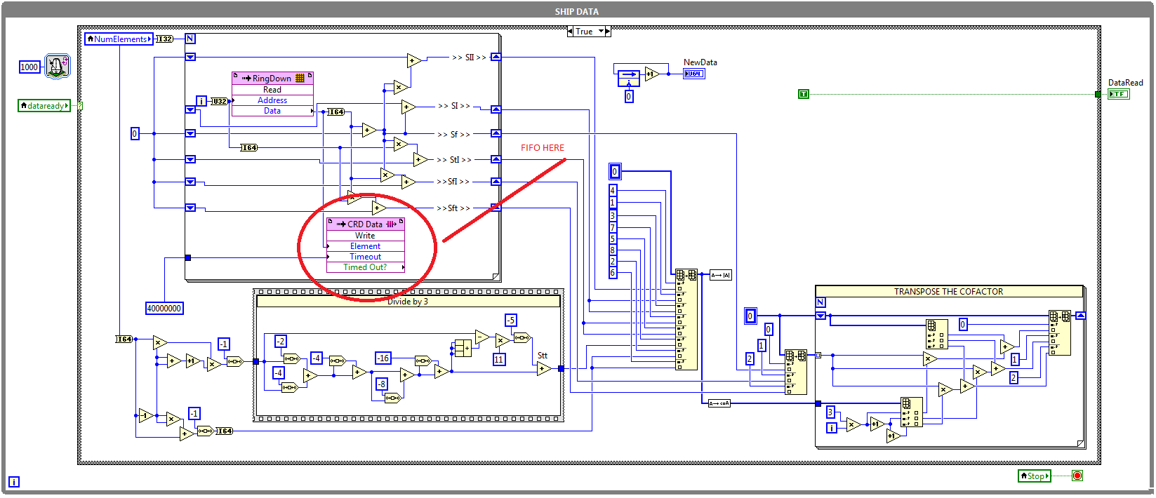
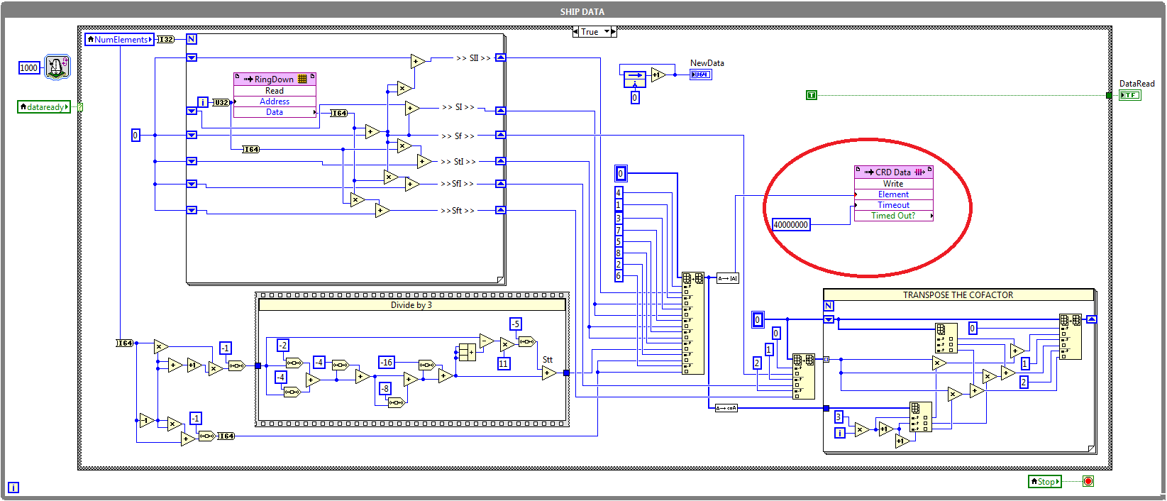
I have another problem when trying to write the data to a table. Even if my method of reading does not expire, I don't think that will record the first beam of data that are read. I've initialized an empty table outside my acquistion of the side loop host and used the table VI build to take the current data set and add it at the end of this table. I then store in a shift register and pass it in the next iteration where I try to join the new data set to the old and so on. I expected to get a table with all the data, but as I said I'm only collecting the first set of 500. I wonder if my program structure is correct. Any help anyone could offer would be greatly appreciated. I have attached a few pictures of my reference request. Thank you.
Hi Daniel,.
Thank you for your response. I think I found a solution to the problems that I had. Looks like it was a combination of a couple things. First, the data acquisition loop was running not until the movement was already over since I plugged the condition to stop the loop of writing deposit directly on the data read loop. This problem has been fixed by creating a shared variable for the stop condition and it wiring to two loops independently. This explains why I got only the first set of data, as it was stored in the FIFO until the end of the movement. However, the FIFO of feedback was still time. Before attaching the stop condition error, I placed a probe on the "items remaining" wire of the read method and concluded that there was only 1023 elements (the depth of the FIFO on the side FPGA) even if I set the FIFO depth host side to 60000. "» I realized it was originally due to the Read method not called for the first time until the end of the movement. Although the problem of break for most fixed condition this problem given that the Read method was now called during the movement, I decided to take a preventive measure and calling the 'Start' before the movement FIFO method is started just to make sure that the memory of PEP on the side host is available immediately.
So yes, it turns badly I put sync settings have been well after all. Good call on the reversal of the order on the Array function to build. Oh, and I also had to move the waveform diagram to until the table is built so that it is not Replot the old data on top of all the new data it receives. On the same note, I moved to the indicator in table at the end outside of the loop of reading. Thanks again for your help.
Kind regards
John has
-
How to choose the maximum number of items for DMA FIFO to the R series FPGA
Greetings!
I'm working on a project with card PCIe-7842R-R series FPGA of NOR. I use to achieve the fast data transfer target-to-host DMA FIFO. And to minimize overhead costs, I would make the size of the FIFO as large as possible. According to the manual, 7842R a 1728 KB (216KO) integrated block of RAM, 108 000 I16 FIFOs items available in theory (1 728 000 / 16). However the FPGA had compilation error when I asked this amount of items. I checked the manual and searched online but could not find the reason. Can someone please explain? And in general, what is the maximum size of the FIFO given the size of the block of RAM?
Thank you!
Hey iron_curtain,
You are right that the movement of large blocks of data can lead to a more efficient use of the bus, but it certainly isn't the most important factor here. Assuming of course that the FIFO on the FPGA is large enough to avoid overflowing, I expect the dominant factor to the size of reading on the host. In general, larger and reads as follows on the host drive to improve throughput, up to the speed of the bus. This is because as FIFO. Read is a relatively expensive operation software, so it is advantageous to fewer calls for the same amount of data.
Note that your call to the FIFO. Read the largest host buffer should be. Depending on your application, you may be several times larger than the size of reading. You can set the size of the buffer with the FIFO. Configure the node.
http://zone.NI.com/reference/en-XX/help/371599H-01/lvfpgaconcepts/fpga_dma_how_it_works/ explains the different buffers involved. It is important to note that the DMA engine moves data asynchronously read/write on the host nodes and FPGAs.
Let me know if you have any questions about all of this.
Sebastian
-
I want to transfer data to my FPGA using a DMA FIFO. The FIFO is 1024 elements, but can I write bigger than that of the side pieces PC? I don't know if the PC actually allocates a larger block of memory for this purpose?
I'm sure that you can set DMA on the side host is greater. There is a node of configuration DMA you can use host-side to define the size of the FIFO on the side host. The size is set in the hardware on the target side.
-
NEITHER 9234 fifo dma file samples
Hello
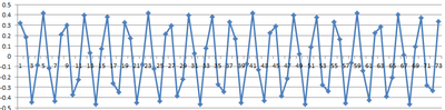
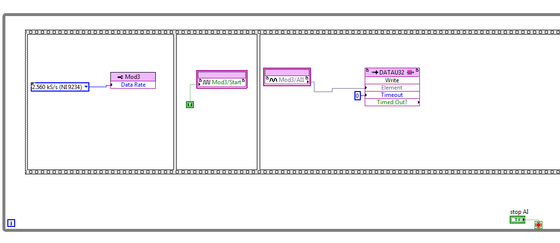
I have a problem when sampling using the cRIO and map AI NI 9234, currently configured to sample a signal of Hz 1 k of the side signal generator FPGA goes directly to the DMA which is (1023 elements in size) on the side of the host (size of the element 1 million). With the help of the producer, architecture of consumption and saving on PDM on the consumer side. The producer has read dma fifo. Please see pictures any help would be great!
If I plot the data, I get this:
Here is my code FPGA:
Here is my version of the host:
Hello
The problem has been resolved on this post.
Thank you
-
Hello / Hello
I try to pass some trought DMA FIFO data, but I have a timing problem.
I hope to read on rt 0 as 1, 1 as 2nd etc...
Any idea?
I test data paser (0,1,2, 3.6, 7) since an FPGA to a RT but I can't read the data into an orde fixed kind, the then 1 0 en 1 etc...
Any idea what's wrong in my code?
BR/thank you
Found!
I read 100 element and write 8 by 8 element, 100 is not a multiple of 8.
read 80 work item
-
FPGA FIFO (reset and stop) release
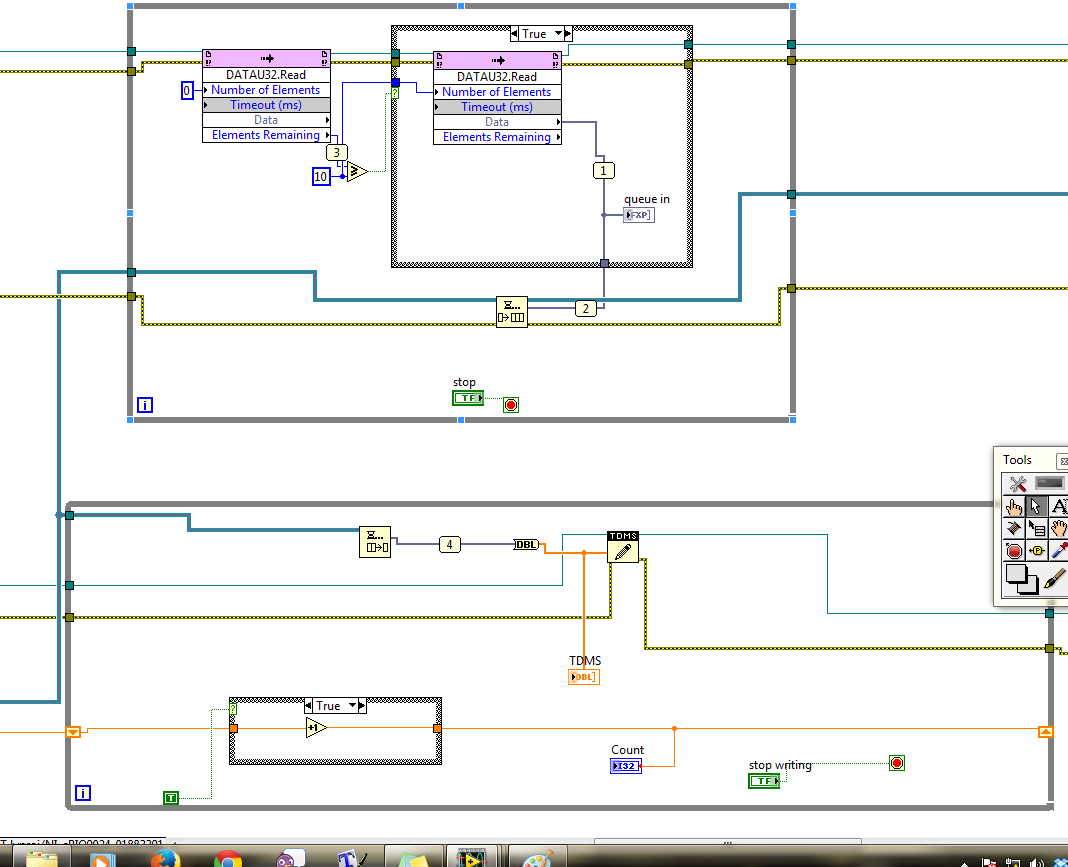
I have a question regarding the release of FIFO. In VI, I use for the collection of data through DMA FIFO, before collecting all loop, I use FPGA reset and after the while loop, I use FIFO.stop. I have attached the picture. However I think it is the last great of data I have collected and wrote in a text file of a single keystroke, appears in the second run, after I stop vi (by Boolean JUDGMENT in vi) and then restart the vi. Seems the data remained in a certain part of the FIFO and has not been emptied by RESET or FIFO. STOP the service. Is there something that I did wrong? Is there some FPGA or the vi setting I know not?
Thank you very much!
OOPS. I solved the problem. It has nothing to do with the FIFO. I need to empty the table at the end of execution so that it cannot be read and written to the file that I use for recording data. Thank you very much anyway.
-
Read and write in two separate FIFOs DMA on RT host
Hello
I have two parallel loops running on a host of RT on a CRio9022. There are two DMA FIFO: one of the FIFO is written for in the upper loop, another FIFO is read from the bottom loop. I've attached a screenshot of my code.
The problem I encounter is that I seem to be only able to run one of these loops - for example if I disable the first loop, I can see data through the second loop. Trying to run them in parallel because I think I've coded it means only one of the tracks-it loops is always the top loop in the code that I have attached the screenshot. Each of the FPGA VIs that run only use a FIFO so I think they should be able to run independently... I was wondering if anyone could shed some light on this?
Thank you
Hello.
You can only have a single call to the FPGA in HOST mode, the algorithm that you post, that is make two calls to the VI 'Reference of VI FPGA open', this is not allowed, this is why the program works only with one of these cycles.
Kind regards.
Maybe you are looking for
-
How to remove a page number for a specific page
I am editing a book of poetry in pages and my start of document with a title page, followed by a couple of blank pages, followed by the table of contents pages followed by the rest of the book pages. Now I have whole page numbering upwards in the fo
-
Elite book 8570p: ID PGF16J failure Diagnostics - 00082 B-MFKSXG - 608K 03
The HP hardware HP Diagnostics UEFI running at startup I get the following:INTELLIGENT control: FAILUREFAILURE ID: PGF16J - B-MFKSXG - 608K 03 00082PRODUCT ID: E1Y27UT #ABAHard drive 1
-
How to disable text-to-speech (TTS) on moto cliq 2.1.5
Good so I was sleeping with my settings and see TTS, figured hey what's - do this, installed the voice synthesizer app and then implemented. After I received a phone call from a friend and the TTS began to say the name that is not what I want at all
-
Strange temporary freezes everything by playing games?
It all started about a year and I have still yet to find a solution. I have a Dell XPS 410, and the only thing that I replaced the graphics card is recently. anyway. So, I play many MMOS, and would really damage my gameplay and the fun of the game. B
-
App Uploader hanging on the file download
Everyone has a problem with uploader suspended just after the file is supposed to be downloaded on the vendor Portal? I make it as far as this screen and you can get no further. I tried in Firefox 3.6 (?), 4.0, IE9, IE 8 with no luck in one of them.