oversampled
It's really just an annoyance but muse has decided my site has four images which have been oversampled and whenever I have throw the muse or go to publish the muse keeps reminding me to fix. OK, so I put four pictures until the error message came (but I deleted a slideshow with four images!) and the active panel shows all the oversampled icons. I'm stuck with this error for ever?
Images, used as ' shall' (browser fill, background fill, fill of the object)) are momentarily not alerted in the active panel, if they need to be oversampled.
Tags: Adobe Muse
Similar Questions
-
Oversampling in CS6 or resize perfect 7.5 vs scan at higher resolution
Hello
"I have a lot of images of landscape (holes of golf) which are 1600 x 1200 pixels and I would like to be able to print to a frame size of 8.5" x11.0 "with 300 dpi.
I'd be better to use the features of the CS6 or resize them perfect 7.5 (I does not currently have this software but can afford it) resampling to "rate" the image or scanning smaller prints (4.0 "x5.3" at 300 dpi) with a greater number of pixels and then re-print images to the largest size? Notes; I have an Epson Perfection V750M Pro scanner which is able to 6400 x 6400 scans.
I realize I can get a free 30-day trial of the perfect resize 7.5 but I would try the forums before I left for the problem of downloading and using this new software and then comparing it to images digitized and pulled apart of thought. This forum is much faster with the participation of the users, which I am not!
Thanks for the tips.
See you soon,.
Mel
Sorry, I consider generally 1600 x 1200 (2 megapixel) of a low resolution image (Yes, think of pixels in total). And I don't think I'm far away, because you want a 11 x 8.5 print. I usually work with files from digital camera oversampled order 6144 x 4096. Today, I was working with a 50 astroimage + megapixels. Everything is relative.
I have nothing else that to move your image with the perfect oversampling process 7.5 resize 3399 x 2549 pixel (8.5 x 11.33 inches at 300 dpi). Registered quality JPEG 9, because level 10 made the file too large for this site to accept.
Perfect resize is decent for images with lots of natural content, like Fractals card pretty good nature. Just keep in mind, it does not replace real detail.
-Christmas

-
Sometimes I chat with my clients and colleagues that we get a quality image of the F5 because we get the 1920 x 1080 sensor 4K low - or sur-échantillonnés.
But in turn almost always bringts upward the objection and then the 4K image can not be good at 4K

When RAW is really RAW, and then we have 4096 x 2160 pixels and not more, right?
Demosaicing is made from those. Or is it more in the background who see us not?
Thank you!
__Peter__
I would say it's true in a sense, this is the reason why the F65 uses more pixels to produce a 'superb 4 k image '.
I don't know that the resolution in pixels has never specified for RAW before debayer, but what is the megapixles of the F5 or F55 again? Which could lead to an indication.
-
Smart oversampled images can print?
I want to enlarge a photo of 300%, that will be printed commercially. Anyone who has used this function successfully.
The new upsampling is kind of new. It was introduced when Photoshop CC came out. (It was in 2013? My old mind... I lean over and memories fall just to the right of my ears.)
If I had to venture a guess, a 10 inch interpolation does not look bad at all. Nobody will go right up to the poster and look at the points, to be honest. Posters were meant to be looked at from a distance.
-
Hello
Very recently, Photoshop CC (v. 2015 - 0-1) stopped upsampling to get my photos. As soon as I have high-end image, the result is either a black canvas or random pixels. Subsampling works very well.
Someone knows something about this subject and know what to do?
Your help would be very appreciated.
Thank you.
To update your graphics driver or disable hardware acceleration.
Mylenium
-
RFSG - generate Modulation DTMF
PXI: 5670 RF Vector Signal Generator 2.7 GHz (5621 ARB and 5610 Upconverter)
5421 ARB
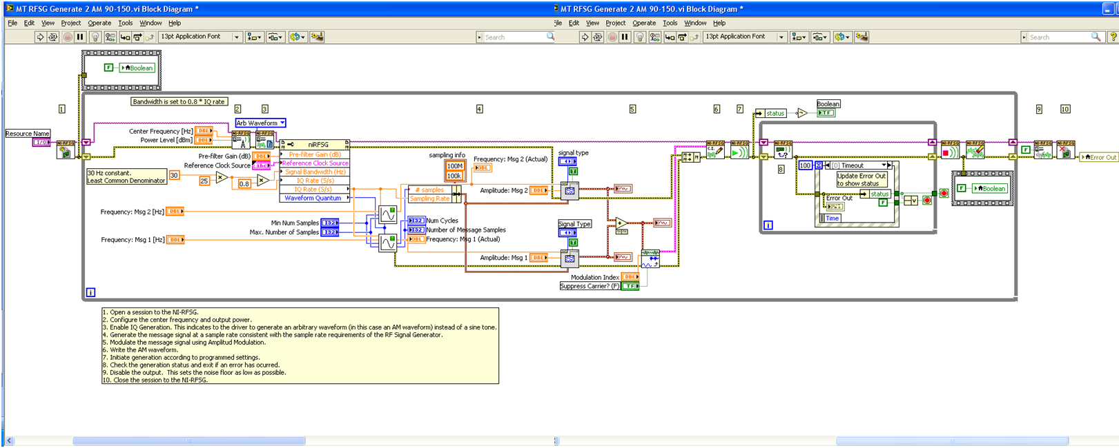
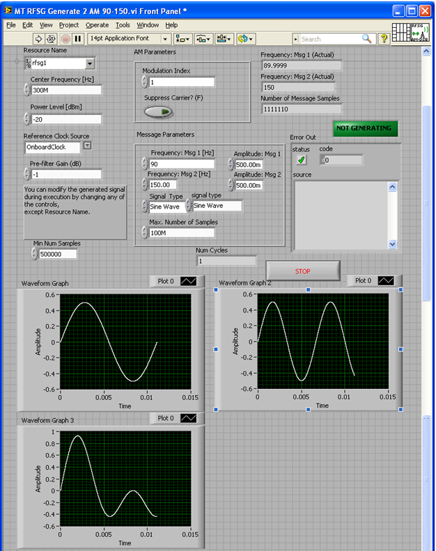
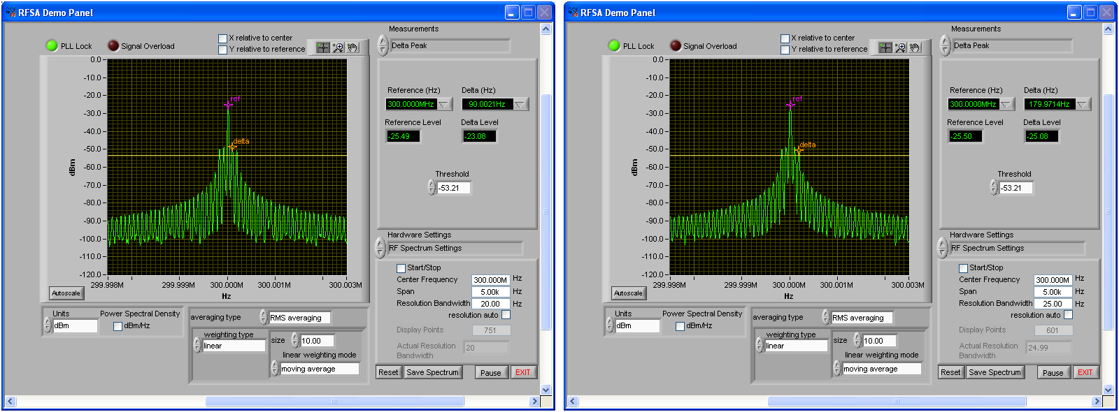
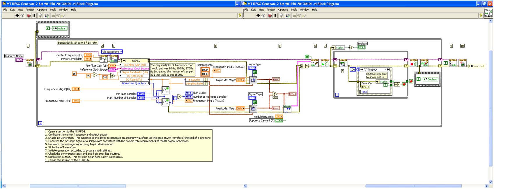
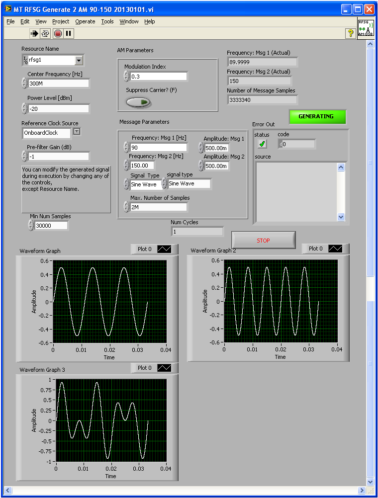
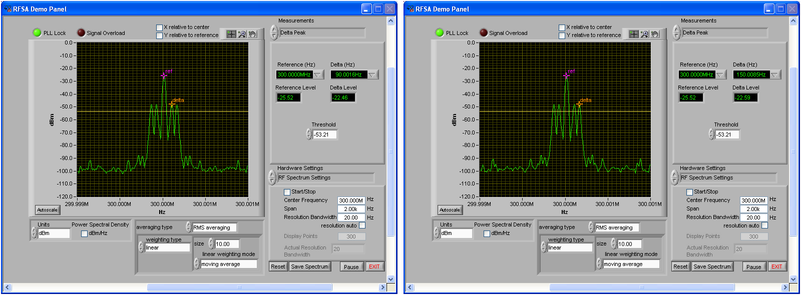
My goal is to generate a modulated signal - dual-tone with 90 Hz and 150 Hz carrier modulation of 300 MHz. It was built with examples of how to include the two tones, but I couldn't get the second tone at frequency, I said to (it was only a multiple of the first images of frequency - see). By increasing the number of samples by 3 before generating the sinusoids, I think I managed to do work, but I can't explain why I was getting so many Spurs, or why "compel him frequencies and Subvi samples' (a right after the node property) does not take care of it. Why should I this hard-coding? Will this work? Any information would be great!
Hello regulator,
In my view, that it is a sampling problem. You take the number of samples in the 90 Hz signal rather than the 150 Hz signal. 150 Hz signal need more samples to represent accurately, so this number of samples increased from 90 Hz is not enough. When you multiply the number of samples by 3, you simply oversampling. It will be a little more taxing when you do the modulation, but it's okay as long as your machine takes care of everything.
Concerning
-
Example of signals with a filter anti-aliasing
I use PCI-6259 6221 PCI and USB 6221 cards in different configurations. As I understand it, is that the anti-aliasing filter on all of these cards is fixed to pass to the frequencies of 1 MHz. If I'm a signal from a RG58U BNC cable that is supposed to contain higher frequency of 1 kHz sampling, but there is noise of high frequency present there. A sampling of the signal to 2 kHz would be enough to acquire the signal correctly, or these high frequencies would affect the components of low frequency on sampling?
I read about too much sampling that allows you to use digital filters (I'm guessing that software filter can be used) If you sample the data at a higher rate. You should always use the anti-aliasing filter, but the required parameters are more relaxed. Would this work in my case? The anti-aliasing filter on my cards has a very high bandwidth, so I don't know how much I need to do to acquire the signal correctly oversampling. Is there an equation?
Also, if the analog inputs for data acquisition cards are generated by a filter (for example when recording ECG or EEG) which allows you to specify a bandwidth frequency, I still need a filter anti-aliasing? Would be the distance between the amplifier and the DAQ card much a difference when it comes to the generation of noise on the cable?
In general, I try just to see if my current collection method at the rate of Nyquish with the maps I have is good or not. I just save the data without even using any digital filtering (software).
That's right - if you go down to 10kS/s then the temporal resolution and minimum pulse detection would 100us. If it is a just sampling rate or not depends on your requirements for the accuracy of timing and jitter. In other words, if it's OK that your pulse Detection could could delay until 100us then a 10kS/s sampling frequency should be OK.
-
Requested sample clock source is invalid wls-9163
My goal is to use two accelerometers that using the NI 9234 entry of the modules and wireless wls-9163 chassis.
My program is attached. Here is a photo in case you do not want to download the attachment: http://www.imagebam.com/image/577a4a195651371.
The slave device is not able to use the sample clock that came out of the master on PFI1.
I looked through the wireless DAQ resource kit and watched the following video:http://www.YouTube.com/watch?v=g_8jiKuKeDI
and ive read this: http://zone.ni.com/devzone/cda/epd/p/id/6124
I am aware that
I also tried to synchronize two cDAQ-9178 using the same methods. I always get the error "required sample clock source is not valid.
The manual says it should be able to do this
http://www.NI.com/PDF/manuals/372488c.PDF
Any help would be greatly appreciated.
Vexis,
Unfortunately, at the moment, you cannot synchronize the modules that use adelta-sigma converter (such as the NI 9234) in several cDAQ chassis. This is because these modules use a clock of sampling, which is very high; the PFI lines are unable to return to the required sample clock. You can share the start triggers, but the clocks of individual modules will drift over time.
The reason that the error message says that "requested the sample clock source is not valid" is because these modules require the use of a sample of clock that comes inside a time base clock oversampling.
Sorry for the bad news!
Katie
-
Configuration of the basic Source of time to master for the 9234
I have several cDAQ modules I use to collect data. I use vi to Write can Express to save data to a file of PDM.
When you examine the recorded data files, the measured data from NI 9215 provide pleasant timestamps to match how the DAQmx task has been set up--delaying the sampling frequency of 1000 with a 1 ms in the While loop. However, although in the same vi - different tasks, but the same while loop - horodateurs of the NI 9234 do not correspond to the task of DAQmx implemented - sampling frequency of 1000 with a 1ms delay. After reading the material provided with the NI 9234, I found that maybe the machine clean master Timebase Source. There were documents that says he can be configured to be originally of Timebase of Master for the other modules:
Configuration of the basic Source of time of the master for the NI 9234 (Interface FPGA)
It is desirable to have the timestamps for data measured across all modules to match. We do not have the FPGA Module for LabVIEW. Is there a method in LabVIEW for all modules use the same master time base Source? I assumed that because all the data collection has place in the same while loop by using the time delay of 1 ms it was forced through the code. This hypothesis seems incorrect from my review of the PDM data files.
The NI 9204 provides a trigger only.
Software:
Windows 7
LabVIEW 2010 SP1
Material:
CDAQ-9174 chassis
Slot 1: NEITHER 9204
Slot 2: NEITHER 9215
Slot 3: NEITHER 9234
Slot 4; Vacuum
Hi MgDAQ,
An important concept to note is that the 9234 uses a delta-sigma converter and a clock of oversampling to read analog data. There is an inherent delay of entry due to analog and digital filtering built-in. Since the 9215 has a lower resolution there will be a lag the 9234 and 9215 finished. I've included some resources below:
What are the for the NI 9233, NI 9234, and NI 9237 valid sampling rates? : http://digital.ni.com/public.nsf/allkb/593CC07F76B1405A862570DE005F6836?OpenDocument
Synchronization of DSA, S and X series devices with a NEITHER-DAQmx single task series: http://digital.ni.com/public.nsf/websearch/78E44565FD87E7D686257108007F94F8?OpenDocument
Synchronization with NOR-DAQmx of acquiring dynamic signals (DSA) products:http://digital.ni.com/public.nsf/allkb/A133ED27DF9BCC5986256F2E004BA342?OpenDocument
Have you tried to put two modules in the same spot? Alternatively, you can export the sample clock 9234 and tasks installation separately.
Best,
CARISA
-
Min/max to accumulate dasylab peaks? Is this possible?
In collaboration with Dasylab 10. I'm looking to collect peaks min/max on a form of sinwave we will run. Is this possible? If so, how? Or I have to just to oversample and sift through data?
Thank you!
Select this option.
Use the statistics module called Minimum / Maximum.
This will display the value (you choose minimum, maximum or both), or will display a TTL signal, with a peak TTL (5V) to record highs.
Adjust the hysteresis value to avoid detection from noise and spikes, or use a moving average to smooth out the signal.
-
variables of user-defined data transfer
Hello
I use the etherCAT 9144 chassis and is only supported by this hardware FIFO range target. After a search, I realized that the only way to transfer data from FPGA to the host by using user-defined variables. But these variables do not support the notion of FIFO. So which is the best practice to transfer data after measures (provable 10 Hz measurement of 15 values) to host VI?
Thank you
As mentioned, the 9144 only supports the analytical engine.
In regards to what you do, it really depends on the entire application. For example, what is the master? Are there other systems at issue here? Etc. It's a good read, in general, although it might not help this second right: http://www.ni.com/white-paper/14151/en/
A high level, you need to decide what you need. If you have need for deterministic communication, low-latency over long distances from a RT controller, the 9144 is probably the right choice. If you need low latency + streaming over short distances to a RT controller, you should look into the RIO MXI chassis. If you need mainly not deterministic low speed (10 hz) data mixed with low flow continuous over long distances to a windows or host RT, then ethernet expansion rio (9146,7,8,9) is probably the right choice. If you need high speed continuous with low control latency over long distances to a windows or RT host, you need a full cRIO controller. Based on what you've posted so far, its uncertain is the right person.
Lets say you're stuck with the 9144 for now. As you can easily hit 1 kHz scanning cycles, it should be perfectly possible to data 'stream' to 10 Hz. If you run the scan at 1 kHz engine, then you are 100 x oversampling. Where it gets complicated is this requirement of sync. By default, acquisition input/output is synchronized to the clock of the scan (and you can see when the clock of scan is set by a knot of e/s FPGA). However, you can take complete control of a module in the FPGA and read inputs and outputs at any time if you please. In other words, you can set up so when DIO0 goes high you immediately enjoy all the values of AI 15. You can then transfer these values HAVE switched to the host using the user-defined variables.
-
Program vi to turn the lines Testpanels HSDIO
Hello everyone,
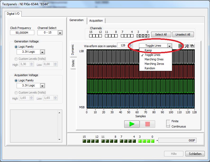
I have a question about HSDIO testpanels in MAX. There is an option to MAX to generate the data in various forms of digital data:
RAMP / TOGGLE LINES / THOSE WORKS / MARKET ZEROS / RANDOM.
And most of the examples using HSDIO generate data using the method of the RAMP. I tried to look but I couldn't find other methods of data generation. I really need the program to generate the data with the method of the LINES of the ROCKER. Have tried to use the block express gen, but does not help me either. In my view, it should not be a complex built in the program, but somehow I don't see what I would do to generate this signal. I need two channels to generate the same signals as in the picture above.
I tried to build the ramp and a channel that connects with another a channel not used, but the voltage has dropped and so I don't want to use this method. Later, I may add delay to a channel, but I think I can get something of an example of NOR (dynamic generation with a delay of data).
Kind regards
Yan.
Hi Yan,
To get the clock frequency of 1/4 on two channels, it would look like this:
00
00
11
11
00
00
11
11
You oversample data and then you get two channels with frequency of output 1/4 clock rate.
-
Hey,.
is it possible to use NOR-8452 two being as master and slave?
Thank you
Dear Grega!
You are right, function slave SPI is not supported on the 8452, because he will always provide clock and chip select signals as outputs. There are a few things we can do to solve this, depending on your resources and demand.
a. use the FPGA as a slave module, because that is supported. If you test the master behavior, however, it is not applicable.
b. oversample the FPGA output. You will use two devices such as masters so that they will not be synchronized, but the SPINNAKER needs no acknowledgment of the slave to the data transfer always works this way. Data redundant, created in this case (since USB has to run to not miss anything, so some data will be measured twice) should be somehow removed programmatically.
c. use any DIO module that supports the edge to act as a slave device detection.
If I understand, as we will collect data to measure the FPGA, two-way communication is not necessary, just read what the master module written on the bus. If it's not true (you want the slave to react in response on the bus), so only a good slave SPI (FPGA another perhaps) is suitable.
Kind regards:
Andrew Valko
NEITHER
-
SingleToneInformation detect nearly 0 amplitude to 0 hz
Hello
I use the 4071 DMM AND measure some AC signals. Sometimes I'm also trying to detect the absence of an alternating signal n (stable switch). My automation is all c#, I find it acquire a waveform and dealing with SingleToneInformation much faster to just have the built in a measure. By customizing the rates and the number of samples, I can reach 20 X faster measurements (and quite right too). This works really well if there is actually a signal. It doesn't work so well when I check the absence of a signal. The class SignalToneInformation spits some garbage values (like really high voltages that my system could ever generate). Sample data is fairly thin with typical background noise usually well below one. Millivolt | and no corresponding samples to not return the value (I got 500V return values when no sample was more than ±0.0009. What I do to work around these bad values is simple process the sampleData for | pics | (enter the Max AbsoluteValue).
Two things:
(1) class (Analysis.Enterprise) SingleToneInformation should do a better job handling a no signal condition.
(2) in my test, I know when to wait for a missing signal, but there might be cases where I don't know and I want to measure. If she were to measure a signal-no, I get garbage. I should be able to have either SingleToneInformation give better values or an indication that he couldn't catch a tone with success.
I'm testing a system that generates signals AC using a DAC. I always test type single tone signals (usually a form any of a sine wave.) I still have a lot of oversampling
My software is up to date as of May 2, 2013 accoring to OR update.
Thanks for your help!
Hello JohnGardner58,
Currently, the function extract a single signal does not notify when it cannot detect a sound signal. However, there are plans to implement these features in the future.
Digital Multimeters to take a second to determine the frequency, as it must have some cycles a signal to measure with precision the frequency. However, this period is expected to decline during the measurement of higher frequencies.
When I'm looking for rate data, I use the function extract a single signal. The Sound and Vibration Toolkit has other functions for the calculation of frequencies. However, all these functions will wait a frequency and no noise. I recommend the code to get rid of the noise of post-processing data.
-
Can we average channel error using multiple channels to measure the same voltage?
I don't know how correlated error terms are between measuring channels max, but it occurred to me that, if they were relatively independent, I might be able to sample the signal even with several channels and increase accuracy.
For example, rather than measure a voltage with an AI only at 100 kHz, I could connect up to 10 different lines to HAVE the signal, sample to 10 kHz on each line. This should allow to reach me on average some of the error associated with each channel (, or so I think).
Can someone speak definitively to this?
Thank you
Sean
Well, if you are using a MULTIPLEXED Board (everything is not specced for simultaneous sampling) then each channel is connected to the ADC even one after the other, best that you would be able to do is extremely, extremely small variations into the paths of each channel of the multiplexer. This would still be massively overshadowed by the inherent noise from the system and the accuracy of the device.
Your best bets to reduce the measurement error is to oversample in one way to reduce the effects of noise and to calibrate the unit before starting each test to keep variations of temperature. In addition, make sure you keep your calibrated Board (most of the boards have a calibration 1 year of the cycle).
For some applications, you should also consult wiring field and considerations of noise for analog signals, How to eliminate ghosting of my measurements? and Troubleshooting unexpected tensions, floating or crosstalk on Analog Input Channels to better account for ghosting and the issues of the hour.

Maybe you are looking for
-
Anyone having trouble with their Apple music always is on shuffle on their iPhone? Since I have updated to iOS 10 on my iPhone what I listen to some remodeling. I can't listen to anything in the order.
-
Problems using Modbus TCP accessible by NI OPC Server
Hello I use OPC OR server to access a module of measure. The accumulation is pretty easy, my system with NI OPC, modbus door and the module connected with RS485. There is a thermocouple to provide me with some examples of data. But there is the point
-
I have a TouchSmart from HP ENVY 14 t-k000 CTO Ultrabook. It just went on a month of warranty or if there is but begun rigth blue-screening after that - I had to reinstall Windows 8.1. Since the installation, my wifi works correctly. (I use an Ethern
-
My new U2414H I have a mass purge of backlight. The previous was already exchanged cause there was also a mass purge of backlight. Right now I don't know what do more. Here are pictures of the monitor. When I play games or watch a movie, the light is
-
Can someone explain how a 3750g which has been configured to use a radius server for authentication of access (to reconfig)? Just, we have installed a new battery and use the switches for other tasks. He continues to show the RADIUS as answers don't