peaks of waveform AVERAGEING
I take the data resulting in a form of variable amplitude sine wave, as seen in the joint. I want to normalize the wave to have an amplitude equal to the average of the peaks but cannot figure out how. If possible, I'm hoping to get a solution with components of LabView, because I'll do the tests of other parts which will result in different amplitudes and number of peaks. Thank you
Take your signal, he feed the Hilbert transformation function. Use the original signal as the real part of a complex signal and the result of Hilbert transformation as the imaginary part. Take the magnitude of this signal and you'll have the envelope. You can then means this signal.
Tags: NI Software
Similar Questions
-
Detect the PEAK, mount and average
I use a loop in LabVIEW 8.5 to capture the signals emitted continuously by a card, peak detector.VI is used to detect the signal peaks, then fit.VI nonlinear curve is used to climb the summits, signal now capture, detection of peaks, mount and display pics are all works very well permanently, but there are still some problems annoying me.
1. the received signals is not very stable, so editing results expected on average for 100 times, then how can I averaged the results of fitting on the condition that the capture of signal is not interrupted, this is the time loop does not stop, when the average is made this time, average is reset for the next 100 fitting results can be average again?
2. There is another way, that's 100 results of fitting is automatically saved to excel, then the results is an average manually in excel, then how to store results like this: the first 100 results of connection are stored in an excel file and the next 100 results for other excel connector or they are stored in an excell , but in different columns? Of course the thses are subject to the capture of signal is not interrupted.
3. There is a threshold for the detector.VI peak, but the captured signals entry isn't very stable, so the number of peaks detected is not the same every time, like this time, the number of vertices is 40, next will be 39, this will affect the results of fitting slightly, then how do to detect the same number of vertices every time such as the number is 40 each time?Any advice will be appreciated!
Maybe the pic attached detect.vi 'test' can help you. "medium signal.vi" is a sub VI on average the signal in a way online.
There are three methods using the input signal:
1. no average.
2. average exponential.
3. linear average.
Your problem is when the input signal is damaged by some noise, and you want the input signal before the detection of peaks on average. I use white noise to simulate a noisy environment.
By default, the average mode is 'Linear', and the number of averages is 50. The more averages, the best on the result, but more time to update.
Swith mode between 'Linear' and 'No way' to compare the difference before average and average.
Average exponential is not appropriate in your case.
Let me know if it works for you.
-
Detection of peaks of waveform data
Hi people.
It is probably obvious, but I can't understand it. In the attached VI sine wave detector summits are determined from a simulated signal. I want to be able to do the same thing with a waveform data (DBL), but it won't let me. How can I extract the signal of the LDM to feed the rest and make the waveform work VI right Ridge detector?
Thank you
Select this option.
Use of DDT, found in the range of Signal handling, to change the dynamic thread in a waveform.
Bob Schor
-
Average simple from a 2D array?
Hello world
I have a small speed bump with my vi; I hope somene can help...?
I have a chart 2D containing 6 signals (waveforms of the strain gauge). Need to calculate the waveform average 6 signals through while I 1 answer signal (waveform)... In matlab, I d code like:
mean_waveform = mean(2D_Array,2);
This has left speechless me...? Any help would be greatly appreciated.
Kind regards
Jack
Transpose the table, go in a loop FOR with a Mean.vi in there.

-
PeakDetector on top of waveform DBL
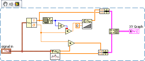
I have a waveform DBL I want to find the vertices. I have the feed in the PeakDetector, but cannot figure out how to place the output of the peakdetector on the same plot in the form of wave DBL. At the end of the day, I want data peakdetector to output to a data file with the same time-domain in the form of wave DBL.
Here is a picture of the current situation.
Thank you!
Hello
You can use the XY graph to plot locations detected PEAK and waveform input.
Please see the code.
Best regards
Michael
-
Analog output DNL value details
I have an application where I use a card PCI-6221 to generate a sinusoidal signal over a wide range of amplitudes (> 1000: 1). Obviously at low amplitudes, the waveform becomes very pixelated, but the harmonics generated by it are not a problem in this application, and I found that the use of a small number of steps of the ADC has surprisingly little effect on the amplitude of the fundamental.
What is potentially more of a problem is the DNL specification of +/-1LSB. This means (I think) that if my peak-to-peak amplitude waveform is 65 CAD not and he is riding on one of the glitches in the stairway of the DAC real amplitude might actually be steps 64 or 66.
My questions:
The DNL value technical or worse is stipulated in the average of plug? Since the device has guaranteed the monotony I think there must be worse, in which case there is no data on what is the distribution of the DNL error?
In the DAC in the 6221 the biggest mistake step usually gets to the point where the MSB changes state, which would usually be close to the point of zero?
If so, it would be useful to define the range of output + and - values to asymmetric tensions so my waveform is not sitting on the MSB switch point?
Thanks in advance!
Chris
Hi Chris,
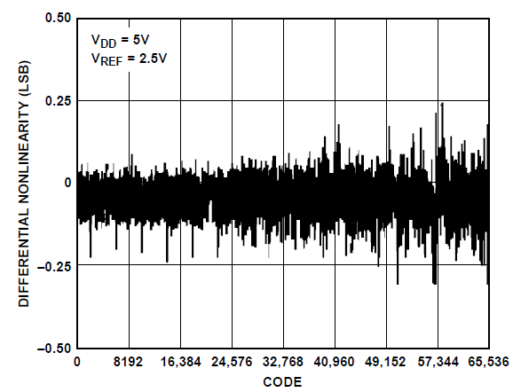
You are right that the DNL worst case is ±1 LSB (where the guaranteed 16 - bit montonicity mentioned in the page on record). This is a 'classic' of the DAC manufacturer DNL distribution:
As for your second question, glitching may appear when the value of the DAC. This parasite is not included in the DNL specs (which represent a queue time). You are right that the most important glitch occurs when changing the most significant byte of the DAQ hardware (which is approximately 0V on the 6221, calibration function). Glitch is accounted for in the specifications OR as "Glitch energy" (see page plug link above), and you'll probably notice the value is relatively high on the 622 x. The 625 x and x 628 have much less power glitch due to the use of a different DAC.
If I understand your third question, the idea would be to adjust the range of the 622 x so that change MSB does not match 0V? Unfortunately, the 622 x only has the simple bipolar ±10V range available, so you can not adjust the range change where the MSB. You can, however, the power of the wave with a DC offset so that the MSB is never crossed, then use a filter to remove the continuous component of the signal (assuming you want the sine wave that is centered around 0V).
Best regards
-
feedback loop on the impact force
Hello
I use labview 8.5 and a card Ni USB-6221 to control the power output of an actuator and monitor the output signal of a load cell. The actuator allows strength 50 Hz which is measured by the sensor.
The signal from the load cell is basically a very narrow peak occurring at a 50 Hz. I want to measure the height of each peak, average figure (maximum strength varies from 2 or 3%) and then use this data to provide a feedback loop to keep the constant force applied.
[img] http://farm4.static.flickr.com/3067/3077344302_4b7bb5f2a3.jpg [line]
I tried to use 'amplitude and levels' vi 'peak', for an average to exit mode. However, this seems to give a result fluctuate widly which is useless for feedback purposes. I tried to increase the sample of this vi period with no luck.
Anyopne there any suggestions on how to do this? I could do this using the detection of peaks of waveform?
Any help or advice would be greatly appreciated.
Thank you very much.
Hi John,.
Thanks for your post and I hope that your well.
To create a circular buffer in LabVIEW, you can use a shift register. However, for large number of data points with a large displacement to register on the side of the loop are stupid and impractical. This is why you must use a table, in which you update the value of the old with the new value, and you set the size of the table for the number of points you want to have in the buffer.
I have created an example of a buffer in LabVIEW 8.5 - Please see attached VI.
Also, if you do any static anylsis so perhaps consider using the functions of point by point, which no longer require the updated value to calculate the most recent average (for example). This saves because of the calculation table in its entirety every time.
Hope this helps,
-
Hi all
If I have a sin-wave captured from an oscilloscope labview went from zero to 10 seconds, how can I do to make labview will tell me all the time when values is exactly 0?
I have explored the peak of waveform detection.vi, but do not get back useful. What is the good vi? If so, how can I do return useful data?
If this is not the case, can someone point me to the correct vi?
Thank you
From table Y of the waveform. Run it through a loop containing a = 0? comparison. Outputs true mark the presence of zeros.
However, to compare numbers floating point zero (or any other value) is not a good idea because of the resolution finished in the binary representation of numbers in the computer. It is better to compare them to a small chain around the desired value (for example, zero). You can use the stove and Coerce fucntion for this. A constant predifined called 'Epsilon Machine' represents the smallest value between the adjacent numbers on your computer. It might be appropriate to use a value from the size of a least significant bit on your oscilloscope because that represets the error of quantization in your process of tracer.
Another way to find zero crossings is to locate points in the waveform where the adjacent elements in the array have opposite signs (if no items near the zero Lorraine are exactly equal to zero).
Lynn
-
Playback will not play properly?
When I go to my video playback, he keeps as jittering so I can't really change it. It this video is my internal Park so I really need to work. So if anyone can help me, please do
Thank you
This is copied & cleaned up a little, the Tweaker page, the authority on the development of platforms for publishing with Adobe digital video applications...
With all the reading and writing underway, on the startup disk, it is understandable that you need a dedicated disk (s) (number of) for video editing, especially with the bandwidth required when the length of the clip is short and the number of titles exceeds and uses a codec more complex than DV. The kind of files that are used during editing are, in order of their need for speed:
1. cache of media & media cache database files, created on the import of media in a project.
(They contain indexed, consistent audio and files peak for waveform display.) Generally small files, but a lot of them, so in the end, they still take up a lot of disk space.)
2 files (made), created during the timeline preview is performed for the purpose of the preview, the red bar turned green.
(These are played all the time when previewing time line and are written whenever you make a space for the creation of the preview).
3 project files backup project files, automatic that constantly read and recorded as written and automatic backup files when to save your changes.
(Many of these two reads & writes, but not quite as much as 1 & 2 above.)
4. Media files, original video material ingested by band or a card based cameras.
(Usually long, but a one-way process of read-only files non-destructive PR being an editor).
5 export files created when the timeline is exported in its final delivery format.
(A one-way process write-only, these files are usually only written once and often vary from several hundred KB to a few tens of GB.)
Note that the 1, 2 and 3 are all processes of reading / writing that requires a LOT of bandwidth & disk, while 4 and 5 are two unidirectional processes.
For simple speed, with some laptops seen say the media temporarily moved to a 'work' flash drive and make exports to another flash drive can help take the load off other resources... but you must of course, test as if two ports are on the same bus to the motherboard (motherboard) connection Well it's not quite as smooth as it might be if they are on the bus different mobo.
Say, you have three total discs with "decent" connections, (OS/programs) C, D, and E. It is often suggested that 1 & 2 above go on drive D, and 3, 4 and 5 GB on drive E. Although some find best results if exports (point 5) light up on the C drive... that if it's a large SSD could make sense.
Basically... There is a framework for you to test things on your system. With all the variables out there, no one can give you an exact step by step which is the best for your machine, the media, and work practices. That's what I wanted at the beginning and it was frustrating that the best advisers here do not give me a. Over time, I realized of course why they could not, and why it is only a part of the process of learning to work programs to a final result.
Neil
-
Help in establishing an AE/first effective workflow.
I work on several AE/first projects on a Pavilion M6 laptop and have a few drives that I use for storage/cache/export media and wonding what will be the best way to use each of them, or if I have to. My internal drive is a Sandisk SSD / 3 Gb/s, my second drive is a WD MyPassport 256 GB USB 2.0 5400 RPM HARD drive and my third is a Cruzer Sandisk Extreme 32 GB 3.0 USB flash drive. I'm on a HP Pavilion M6-1035DX if you need the system specs to make a decision. I currently have all my files on the MyPassport (because the extreme Cruzer flash drive isn't there yet) and wonder if I should:
- keep the media files on the MyPassport, run AE & first (and store the cache) on my flash SSD drive internal and export to the extreme Cruzer (when it happens here)
- or, move my project files and media at the Extreme Cruzer and run AE & first (and store the cache) on my SSD internal because the SSD is faster than the USB 2.0 drive (speeds of connection and read/write, USB 2.0 vs and vs 5400 RPS HDD SSD SATAII)
- or, move my project files and media at the extreme Cruzer, run AE & first on my internal SSD, and store the cache on my MyPassport (so it is not on the same drive as my project files, programs, or support)
- or, another configuration that I didn't think
I have a lot of places that you must use three drives for editing and motion graphic video, but because there are so many technologies and potential bottlenecks involved I want to make sure I do it right/effectively.
Of Page Tweakers - installation disc
With all the reading and writing underway, on the startup disk, it is understandable that you need a dedicated disk (s) (number of) for video editing, especially with the bandwidth required when the length of the clip is short and the number of titles exceeds and uses a codec more complex than DV. The kind of files that are used during editing are, in order of their need for speed:
- Database cache cache media & media files created on the import of media in a project. They contain indexed, consistent audio and files peak for waveform display.
Generally small files, but many of them, so ultimately they still occupy a lot of space. - Created during Preview (made) files of the timeline is executed for the purpose of the preview, the red bar turned green. Read all the time during the preview of the time line.
- Project files, including backup project files, automatic that constantly read and recorded as written when and automatic backup files save your changes.
- Media files, the original video material ingested from tape or card based cameras. Usually long files, used only for playback, since PR is a non-destructive Editor.
- Export files, created in the timeline is exported to its final delivery format. These files are usually only written once and often vary from several hundred KB to a few tens of GB.
-
Preparation more long tongs (interview) for a better overview? -Markers? Subitems? Etc. ?
Hello! I'm new to PP!
I work with clips more interviews (10-20 min) and I would like to prepare in order to obtain an overview on the passages of each clip that I could use for a sequence later. -At the FCC I could put not only markers in the source! window, but also change /name/ colorize them. So I would appoint several markers after the passages of text in an element in the source window.
Pp, seems to be only possible in the sequence window which is too late to get a glimpse.
Any suggestions? Subitems?Thank you very much for your help! -Michael
You can subclip for this, but I'm personally not a big fan of subitems in the first, so I generally do not use them. They act just... weird. I guess they are functional, but usually I find that when I try to use, I am limited and end up having to find workarounds. It is difficult to be more specific than that; I have been accustomed to subclipping in Avid that works much better.
Despite this commendation, if you want subclip, probably the best way to do is to load your source clip in the Source monitor, score points, and then hold down the Ctrl/Cmd key and drag the Source monitor Panel to a bin. This will display a dialog box allowing you to name the subitem and then slide the subelement in the tray. You can continue this way until you have created all your subelements.
As markers go, I think you're right: I do not think there is a way to add markers appointed to an element in the Source monitor. I'm not positive on this subject, because I have never tried to do. As far as I know, the only markers that can be named are trademarks of sequence. You can request a feature here: Adobe - feature request/Bug Report Form
My usual method of treating long interviews is kind of a subclipping hybrid approach. Basically, I create a sequence for each topic of the interview, and then either drop the full length interview clips in this sequence and chunk it upward, by renaming the segments I will or I load in the Source monitor and make the routine of starting and remove those in the sequence. Maybe it is lazy, but I find myself doing the first than the latter. It is easy to see where an interview answer begins and ends (usually) looking at the peaks of waveform in the audio clip. After that I have chunk on all the parts, I listen to just the sting and the name of the movie clip instance in a way that allows me to understand what the content of the bite is quickly. I then a workspace set up with two panels of chronology, where I can drag a piece I want to use in my editing work. I adopted this approach, after I have more or less me skunked by subclipping, and it's worked well for me. Of course, there are a number of ways you can go about this, so just experiment until you find one that works for you.
-
Number of averages for time waveform acquisition
Hello
It is on the configuration of the device - settings of the acquisition.
in the parameters of the collection file, can I know is there a way to feed the number of averages and % of overlap between averages aquire waving time.
Thank you!!
BR
Pattabi
In version 3.0 of InsightCM, we will support an average and overlap on the data of the spectrum Viewer. These settings will be applied only to the visualization of the spectral data and will not apply to calculations on the waveform or spectral data form.
This will meet your needs? Or are you interested in doing an average and are superimposed on the spectral data to then be used for calculations that are based on spectral data - such as 1 x Magnitude, etc.. ?
Thanks for the question.
-alan
-
waveform, with an average of results using labview to O-scope
Hello fellow engineers! I'm a first-yeargraduatestudent in CHEE at the University of Houston. Basically, I know nothing about labview. I am trying to program an application that looks like this - I collect a waveform of the signal of O-scope. This waveform does not change its characteristic shape. I need to find the wave form average of waveforms of N (100 for example). Thus, the slight changes (or noise) in the feature of form during the period mustbeaveraged out and I need to have a resultant waveform that represents the average waveform over a period. So, basically, I'm collecting the wave several times (for example 100) on a single period. The O-scope that I use now is Tektronix TDS 2024 B. It communicates with the computer via USB. The version of labview is 8.5. For now, I am able to communicate with the computer using our o-scope through labview. I already downloaded the driver of instruments of your Web site. It turns out that the program can give me only the average result I can get directly from o-scope manually. I need to have more say on average (100) using labview. I wrote a program that relies on the instrument driver that is downloaded on your website (for loop part is average, the waveform). The program that I modified and an instrument driver are attached. The program cannot be fully open, if the driver is not put in the right place in the labview (under lib inst.) When I run the program, the average waveform does not appear on the front panal and signal waveform file is not saved correctly. Is there someone can find where I did wrong and it develop for me? Because I barely know Labview, it will be even better if you can add an image or program that you have changed. I'm waiting for your creative ideas.
With the best regards,.
--
Weiye
-
With an average of 10 channels of waveform separately
I've written a VI that takes input from 10 different devices then shows in several graphics and then saves in PDM. This works perfectly well. The problem is, on my PDM data, is saving 25 samples per second creating a file of long worksheet for short durations. Im trying to figure out how to reach an average of each channel independently (average 25 samples) and print it out every second, so there should be a 1:1 ratio between my timestamps and data, not 01:25 how it is now. Thank you!

Personally, I just averaged 100 samples you take. If this simple solution is to replace your table decimate (inside the square structure) with a Mean.vi. You will need to use a range of build with a single input to transform a table to write in the waveform (still inside in Place element Structure) of the average.
-
Hello
I'm relatively new to labview and programming.
My goal is to acquire potential of the retinal, the signal I get is accompanied by noise and is within reach of micro volt, my goal is to average noise so that I can analyze the real signal (signal without noise).
The incoming analog signal is continuous, but I need to a window of time of 25 seconds alternative to the average value, which means: medium-sized signals of 0-25 s is not an average of 26 to 50 seconds, medium from 50 to 75 seconds and so on...
I started overwhelming with getting a signal from a function generator and averaging the full signal and displays the signal averaged over a second waveform graph. If the VI show all errors I wanted to know if I'm in the right way?
If Yes, then how can I do to average the data to 25 second multiple (for 25 seconds between the starting point)?
I've also attached a diagram of what I expect to see
I was thinking about something in this direction.
You have a buffer limited on the acquisition of your data. If you read fast enough, you will lose data. Then read smaller amounts more often. So I bibliography 1 second with a value of data 25 times.
Because you must connect to both average time, rethinking configure logging it, and just use the TDMS API instead. Do a search in the finder of the example (help-> examples find) for TDMS Wruite time Domain.vi. This is a decent example of what you want to do.
When you are doubt which category of files to put on what type of disc, especially when you use the SSD and HDD, remember that the speed advantage of SSDS on the HARD drives is most notable with the cache of media & media cache database. These files frequently access, are small and there are many, thus reducing latency and seek time and transfer increasing rate payer off the coast by putting them on an SSD, rather than on a HARD drive, even if it's a raid0. Export files can go slower on your system, since volume export you only once. To help you decide, I added row-numbers of priority for speed, for the fastest volume 1 and 5 for the less demanding category in speed.
Maybe you are looking for
-
Several Itunes accounts and libraries on a mac?
Hello all my current situation is as follows: My itunes and library account is on a mac book pro (I recently transferred my itunes library on an external HD connected to the extreme of the airport to free disk space), all works well My wife has her o
-
Synchronization FPGA or Subvi clock
Hello I have a Subvi FPGA that monitors for both events. I want a kind of trigger for the Subvi of output that I need to trigger the other screw (void) when these events occur. This means I can't leave my Subvi occurrences. I hesitate to use globa
-
updated my computer to windows 7 and now can not conect with the dns can not get online always
-
HP Officejet Pro 6830: How can I turn off Auto Save function before printing
I recently bought a new printer HP 6530 and configured using the wizard. Now whenever I try to print anything it forces me to save as a PDF doc before printing. I checked my settings and there is no 'save the doc' feature in advanced features. How
-
Vista Media Center DVD Player not to return to previous position
Hello and thanks. I have Vista Ultimate and I dive into the wonder that is Vista Media Center. It has a great feature! However, one of the points I noticed that lack is the DVD player does not playback from the previous position. As far as I know, th