Polar trace turn angle scale
Hello
Is there an easy way to manipulate the angle scale on a ground of polar? Specificaly I want to 0 degrees where 90 degrees is and then fill in the counterclockwise around the circle.
Thank you
Dan
I installed the following update sound and vibaration and I have the Polar VI trace to the 8.2.1.
I sounds like the plot of Polar VI is only in the more Sound and Vibration and not in the Toolbox.
Dan
Tags: NI Software
Similar Questions
-
The plot required is a polar plot to draw the objectives is to identify a radar detector. I traced a XY Chart with coordinates obtained remotely and measures of angles.
I want to draw this positions X and Y in the polar plot. Source to the XY graph is a cluster of 2 elements while the connection to the Polar curve needs a picture 1 d of the cluster. The individual data are table 1 d of double and make a bundle does not solve the problem.
Please let me know how to build the polar plot with distance and angle data.
Kind regards
-
Hi all
I have a beautifull with 2 columns Excel sheet. A column with the values in degrees and a column with values of dBm. I have my program to make a polar graph, but I still have to manually set the maximum and minimum values of dBm. I joined a program simplefied who will work without the Analyzer of spectrum and other stuf, but who will illustrate my problem.
To anyone who is willing to help me:
Thank you in advance
Greetings from Holland,
Emile Knottnerus
Edit: adding an attachment
Hey, Emile,
You can use the beam based on name to set the value of the max and the min.
It will be useful.
Mike
-
Help, please
CMD SHIFT B (Mac) or Ctrl Shift B to show/hide area demarcation?
-
Split screen: display the remote mac in fullscreen app?
I have an iMac 27 "and 13" Macbook Pro. Remote in my iMac, I would work on my library of Photos, but when I do, the larger iMac screen resolution makes tiny on the MBP, even if Photos in full screen on the iMac of distance and the screen sharing session is in mode full-screen.
Question: Is there a good way to distance in my iMac to my MBP for work on the iMac photo library, as I do now, but have the app Photos seem to be as if I were in native mode display full-screen on the MBP? In other words, can I see an application remotely (Photos) in mode full screen on the MBP?
Have you tried to turn turn the scale?

-
Heey everybody,
I am currently using a Spider8 and Labview to get data from the sensors, after I use Labview to process the data in charts or graphs. Alltough I have 2 small problems using a table/chart:
1: for some graphics I want to use 1 y axis (example: volts or current) and 1 x-axis, time. I want this time to be like clockwork that counts only the seconds (example: 0-100 sec), using absolute time or relative, for formatting is not an option because they rely much too strong/fast. There is an example of this type of charts in the Appendix: measurement of time current vs.
2: for most of the other tables/graphs I want to use several axis y (example for a motor: current, RPM and torque) and I want to use a category axis that may go 'back' (example for a motor: rotations). There is an example of this type of charts in the Appendix: measurement of torque.
I have no idea how to make good sense, so your help is welcome

Thank you!
Hi grasman,.
have you read jcarmodys message on how to apply a trace on a scale there?
See the attachment on how to draw 2 curves on a xy chart and attach each parcel on a scale. I strictly followed the message context help chart and jcarmodys...
I would also say to stay away from express screws: they tend to make more problems than to provide aid. You are more involved in conversions of type (to/from DDT) - using simple son gives you simply more to control what's happening in your code!
-
Best way to disable several plots on XY-graph?
Hi all
I need to hear here. I have an XY Chart with several plots.
Here's how the VI would work.
1. start of program, no parcels or scale is shown.
2. several buttons are available to select who are plotting to TURN (corresponding scale is also ON / OFF).
What I have now is to transmit the data to the first graph with all plots and invisible scale.
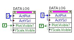
I did it using the graphics property ActPlot, ActYscl and PlotVisble nodes, but I had to for this
through each ActPlot/ActYscl. There are therefore several knots of property in all directions as
in the figure below.
My questions are the following:
1. a lot of knots of property would require more memory or CPU resources?
I do a lot of similar manipulation on the graphics property (cursors, scale, color, etc.). I'm worried
the end result is a program that really doesn't do much, but a lot of memory/CPU hog resources.
2. is there a better way to do it? Perhaps a property node that turns off all
visible at once?
I read in another post that suggests to use a loop to turn off one by one. I can
certainly do it, but it would be a better way?
Any suggestion or the part of the thought is appreciated!
Thank you
CC
Certainly you must change the data that you pass to the chart, especially when working with lots of data. Simple reason: memory usage.
Visibility of switching does not reduce the amount of data that you pass to the curve (that copy for display) as a result, you'll probably lose a lot of memory.
But if you want to display all data at once and only give the possibility to hide the small amounts of data, the approach with the 'visible' property node is OK, but...
hope this helps,
Norbert
EDIT: If you want to change multiple properties at the same time, you must include a control panel (Control Panel-property) defer updates.
-
How to use mesh to 3D image optimization
Hello world
I'm trying to draw a 2d object in a 3D picture control.
The 2d object is a type of polar trace data, contour is variable depending on the data set. I want to display in the control of the 3D image, always in 2D. In my view, that the mesh is the solution. But I can't draw anything in the control of the 3D image. Can anyone produce a small example to show how to draw a polygon mesh into a 3D picture control, where I assume that the points on the polygon can be any number.
I am very new to 3D in Labview picture controls, never needed before. But I managed to produce a nice 3D environment in the control of the 3D image, just stuck on that one aspect.
Any help is always welcomed and thanks for your time to support this amazing forum!
James
Attached, is an example that I put in place. Nothing is not clear or if you want more explanation, let me know and I'll do my best
Jeff Peters
LabVIEW R & D.
-
Hi all
I know it's important to look for answers before posting and I spent several hours to do. I found a few related messages, but the solutions did not resolve my problem.
I have a J2ME application that is fully tested for the game. It works fine when it is installed as a pair of jad/jar on each Simulator and device I've tried. And the midlet icon appears in the interface of the phone, just as it should.
The game uses no RIM specific libraries or modules. As a jad/jar pair, the same build runs on dozens of non-blackberry devices. The code in the jar detects that the phone is a blackberry using System properties and the game is its own minor configuration to look nice on a blackberry.
The next step is to convert the application into a cod file and sign it.
You use the JDE 6.0, I made a new project, imported the jad/jar and run the Build command. The cod was created, and accordingly modified jad. So far so good.
I have my signature identification information, and once again, using the JDE, I ran request Signatures. The interface reported success. No problems.
The cod file is 207 k and consists of 4 cod files. I read the instructions for this case and unpacked the cod file in its 4 cod files. App.COD, 1.cod - app, app - 2.cod, app3.cod.
I've posted four cod files as well as the jad file on my server, the server apache even where I serve regularly jar/jad files.
I have triple checked the mime types in the .httaccess file. Mime types are correct for jar, jad and cod.
I point the browser on the Blackberry 6.0.0.337 Simulator 9800 to the jad file. I get the download window with the properties of jad and the download button. I click Download. If I do this a second time, I get the button replace, so the Simulator think that the file has been downloaded, in this case.
It seems that the files are for download. The watch cursor appears 4 times, probably once for each file in cod. No errors.
At the end of the download, I get a message "the application has been installed successfully" and an OK button. But, no run button, as I get with the installation of the pot. I click OK.
I exit the browser and return to the main screen. There is no download folder. The game is not in the folder games or Applications. If I go to Options/Applications, the game is not listed there.
If I menu click the Options/Applications window, I get: JVM 104 Eception NullPointerException error. However, I had not yet tried to run the application. A stack trace turned up a few odd lines:
UI - EUI no face is detected
VM - BORK
However, I do not know what generated those lines or when.By the way, I also tried to download the full 207 k cod or in this case, I get the 907 error expected because the jad file is referencing files of cod that the server could not find as separate files.
I also tried to download other simulators, for example 5.0.0.54 5 9700. As above, the files seem to download very well and I get the message: "the application has been installed successfully" and an OK button. On this Simulator, there is a download folder, but it is empty. The game is not in games or in the Applications folder.
On this Simulator, I go in the Options/Applications, and there is an entry for my game. The title of the game is OK, but there is no icon. I opened the entry and get title properties and a delete button. There is no run button. It shows the installed date and another button for the properties of the Module. It also shows the size correctly and the signatory IDs.
I also tried this procedure on a physical device, the AT & T 8300. I had the same behavior as the 9700 Simulator. Again, there is no problem with installation of the jad/jar. The problem is with the jad/cod/COD-1/cod-2/COD-3
Why is - this game appearing to successfully download and install successfully but apparently not be installed can thus be run?
Thank you for your time.
Alan WeilerI think I found the problem. I skipped a step during the cod using a jar of J2ME as a source of files.
In the project
 roperties:Application panel, I do not enter the name of my main class name of the Midlet main class field. Apparently this area causes the main class to be the entry point.
With the class entered into this field and re - build the cod file and new signing, I was able to download and run the game on a device.
-
SourceRectAtTime (keyTime, false) does not update?
It is a pretty basic question. I have 1 layer of text to which I added 2 keyframes on the scale property. I need to record its width and its height at each key index. The text of point (although eventually I'll have to find a way to do it with the box / allocated text as well).
So I have
if (layer.property("Scale").isTimeVarying){
     for (var i = 1; i <= layer.property("Scale").numKeys; i++){
          alert(layer.sourceRectAtTime(layer.property("Scale").keyTime(i), false).width);
     }
}
unless I'm missing something, if I turned the scale of the layer between keyframes, I should get different values in my alerts, but I do not have. Am I misunderstood something on the operation of the sourceRectAtTime or is - something unique for text layers, or...?
The result is always expressed in the coordinate system of the layer (text). It is independent of the scale and other parameters of transformation.
If you need to get the result expressed as a model system, you will need to find your way.
In CC2014 and later there is this method useful: myLayer.sourcePointToComp (position_of_some_point_in_layer_system) which gives the result immediately.
Xavier
-
HP Blackbird 002-01 b LED wiring
There are a few wires inside the chassis which look like they are going to LED lighting (they are black and white). There is one single white male connector with a female hooked up with graphics that say "PWR SW + /" there are a few other loose females black connectors hanging graphics saying unrelated "HDD LED + / ', ' RES SW + / ', ' PWR LED +", "PWR LED -" and a white connector. Should be plugged in anywhere?
Under the access panel right side to the top of the chassis, there are Board of directors where there is a similar connector plugged. A connector is plugged into a connector pins 2 and below is another 2 pins disconnected.
Any help or wiring connections photos would be appreciated.
Thank you!
id355 wrote: there are a few wires inside the chassis which look like they are going to LED lighting (they are black and white). There is one single white male connector with a female hooked up with graphics that say "PWR SW + /" there are a few other loose females black connectors hanging graphics saying unrelated "HDD LED + / ', ' RES SW + / ', ' PWR LED +", "PWR LED -" and a white connector. Should be plugged in anywhere?
Hello id355, the son you mention are normally connected to the motherboard in the lower right of the motherboard. You should find the very small pins sticking up from the motherboard with the appropriate labels on the motherboard for each pin.
These are that the motherboard and, therefore before control cables, control system.
The led "disk" is the connector for the activity of the hard drive Led on the front of the case.
The "RES" SW is the connector for the reset button located on the front of the case.
The "PWR" led is the connector for the power on led on the front of the case.
The largest other connector is usually the speaker connector. She usually can accept up to four sons, but most often only has two, the ends of the connector.
The label "+/-" indicates the polarity connectors. Since the connectors can be inserted in the pins on the motherboard or orientation, if they are connected with the incorrect polarity, the LED will not turn on.
Even if the polarity is connected incorrectly, the power switch and the reset will work. If the HDD and PWR connectors are defined in the inversion of polarity, just turn the connectors around 180 degrees and they light up should work.
I have to admit that I don't know where not able to find an example of the motherboard of your system, but here is a link to a motherboard that has been reported as being installed in your model .
You can see the small blue, red, orange connectors on this forum in the very low to the left of the screen.
As I mentioned earlier, since I am not familiar with your system, I can't verify that this information is correct, however, if your system has a standard motherboard, and that these cables are not connected correctly, the system does not boot.
Sorry to be so long and hope this helps.
-
When I transform a raster (png) image, a smaller size it keeps the original resolution?
I'll describe my basic setting to help answer the question.
(1) I am the conception of a corrugated litho label. The work plan of size is size 1:1 to the size of print box.
(2) chart most East of vectors. No problem.
(3) some graphics are rendered png of the product. Here are the rentals makes high resolution (600 / 1200 dpi).
(4) when I add in the file in illustrator, they are size superior, they should be. If I simply turn the scale to 50% is the resolution of the raster image remain the same?
Transforming the image in Illustrator does not change the amount of pixels in the original image.
You must
- Find out from your printer what resolution they recommend. Although the label for corrugated will be 300 dpi or less, usually 2 x lip.
- Open your image in Photoshop. Unchecek resample, change your dpi to your porinter say you.
- Save your image
Now when you place it in Illustrator you will get a maximum quality of your image if you do not evolve, or reduce the image. If you need to put the bigger picture, then you will need to return to a higher resolution. Don't worry about the scale of a small amount of 10% or less, but something bigger that you can Sam art see pixellation.
-
I need assistance with the follow-up of

OK the video you can see on my youtube is that I need help. The video is actually in 1080 p and I don't know why, it's show in such a low resolution, but this isn't the problem. I need follow the gun and add value null to this track, after that, I want to add a red solid layer and bring back some of its opacity to simulate a laser gun sight. Then I tried to parent and SHIFT red solid to the track, the final product should look like what you see in the image. I saw a TON of videos on the follow-up and can not the result I need. the laser must follow gun I aim toward the top and bring the gun to fire. How can I do that..? Please someone help or link me a tutorial that you will find useful...
You must follow two points on the gun, a front and a back if you get angle, scale, and rotation. Apply to null, then parent to your beam.
It is so small and the background is so similar to the firearm that track will be difficult.
-
Photoshop menus on screen high resolution like Lenovo YOGA Pro
I wanted to buy the new Lenovo high-resolution YOGA Pro2 13 ", which has close to Ultra high resolution. I am a user of cc of Photoshop and heard of other menus
are too small to be read. FYI, my daughter has the Microsoft Surface Pro, which has only 1080 resolution and IT cannot read the menus. At upcoming Adobe
a solution yet? Apparently this isn't a big problem with Lightroom, just that Photoshop is the old workhorse and I guess Adobe is happy to accept complaints rather
but to rethink software.
Help?
Install update Photoshop 20141, then turn the scale of IU 200% in the preferences.
-
The size of the edge Web content ID inner frame Animation
I feel like a complete newbie here, but I have questions about two things that I knew very little: Animations of edge and HTML.
I've created an Animation of edge with a specific, smaller than the iPad dimensions step size.
I have registered and used the HTML path to add content to a superposition of Folio.
Animation on Board has been inserted in the chassis, but there was a huge space on the right and at the bottom of the stage space when you preview on the iPad.
I opened the HTML file to try to change the size, but I could not find anything with dimensions.
The scene of edge should be not the size of the HTML frame?
Finally, I turned the scale of content to the size option, and it doesn't seem to change anything in the view. What should I look for.
Please excuse ignorance I expect.
The Animation of the edge is 595 x 256.
I wanted that it sat well in the middle of the largest page DPS.
The problem was that there is a white area outside the area of animation. And if I don't position the frame in the right position, the superposition of web show that white area. (I know that this does not have too much sense.)
However, I discover the background Transparent setting in the Web content settings.
That solved my problem.


Maybe you are looking for
-
Re: NB305 - would be new OS site amenities guaranteed cancelled?
If I reinstall my netbook Toshiba NB305 with Windows XP Professional, it will cancel the mandate he is still underway.
-
HP dv6 ENVY: My Envy of HP dv6 wifi does not work all of a sudden
Hi, I received my laptop 2 years in 2013. He works very well with the occasional wifi disconnects, but above all, it reconnects immediately after. However, earlier I was Surrfing the net, my wifi suddenly disconnected and now it says it is unavailabl
-
Dell Inspiron 15 type jack and audio jack?
Hello I use Dell Inspiron 3542-4627, and I'm about to buy a new helmet. Since my laptop has a single input for microphone and headphone jack, and most of the helmets separated inputs microphone and headphones, I really need to know what type of audio
-
I need to change the card mother fo XW9400. I need to change the OS for this reason. I want to achieve this through HP authorized service provider. What is the number of part of HP for Windows7 Professional 64-bit
-
I have an obligation to provide wireless access to a device group. IPhones/netbooks etc. I have an ADSL wired connection and an AIR-AP-1231. I've connected the AIR-AP-1231 to the ADSL router and have obtained an IP address and got on the management p