Potentiometer digital i2C
Hi all
I am trying to install a simple VI on a myRIO-1900 to use a digital potentiometer as a variable resistance. I carefully used a SPI dpot successfully, but I have problems during the transition to a controlled i2C dpot.
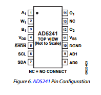
The rest of the data sheet available here ( http://www.analog.com/media/en/technical-documentation/data-sheets/AD5241_5242.pdf ), I made the following connections.
My assumption was a table 1 d of two elements, the first being the byte of the instruction and the second data byte. However, that's just my guess; If you need more information, I could ask the manufacturers of the AD5242 for more information.
Tags: NI Hardware
Similar Questions
-
How to program using Labview to an accelerometer
Hello:
I got an accelerometer which has digital I2C/SPI serial interface, so I bought a USB - I2C converter for data acquisition. I would like to know if I can use Labview to acquire data of com port and also program for the accelerometer to capture the data of the axis z. I have a box of white myDAQ NOR but SB. says that it is not an appropriate device to acquire before I2C/SPI signals. The datasheet of the accelerometer is in the accessory and the specification of the converter is this link: http://www.robot-electronics.co.uk/htm/usb_iss_tech.htm .
I hope someone can solve the problem for me. It is best to use the software labview for me because most of my project work is based on that.
Best regards
The f
Good and bad news. You have an accelerometer that 'speaks' I2C or USB to I2C converter, so if you connect both of them, you can send 'orders' of your accelerometer easily of LabVIEW by using communication series live that's the good news. The bad news is that it seems that you need to address your accelerometer using calls very low level, a work, I certainly don't want to face! This crys on a 'pilot', a middle piece of equipment that does all the "hard work" to take a high level order ("Please tell me the acceleration") and he translates things your device includes (including the Setup program, records, calendar, packing and unpacking of the bits and bytes, etc.).
Bob Schor
-
Digital waveforms I2C library sync settings
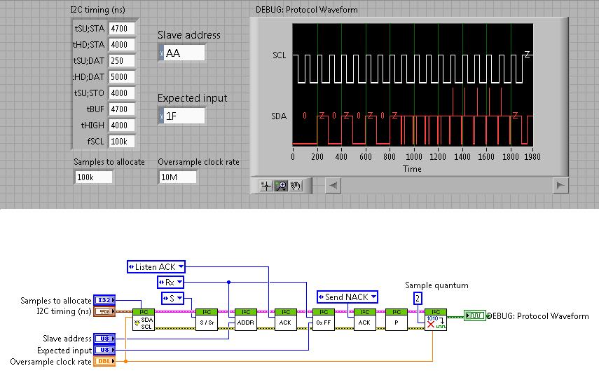
Does anyone know how the consolidation of the 'I2C Timing (ns)' is in the following code? This is an abridged version of the example of the VI "HSDIO I2C - hardware Compare.vi ' downloaded from here. It uses the I2C Digital Waveform reference Libarary.
Time on the x axis doesn't seem to be any help, and the front panel settings are very cryptic in their naming system. No one knows what these numbers mean and how it correlates to real time (dt) between each point?
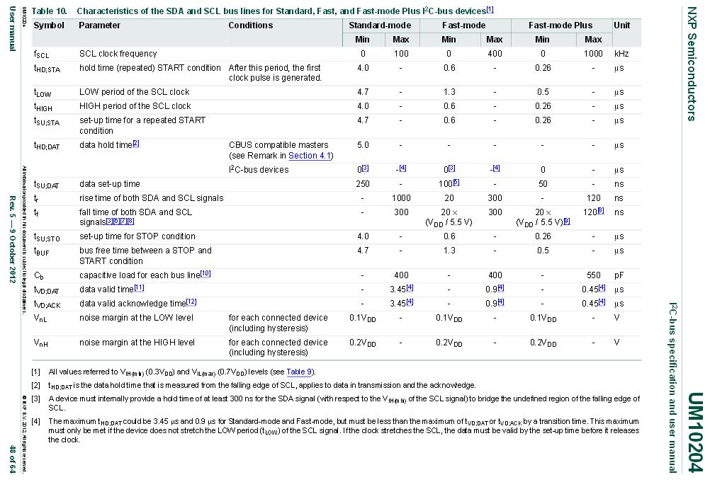
I finally found where the parameters are specified. They can be found in the specification UM10204 I2C - bus and manual.
Under the current revision 5, found in table 10 on page 48:
-
Digital potentiometer through materials
Does anyone have a quick reference to material that contains a digital pot? Is there material that does this? Can you create a digital pot through materials?
Thank you.
Hello Jonathanupr,
I did some research for digital pots we sell and the only one I found was this one. The series 5b on the modules we have created this work on this aircraft back created by Analog devices.
Also, what are you going to use the digital pot for? If you try a current relatively low output voltages, you may want to consider a DAQ with analog outputs on this card. If you are looking for a high current, you can always implement this with a unity gain op amp boost up the power from another source.
-
Why Digital Edge in Trigger.vi start to make some sort of timeout?
Hi I do a manual release on my hardwareboard by inserting a 5 volt source the triggerchannel selected a few seconds after I push the Start button.
The generation ever begins. But if I put the trigger very equal to the sample clock external works listed in annex vi.
For example, I use PFI7 as source of outbreak which is also the source of the sample clock.
Could someone explain to me?
Sincere greetings,
Lasse
We can't simply insert a wire with a 5 V potential to PFI6 for example if PFI6 is used as a trigger for "Start Digital Edge" daqmx - vi. The PIN is floating and inserting just 5V does not guarantee a low aboard high.
If I use a potentiometer to pull on the low channel first, and then increse the tension, the trigging happens.
-
I2c communication and map PXI-6551
Hello
I'd like to communicate with an EEPROM series, so with an I2c Protocol. I have Labview 8.6 and a PXI-6551 card.
Plug-in library I2c pour create communication frames, however I can't seem to send on the 6551, and I must admit that I struggle to understand how the management of the ACK can be done.
If you could give me a helping hand, it would be very kind.
Thanks in advance,
Laurent.
Just to clarify, you will use the HSDIO driver with the 655 x, not the driver DAQmx. Here is a link to the I2C digital waveform reference library, which allows you to build your I2C signals. Then once you have your waveform, here is a link to the document Protocol Serial Communication reference design for digital waveform devices , which explains how to use this waveform with your hardware, and it has a section specifically on the use of devices HSDIO to generate the waveform. These two documents compliment. I hope this helps.
Kind regards
DJ L.
-
8451 I2C simultaneous and IO USB
Hello
I use the USB8451 OR communicate with a BQ77910A of TI by I2C. I2C communication works read at the moment but to write the EEPROM registers that I provide 3.3 v using the IO signals.
I tested the IO and generated a signal successfully. My question is: is it possible to simultaneously run I2C and e/s on the USB8451. They need to be on the same VI in order to exploit?
Thank you
Vid
Hey Vid,
seems reasonable to use two digital lines (what do you mean by "IO"?) and the I2C at the same time. Did you habe problems using both resources at the same time?
In general it makes no difference if you use two resources in a VI or two screws separate
Best regards
Christoph
-
The PCI-6052e does support I2C or SPI communication?
Currently, I am trying to build a data acquisition system to test, among other things, SPI and I2C devices verification of characteristics and surveys of behaviour without advertisement above the different temperatures. The DAQ card that I use is the PCI-6052e as well as the SCB-68. It has 8 ports DIO, but can someone tell me if it will support SPI or I2C? Another post in the forum indicated that it will not support 16-bit SPI, but for my application only 8 bit is necessary. I am not opposed to research in other materials DAQ, such as the USB-8451, but would like to see if the 6052e can do the job first. If she can't, then my next question would be; Can the 6052e and USB-8451 operate in parallel which allows me to use both analog and digital functionality? Thank you
If you will try little he hit then you might find these links useful:
-
I2C implementation using NOR-6008
Hello world
I have a NOR-6008 low cost multifunction data acquisition.
Can I use this with shifter voltage level to apply the I2C Protocol...
You must use the approach of bit - strike (i.e., change you the clock and data lines yourself) and it would be timed by the software. But yes, you could do.
Your next question will be: are there examples? There are many examples on the conduct of IO digital who settle with DAQmx. Regarding the implementation of I2C, the spec is available. http://en.Wikipedia.org/wiki/I%C2%B2C
-
Extract a channel of a digital waveform
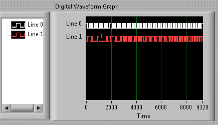
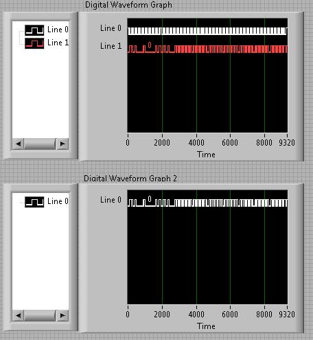
I use the I2C Digital Waveform reference Libarary to create a WDT which consists of two lines/channels. I was wondering how I could extract/remove a channel, the wave form and how can I add/merge signals tracks in a single WDT? I looked around for the screws, but nothing seems to work with the WDT.
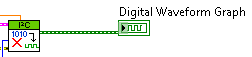
Right now my WDT is like this:
How can I get these two lines in separate WDTs? And then how would I be able to merge them again? Naturally, I don't want to just remove them and merge them, but that would be an example of good practice to demonstrate.
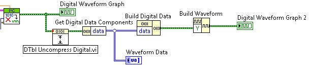
After much trial and frustration, I found a way to do what I was looking for. It is not the most elegant, but it works!
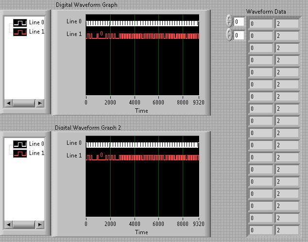
That's how I extracted the two strings in an array and then merge to recreate the original graph:
* Note: The reason why there are 2 in the waveform data table is because my waveform contains 0 and Z instead of 0 and 1. The three States Z corresponds to the 2 digital.
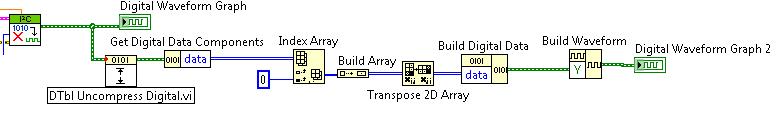
I even took it a little further and extract a single line. This could be changed to extract any line and eventually merge your own custom signals:
-
How can I get the string value displayed on a digital control defined for the relative time.
I have a digital potentiometer to display relative time in increments of 30 minutes.
I want to record the value displayed on the control string. Unfortunately, when I use the "convert to decimal string.vi" number, the resulting string is just the value in seconds.
How can I get the value as a string? (for example 01:30 for an hour and thirty minutes)
Thank you
Sean
Hi Sean.C!
M_Peeker's suggestion is a good thing. A stage that could clarify things is that you must set the % t <%H:%M> format string entry.
 < br / > Kristen:.
 -
Hello
I would like to create a LabVIEW program that communicates to a stand-alone component using I2C.
I guess I'll need to use bitbanging to get this accomplished.
Someone at - it examples of this?
Is it still possible to do using LabVIEW? (You need to somehow quickly pass your line of data between input and output)
Help on this subject would be greatly appreciated!
I've never used myDAQ. If the digital I/o is software programmed as the 6009, no..
-
Any special restrictions on bit I2C port on sbRIO
I know the new Robotics Starter Kit (use sbRIO 9631) and am looking to add some LEGO Mindstorm sensors the robot.
All of them use the serial I2C interfaces.
The sample code FPGA I2C OR uses the bits Port service zero 0,1,2 and 3 to generate two-channel I2C.
My question is: is there something special about these in some ports or bits?
These default port bits are already used for encoders on the RSK entries, so I need to use pieces of another port.
Can take in everything I want, or is it "acceptable" for some songs use.
Docs online anywhere where I should check out?
Thank you.
Phil.
These channels were chosen just for the example. You can use one of the digital lines on board to perform the I2C communication.
-
How can I get digital signals (interface UART) with a microcontroller with NI USB-6008?
I have acauired a few analog signals by A/D (3 channels). I put each scanned data on 3 digital output with a microcontroller. I want to see if it is possible to import these digital outputs 3 to a PC via a USB-6008? It's like the connection of the output to the digital input of the USB-6008 and import the 3 channels simultaneously to LabView? Do I need to use some other hardware like USB-8451 and connect the clock of the MCU to USB-8451?
Saraydin,
The digital I/o on the USB-6008 is a software program only, so unless your signals are rather slow, it probably will not work for you. In general, the procedure would be to connect each signal to one of the digital lines on the map and then set up a digital entry into LabVIEW task to read the three channels. If you use a device that has clocked by the digital i/o hardware, you then your input clock signal and use it as the sample for the task clock. Here is a list of USB devices supporting DIO clocked by the hardware. Also, there is an example that comes with LabVIEW, which shows how to do this. You can get to it in LabVIEW by going to help > find examples. When the example Finder window opens, navigate to hardware input and output > DAQmx > digital measures > Cont read dig Chan-Ext Clk.vi.
The 8451 is specifically for I2C and SPI, and would be great if you try to make one of these protocols, but otherwise I would recommend the devices in the list I linked above.
-Christina
-
I get no picture on the TV when using mini ipad with the Digital AV adapter.
I get a white on my TV screen when I connect my mini ipad digital AV adapter except HDMI 1 showing in the upper left corner of the TV screen. My mini2 ipad works great with the same son and TV. I tried two ipads with different TV but get the same result. The ipad mini works OK if not connected to the TV. Two minis are working on the same operating system setting.
The Digital AV adapter can be finnicky.
Have you tried simply unplug and plug the adapter with the HDMI cable connected with it?
With the adapter always plugged into your iPad, have you tried a hard reset of your iPad by pressing the sleep/wake and Home buttons simultaneously until your iPad goes to the dark and restarts with the Apple logo, then release them buttons?
Good luck!
Maybe you are looking for
-
"Non-system disk" - Satellite 4100XCDT
I recently acquired an old Toshiba Satellite 4100XCDDT. When I turn it on, it says: "Non-system disk"."Replace the disk and then press a button any." I know that the HARD drive has been formatted and he lost the operating system on it. I tried to ins
-
How can I get all my purchases from iTunes on my device?
Some songs I purchased on iTunes is not appearing in my shopping how to do all of my purchases on my computer?
-
Disable the status options of calling on Samsung Galaxy S II
Whenever I log a call with someone, it shows the status of the call directly on the screen and I'm not able to see their faces. I tried all the options and I can't turn it off. Help!
-
Dual Core with 2 separate processors in a Satellite A100-599! ??
Hello My Satellite A100-599 is a Core 2 Duo T7100 2 .00GHz. In the Manager of peripheral devices, processors, I have 2 CPUs: Intel Core 2 CPU T5500 @ 1.66 GHZIntel Core 2 CPU T7200 @ 2.00GHZ Is this normal? I wouldn't not two seek T7200 @ 2.00GHZ? Th
-
Deskjet F2210 printer: Compatible printer driver
Hello everyone I had a question recently bought a Microsoft Surface RT Tablet and I was looking for compatible drivers for my printer HP Deskjet F2210 ios it such a driver available for download.