Analog input USB-6009 pegged about 300mV
I have an USB-6009 data acquisition module. I'm reading a (LM35)temperature sensor voltage. The sensor has three sons: one for the power, ground and one for the output signal. The output is in the range from-1 to 1 V. I have set up the 6009 for entry of CSR in this power range. I turn on the sensor with + 5 volts and ground and measure the output signal using a multimeter (a wire to the Earth, the other to the output of the sensor). Measures with the multimeter check the sensor works (output is environ.2 V indicating the temperature about 20 degrees C).
Then I set the output of the sensor to AI0 and fix the sensor on the 6009 GND ground. As soon as I do, the output voltage of the sensor passes approximately 0,3 v. I check this voltage with multimeter.
I tried several channels to HAVE two different data acquisition modules and several temperature sensors. The behavior is always the same (pegged at 0.3 V voltage).
Any ideas what might be happening here? Do I need to be concerned with the adaptation of impedance for this type of installation? Thanks in advance.
I now have this job. I have used CSR, connected the sensor Vout to AI0 +, connected to AI0 + to ground through a 1.5 k resistor. V connected + sensor for external power supply (12V). Connected to the ground on the sensor on the ground on data acquisition. I have no idea why it works, but the other solutions posted are not. As long as it works, I have no complaints.
Tags: NI Hardware
Similar Questions
-
inputs and outputs analog digital usb 6009
I'm having a problem with my USB 6009 in labview programming. I try to read continuously from the analog inputs while having an event focused on digital output within the same program/vi. Basically, I need to taste all the time the analog inputs while having an event defined by the user (button control) to signal the digital inputs to turn on then after awhile. The event of digital output must be independent of the analog sampling system. I was throwing the "error already allocated resource" in most of the vi, I wrote to try to achieve. What is programmatically possible with usb 6009? I am at my wits end trying to do this and any help would be greatly appreciated (by myself and my boss). Thanks in advance for your answers.
RJ
-
Problem of analog sinusoidal input USB-6009
Hello
I am a newbie to Labview. I'm using Labview 2009 and USB-6009. I tried to use USB-6009 to display the input sinewave of function generator signal. First of all, the perfect sinusoidal looking at the frequency of 1 kHz, but when I changed the frequency of 10 kHz, the sinusoid turned into a triangle wave. When I test the input signal, I put the 48 kHz sampling and Terminal configuration is CSR. Is there a problem with USB-6009?
You really need to spend some time to study sampling and Nyquist theorem-not LabVIEW. To faithfully reproduce the shape of the sine wave, you must go to a sampling rate 10 times higher than your input frequency. With the 6009, i.e. limit the entry less than 5 kHz.
-
Output analog, the USB-6009 case - can I use DAQmxWriteAnalogScalarF64?
I just got a NI USB-6009 and I try to use the outputs analog simple.
I'm running on a Mac, so I'll try to use the API OR-DAQmx Base 3.2 C (downloaded from here: http://joule.ni.com/nidu/cds/view/p/id/1078/lang/en). This is the most recent version of NOR-DAQmxBase, I could find.
I try to do continuous analog output on the 6009, which does not have a built-in clock. I was hoping to do the sync software and just new output values when I want to.
I can't get an output of database to work. Other messages and the example of Windows files, (e.g., National Instruments/NOR-DAQmx Base/examples/ao/MultVoltUpates-SWTimed.c) it seems that the best thing to do would be to use the DAQmxWriteAnalogScalarF64 function.
However, this is not in the Mac version of the C API of NIDAQmxBase. There is actually an entry for this in the NIDAQmxBase.h file, but it is commented out. Anyone know why? Is it possible to use this function for the analog output on request on Mac?
Thank you.
Clement
I have NEITHER-DAQmx Base installed 3.2 on a 10.4.11 system. One of the examples files 'genVoltage.c' calls DAQmxBaseWriteAnalogF64. I was able to compile and run this example with a USB-6009.
The DAQmxBaseWriteAnalogF64 function would work for you?
My guess is that, since you can write a scalar value with DAQmxBaseWriteAnalogF64, DAQmxBaseWriteAnalogScalarF64 becomes superfluous. The example provided with the installation shows how to write a unique value (i.e. scalar.). I pasted the code of OR below.
int main (int argc, char * argv [])
{
Task settings
Int32 error = 0;
TaskHandle taskHandle = 0;
char errBuff [2048] = {'\0'};
Channel settings
Char [] = "Dev1/ao0" chan
float64 min = 0.0;
float64 max = 5.0;
Sync settings
uInt64 samplesPerChan = 1;
Writing data parameters
float64 data = 3.25;
pointsWritten of Int32;
float64 timeout = 10.0;
DAQmxErrChk (DAQmxBaseCreateTask("",&taskHandle));
DAQmxErrChk (DAQmxBaseCreateAOVoltageChan(taskHandle,chan,"",min,max,DAQmx_Val_Volts,));
DAQmxErrChk (DAQmxBaseStartTask (taskHandle));
DAQmxErrChk (DAQmxBaseWriteAnalogF64(taskHandle,samplesPerChan,0,timeout,DAQmx_Val_GroupByChannel,&data,&pointsWritten,));
Error:
If (DAQmxFailed (error))
DAQmxBaseGetExtendedErrorInfo (errBuff, 2048);
If (taskHandle! = 0) {}
DAQmxBaseStopTask (taskHandle);
DAQmxBaseClearTask (taskHandle);
}
If (DAQmxFailed (error))
printf ("error in DAQmxBase: %s\n",errBuff); ")
return 0;
}
Hope this helps!
-
Question of the digital input USB-6009
Hello
I use USB-6009. I have problem in Input.I digital did not connect anything on all channels. But all of the DI/O channels generate 5 volts. And I tested the DI/operating system in the Test Panel also. All digital inputs are high. How I use it? Please suggest me the solution.
You're the one who said it was generating 5V. And I said that a fine should be detected as a logic one. Connect a gnd input.
When it starts, all of the default value of I/O at the entrances.
-
About precision of analog input of acquisition of data USB-6009
Hello
I have a problem where I'm reading a temperature signal (10mV / ° c) using the USB-6009 case, but a problem of accuracy of the input signal of the DAQ hardware. The temperature at room temperature reads at a constant 230mV (23degC) using a multimeter device, but with the DAQ hardware, I see the signal bouncing around to 25mV, + effects greatly my work.
I was hoping someone might have a solution to this as my brief search forums nothing have mounted. Is there a way to average this broad band to the extent of the input signal or from resovle anyway?
Hi mdzz,
What development environment do you use?
Here is an example of LabVIEW that should do what you need.
-
Digital and analog inputs simultaneously - NI USB-6009 and NI USB-6212 - ANSI C
Hello
I'm reading at all times and at the same time analog and digital inputs. Digital and analog samples must be sampled at the same clock and acquisition should be started (triggered?) at the same time (I don't want, after some time, analog reception more digital samples - the opposite is also true).
I found an example (in C source code) "National Instruments\NI-DAQ\Examples\DAQmx ANSI C\Synchronization\Multi-Function\ContAI-Read dig Chan" and tried to run with two USB cards: NI USB-6009 and NI USB-6212. Unfortunately, the two results by mistake, as described below:
DAQmx error: the requested value is not supported for this property value.
Property: DAQmx_SampTimingType
You asked: DAQmx_Val_SampClk
You can select: DAQmx_Val_OnDemandTask name: _unnamedTask<1>
State code:-200077
End of the program, press the Enter key to exit-Is it possible sync analog and digital acquisition in the paintings?
-If so, how?
Thank you
Hello tcbusatta,
Two of these modules, USB = 6008 and USB-6212, support only timed software inputs and digital outputs. This means that you cannot define material timing (like finished sampling or continuous) for these modules. Digital lines can be retrieved or written once to each call DAQmx read.
This means that you will not be able to get any type of synchronization tight between the analogue and digital channels. You will need a Board such as the NI USB-6341 in order to synchronize the AI and DI closely.
-
With the NI USB-6009 analog input lag
Hello
I try to acquire analog signals with NI USB 6009 using LabVIEW. (The signal is 50 Hz of the functional generator).
However, the acquired singnal has dynamic splitters, which is NOT observed by my oscilloscope.
I have no idea why this phase shift occurs.
Any information is welcome. Thank you for reading.
An image file will not help. Post your real VI. If Firefox does not work, use explore or Chrome to fix your VI (s)!
You have here a Subvi, I don't see what's inside and how it is configured. In addition, this while loop is ridiculous: there is no button to stop him running. Never use the red button to abandon for a normal shutdown of a VI!
Why you have configured NChan NSample? Measure a unique signal, Yes? For example, use 1 channel only.
Edit: why do not you play first with an example given, delivered with LabVIEW?
Your LabVIEW, go to the Help menu--> find--> material and output examples--> DAQmx--> entry--> and open 'Input.VI - constant tension!
This VI allows to enjoy your analog signal.
-
Using the DAQ USB-6009 meter and an analog input voltage at the same time.
Hello
Currently, I'm reading the two channels of voltage with the USB-6009. It happens that one of the channels is the output of a digital coder, and it would be much easier to use it directly to the PFIO entry that is defined as a counter. The problem I am facing right now, it's that I can't use the DAQ Assistant to use the analog voltage to a channel and the digital channel counter at the same time. Once I put the DAQ Assistant to read the input from analogue voltage, I won't be able to add analog inputs. And as I put the DAQ Assistant to use the PFIO as a counter, I can add more entries to read analog voltage is.
I wonder if it is possible to solve this problem using the lower level data blocks? Another solution would be to read two channels in analog input voltage and that the use of Matlab to process data resulting from it, since I was not able to do the counting to work simultaneously with the acquisition in Labview to impulses.
Hope you guys can help out me.
Thanks in advance.
Using a simple wizard of DAQ is incorrect. You need one to acquire analog inputs and one for the meter.
-
Hello
I use several USB 6009 units and with some of them seems to have some lag in differential mode, I with 0 to 1V range. Grounded the two terminals with resistors as shown in the tutorial OR «wiring field and noise review...» "seems to fix the problem for some of them, but for those that I have not the slightest compensation first, the ground gives me offset. Can someone please suggest?
Thank you
DS
DS,
Please submit your question in the Forums of NOR. Are you trying to take a differential measurement? What features are you try to measure it and what channels the drop-resistance work with and what channels do they not work with?
-
analog input on USB-6009 - what potentiometer to use for this test?
Hello, I am referring to this video
http://www.YouTube.com/watch?v=rSNRG_Ddl1s
What is the resistance (ohm) the potentiometer used in the film?
Thank you
Luke
They know the author of video ...
Since it is connected to the output of 5V to the DAQ card, you don't want to use too low of a low value.
A pot more of 500 ohm must work safely. Exact value is not critical for this demonstration. Rear wiper terminal must be connected to the analog input, the other two legs go 5Vout and GND.
-AK2DM
-
USB-6009 software simultaneous timed output analog
Ladies and gentlemen,
I worked on a LabVIEW interface to a potentiostat I designed and built. I'm not very experienced with LabVIEW, but do they have experience with a variety of other languages (I had originally intend to use an FPGA for this, but he has been asked to write a LabVIEW VI first) programming.
The goal:
I want to output a voltage (initially consisting of ramps) signal and measure the voltage with an operational amplifier configured as an ammeter of feedback (using resistance feedback and voltage value to calculate current) connected to an electrochemical cell. The resistance of feedback is selected by using an automatic selection function (although I wrote a version prior to manual control) as TTL values using the DAQ Assistant to select relevant MUX channel outputs. I then try to save the data in a spreadsheet.
The problem:
I use an acquisition of data USB-6009, and I know that there is a hardware clock. Read all about him seemed obvious, the best way to the waveform of the output voltage used DAQmx package to define a function of writing in a loop that is clocked by the software. The problem I have is that I can't synchronize the output to the input with reliability and I have also some errors related to resources DAQ being reserved (error 50103). I think the way to solve this would be to convert every equivalent DAQmx DAQ Assistant and try to group their execution - this is where I fall. I tried to write a simple VI who shared a loop clocked by the software to read and write but had problems related to the value of min HAVE (error 200077).
General issues:
How I begin the process of read/write (with a Boolean switch) is very weak and doesn't feel not robust. Ideally, I would like to some form of indicator to warn the user when the read/write process is running and when it ended.
My error handling is terrible, but I find no big thing to read about the basics.
I use only a sequence of no and I think I should have more.
Once I hit the beginning, VI requires the file name for the worksheet - at first, I was afraid that data would be entered correctly, but I think it's okay because the file is generated and then changed. It would be better if the user asked for the name of the file once completed the data collection.
Any suggestion or help would be greatly appreciated. Thank you in advance.
Sincere greetings,
Julius
The hardware supports timed 6009 entry analog. Even with the 1Samp mode, your code could be simplified with a single task and several channels (dev1\ai0:1). Then use Nchan 1Samp.
-
6009 outputs digital and analog input synchronization
Hello
I work in a program NI 6009. I want to leds by car with outputs digital NI 6009. For example, leads first will be on until what 200 micro seconds then second led will be on up to 200 micro seconds, and then first of all led will be on up to 200 micro seconds. I'll take led with photodedector signals and connect analog output photodedector input NI 6009. I want to synchronize the outputs digital and analog input and separate the first and second led signals the analog input for NI 6009 channel. How can you do with NI 6009? Please ADV
You can not do with the USB-6009 case. Its outputs digital are software with a maximum speed of slightly more than 100 samples per second. The outputs can produce 200 microsecond pulses and cannot be synchronized with the analog input.
You need a device with outputs digital hardware timed or counters that can produce a pulse outputs.
You can synchronize a bit digital output and analog input recording signal on an additional channel to HAVE. Will allow you to see the photodetector and LED the drive with the same schedule and such resolution as described by the sampling rate I. The maximum sampling frequency of AI on the USB-6009 case is 48 kHz that is shared by all channels. If you have two lights to led and photodetector two signals maximum sampling rate would be 48 kHz/4 = 6 kHz which is barely fast enough for your 200 US signals. For more than 4 channels, it won't be fast enough.
I suggest a simple oscillator circuit building and use it to clock a flip flop. This will give you alternating signals to drive the LEDs. You can use a line to reset the flip flop to give you control without the need for high speed.
Lynn
-
USB-6212: software problem timed task of analog input
Hi all
I have unexpected behavior using a USB-6212.
The code example shows that when I run in sequence two analog DAQmx to task, material entry first a timed, the second software timed, it happens that the first readings of data are all wrong and have the same value for all channels.
The labour code is the following:
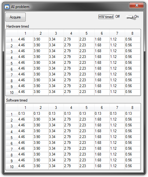
   GetCtrlVal(panelHandle, PANEL_HW, &Switch);

    if (Switch) {
//
// First Task: read 10 rows of values with hardware timing
//
        DAQmxCreateTask("", &htAI);
        DAQmxCreateAIVoltageChan (htAI, MX_DEV_AI, "", DAQmx_Val_NRSE, -10.0, 10.0, DAQmx_Val_Volts, "");
        DAQmxCfgSampClkTiming(htAI,"", SAMPLE_RATE, DAQmx_Val_Rising, DAQmx_Val_ContSamps, 1000);
        DAQmxRegisterEveryNSamplesEvent (htAI, DAQmx_Val_Acquired_Into_Buffer, SAMPLE_RATE, 0, RefreshCB, NULL);
        DAQmxStartTask(htAI);
            Delay(1.0);

        DAQmxStopTask(htAI);
        DAQmxClearTask(htAI);
    }
//
// Second Task:read 10 rows of values with software timing
//
    DAQmxCreateTask("", &htAI);
        DAQmxCreateAIVoltageChan(htAI, MX_DEV_AI, "", DAQmx_Val_NRSE, -10.0, 10.0, DAQmx_Val_Volts, "");
        DAQmxStartTask(htAI);

    for (i=1; i<=10; i++) {
        DAQmxReadAnalogF64(htAI, 1.0, 10.0, DAQmx_Val_GroupByChannel, AcqVoltRow, HW_AI_CHANNELS, &read, 0);
        SetTableCellRangeVals (panelHandle,PANEL_SOFT, MakeRect(i, 1, 1, HW_AI_CHANNELS), AcqVoltRow, VAL_ROW_MAJOR);
        Delay(0.1);
    }
    DAQmxStopTask(htAI);
    DAQmxClearTask(htAI);
A picture is worth a thousand words: analog inputs have been connected to a network of resistance have known values.
The upper table contains timed material acquisitions, the lower the software timed readings... as you can see it the first line is the set of values of 0.13, totally wrong
If the task of timed acquisition of software runs without the earlier (in my demo, that this can be achieved by the switch at the top right), the readings are correct!
Y at - it something I am doing wrong?
I also tried to run the program on USB-6009, but it seems to work properly.
[LabWindows/CVI 2010 SP1 - driver OR-DAQmx 9.4 - Windows 7 x 64]
This problem was corrected by NOR-DAQmx 9.5
324044 NOR USB-621 x task HAVE request returns incorrect data after erasing a task HAVE stamped
-
What is input equivalent circuit of USB 6009 PFI0
The entry USB-6009 PFI0 is the same the analog input circuit stated in manual mode?
I use the PFI0 to trigger a measurement of voltage and it works a lot using a HP function generator.
When I try to drive the low entrance with my circuit looks like there's a pull up resistance to + 5 on the entry of PFI0 terminal.
This entry PFI0 will accept an output of comparitor from 0 to 15 volts with being damaged?Kip
Here is my solution to operate the PFI0 TTL digital input using a CMOS comparator.
I use a 2N4401 npn transistor.
Connect the transmitter to the ground terminal.
Connect the manifold to the PFI0 (there is a pull-up internal resistance to the 6009).
To connect to the Base of a voltage divider that limits in input current and decreases the CMOS voltage to TTL levels.
In my case I'm going to 0 to + 15 so my voltage divider is 4.7 k and 2.2 kohm to fall to 0-5 volts.
It is an Inverter circuit so your sense of trigger will go head on falling edge, or vice versa.
I hope this helps someone.
Kip
Maybe you are looking for
-
Updated software iOS 9.3.3 and stop receiving notifications of the iPad
I updated my iPad 2 for iOS 9.3.3 and stop receiving notifications or imessages. The do not disturb button is not enabled and the apps are put in place to inform. I reset the network connections on my iPhone and iPad, rebooted several times and reset
-
It is a matter of settings I'm not smart enough to understand. My Safari opens in a partial screen display. How can I get Safari to open in a view in fullscreen? Thank you.
-
How can I find the history of the app on itunes or the app store for my iphone 5? I got an iphone 5s and it broke... now I have another but want to see the history of my old phone apps.
-
"Aggressive Wi - Fi for mobile data transfer" Developer enabled / disables itself off to restart
Hi, I have experienced the behavior in the subject line since the installation of the update of the firmware of Marshmallow. Is it possible to prevent this? Firmware version is 23.5.A.0.575.
-
On startup, I get '0251; System CMOS checksum bad - default configuration used"and I have to reset the date and time. How can I fix this?