5761 PLL at PXI_CLK10
Hello
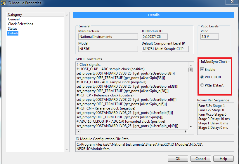
I want PLL select my 5761 to PXI_CLK10 by setting the sample clock signal. I use the adapter with an SMU-7965.
The Manual 5761 synchronization article leads me to believe that I can do this: "Reference, 10 MHz, external clock through IoModSyncClock."
The subject of several CLIP sample 5761 in aid of FlexRIO gives me the value to write, "select the sample clock, 3 = sample clock internal locked to an external reference clock through IoModSyncClock".
And
I'm missing how to get the PXI_CLK10 to IoModSyncClock. There is an explicit note in table 4 of the Manual of 5782 indicating, "the VCO internal locks to PXI_CLK10 through IoModSyncClock, which is available only through the backplane of the SMU-796xR NI devices", when the clock is set to the internal clock PLL on (IoModSyncClock). Perhaps the same applies to the 5761 even if they seem to have different options for overclocking? I don't want cable CLK10_OUT of the chassis at CLK IN on the 5761 (which seems silly). I don't want to use the API of Sync FlexRIO Instrument Development Library to PLL to backplane. Thanks for any help, Steve K You set the IOModSyncClock line in the FAM Propties page on the category details. By default, the PXICLK10 is automatically routed to the IOModSyncClk line. Tags: NI Products Why SPI participates with clock select on 5761/2 scanners? The CLIP reference for the 5761 5762 sample clock commit signal States, and "when going from FALSE to TRUE, updates the sample clock according to the settings defined by the signal of selection sample clock." Shipping examples bookends the rising edge of clock sample commit with SPI Idle check. Why the SPI is involved with setting the sample clock? Thank you Steve K I have a requirement to PLL to IOModSyncClock, so if SPI become inactive within the time limit, should I give up? In other words, if SPI will not idle 10 ms after the rising edge of clock sample commit, so I am not locked (for example clock select = IOModSyncClock lock).
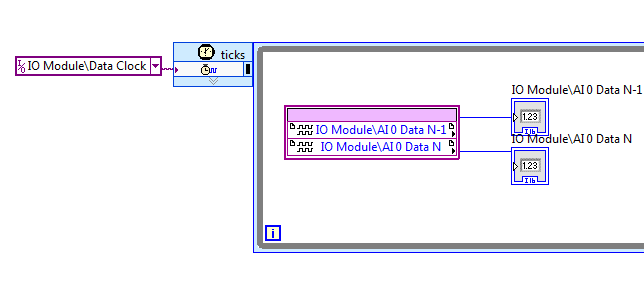
I would not abort, rather I'd throw a significant error that allows to recover gracefully or stop the execution. Otherwise, it seems that you have the correct impression on which should involve the remaining false SPI Idle. However, I think 10ms sounds a bit too short. I'd go with at least 100ms, probably closer to 1 s just to be sure. If it takes more than 1 s, then you can assume that something has not been configured correctly before you start setting the clock. PXI_Clk10 can be found in PXI6115. I have two PXI6115, and I want to sync them. I found an example of examples of NEITHER. He said that both PXI cards can be synced through sharing RefClk10. But I can't found this reference clock signal. Can you give me any suggestions? Thank you very much. Frogreenmm, Let me see if I can help clear up your confusion. First of all, PXI_Clk10 is a signal that is present only in the PXI chassis. PXI-6115 have a PLL to lock to the signal. However, as you said you have a PCI-6115 so this synchronization scheme is not available to you. To synchronize these devices, you must share the signals between devices through an interface. You mentioned that you have a RTSI cable, so it will be the best way to do it. To use RTSI with DAQmx, you will need to go to the measurement and Automation Explorer (MAX) and add RTSI cable as a DAQmx device. This DAQmx allows to know the presence of the RTSI cable and will also allow the driver to perform automatically routes between your devices using this interface. To add cable RTSI, go to MAX and expand devices and control of the Interface. NOR-DAQmx devices and choose create new DAQmx Device-> RTSI cable. The RTSI cable should then appear in your list of devices. Right-click on it and select 'Add the device to RTSI cable.' This is to add both of your PCI - 6115 s RTSI cable. At this point, I guess you have physically connected the two devices with cable and now DAQmx knows in this regard. Now, we could use one of the many methods to synchronize the devices. We can share a master time base and start the détente between the two devices or we could share a clock sampling and a trigger of departure between the two devices. The example of delivery DAQmx titled 'Multi - Device Synch - Analog Input - Finite Acquisition.vi' is an example of how share a time base and trigger start (look at the case of block diagram ' E and S series share Master Timebase '). In this case, the two devices will share the time base of Dev1, and both devices will use the beginning of Dev1 trigger to begin their acquisition. As long as you added your cable RTSI for MAX and added your devices to the RTSI, DAQmx cable can take care of the details of routing of these signals. An important note about this approach is that you call start on the 'slave' (Dev2) 6115 before calling start on the 'master' (Dev1). It is so Dev2 is ready for the trigger start signal when Dev1 sends it. You can use a very similar approach by a sample clock between the two devices sharing rather than share the main time base. Yet once again, I recommend that you also share a trigger to start and start the 'slave' device before starting the "master" unit Hope this helps, Module e/s NI 5761 clock compiled 0 to 100 MHz in single/multiple Sample CLIP examples of projects Hello I was trying to wrap my head around the CLIP sample NI 5761 Multi (v4.1.0) because the CLIP provides 250 PSM data, but the IO module requires a clock of 200 MHz. I think, ' NOR should handle the conversion of the clock, fine, but I hope that the diagram is running at 125 MHz... otherwise I'm really confused "so I look at configuring the clock Module e/s in
I checked the target 7965 in NI 5761 single sample CLIP\NI 5761 - unique CLIP.lvproj and IO Module clock 0 sample was compiled for 100 MHz there as well. I do not understand the difference between the flow of data and the selection of clock 200 MHz IO module, and it would be nice to understand it, but not necessary. Also, I don't understand the difference between data rate and the configuration of the Module e/s 0 clock that drives the SCTL that contains the node IO. I understand that to move forward. Thanks for any help, Steve K The CLK200 in the selections of the clock is used to excite the parts of the fixed logic that are internal to the CLIP. Some CLIPs FlexRIO may only require a CLK40, this one requires a CLK40 and fixed a CLK200 to properly perform its logic. Thus, it seems that everything is ok in regards to that. Unfortunately, the example incorrectly uses IOModClock0. The SCTL AI IO node resides in should use a resource of the clock that says "Data Clock. We've updated the examples in more recent versions of the pilot, but you seem to be using a version of the driver where a CLIP that uses the clock of data is the latest available for the 5761 CLIP, but the example has not yet been udpated to use. How to choose the line PFI to use on the port of the 5761? I understand that the VIDEO that I use on my DAC 5761 allows me to access 8 PFI lines. However, when I access my 5761 devices in the project window by clicking the "+" next to the name of the module, I see that 'PFI Input' and ' output PFI. I tried to get this to send a signal in the past, but I have been unable to determine how to select the line PFI I want to use. How can I select the PFI line? Any ideas? I was able to get the my AWG PFI (5422) for work and it is amazing. I want to order an attenuator digital step for a ground penetration radar that I develop. Your time and your help is very appreciated. PS: I have worked with this PXI system (chassis, embedded controller, FPGA digitizer 5761 and AWG) for 1 year and I am afraid that it is time to learn this one way or another. Good day! -Daniel I found the solution. In addistion to the node which is visible in my previous post, there must be a node to enable PFI write with an entry of decimal number indicating the line is activated. Then, there must be a node PFI active connector, set to true. Not sure if the node of the latter is really necessary, however. Otherwise above examples should work as is. 5603 IF given NOR 5761/a. port Hello I have a composed of digitizer vector signal Analyzer 5622, 5603 frequency step-down converter and synthesizer 5653. To get to the point, I'm trying to synchronize the clocks of the ASB and the 5761. as well as the module of synchronization, Richie Hi Richie, It is possible to generate two different clocks, but you shouldn't need to. The best way to do it would be to spend the clock by Ref Out of 5653 for Clk synthesizer in the digitizer 5761. More information is found in the Starter guide for the SMU-5665. Replace just the 5622 by the 5761. The LO is usually set on a certain signal IF according to the RF input to output. I don't think there is a way to change this, but you can set your scanner to wait for the correct values. Concerning How can I get the CLK OUT using PLL on NI PXI-6652? I'm trying to get out the CLK using internal CLK either or PXI_CLK10_IN and PLL DDS source to the required frequency. In other words, I want the CLK coming OUT the NI PXI-6652 be PLL frequency required. Ashok Hello Unfortunately, it has no direct route in material to get the DDS at PXI_CLK10_IN clock. In general, PLL is used for external signals that are out of phase with the system and not for signals generated internally. From the 665 X operating instructions online, here is an overview of the functions of the Board of Directors: NOR error-89136 property set DAQmx_RefClk_Src with value/PXI1Slot2/PXI_CLK10 Dear members of the forum OR,. We have just received a chassis NI SMU-1073 with an SMU-6361 OR switched in PXI1Slot2 and a shielded connector BNC-2111. Aims to trigger two output signals to control a laser and a sound via Matlab Application. Version of Matlab is 8.2.0.701 (R2013b) and data acquisition toolbox is 3.4. Installed is the 9.8.0 driver NOR-DAQmx. We followed the example of the tutorial on the web page of Matlab to generate output. The code establishes a connection with a device, it creates a session and adds an output channel. Once this is done, the session is started in the foreground, but it fails with the following error massage: OR error-89136: Specified route can not be satisfied, because the hardware does not support. Property: DAQmx_RefClk_Src Requested value: / PXI1Slot2/PXI_CLK10 Based on some forums, we checked the route tab of device in Explorer automation and PXI_CLK10 signal is almost yellow everywhere. Looks like he expects, as a reference, the PXI_CLK10 clock, but there is no direct route to it. On the other hand, there are PXIe_CLK100 that is green. Question is how through Matlab interface based session one can set the reference clock signal? Or y at - it another way to solve this error? Maybe another type of configuration is necessary? Tips, drivers, and solutions are welcome! Thank you in advance! see you soon, go9kata P.S.: the same question has been added three different times to Matlab support page, but there was no response to all the http://www.MathWorks.de/matlabcentral/answers/107494-acquire-synchronized-data-using-PXIe-devices http://www.MathWorks.de/matlabcentral/answers/37134-data-acquisition-from-NI-PXIe-1062Q Hi all the last questions are displayed also here and replied: Modulation Toolkit PLL filter setting Hello I try to use the PLL vi in the Modulation Toolkit to lock to an external frequency acquired a 24 bit data acquisition card. The external FREQ is in the range 30-800 Hz (chopper optics) and the sampling frequency is 20kS at this time. The ext signal is a square wave. Finally, I need to generate a sine wave (only in software) locked on the FREQ of ext. With the default loop filter settings, I cannot get the thing to work properly, means no stable frequency and the BW of the PLL seems to be too high (sin (phase) is trying to follow the square signal if the vco gain is greater than 0.001). I also looked at the example vi "Measures MT Passband PLL". Problem is that I don't have any idea on how to change the loop filterparameters IIR. I checked the Web for some details on the pll, but so far I couldn't understand things. Looks like I need a current depth on control systems... Can someone give me a hint on how to proceed? Do I really need a full cycle of the DSP or can I get away with a few experiences? Thank you Klaus Thank you Bernd, I tried a few filters and now finally done with the default coefficients! It turned out that they work very well for my purpose. However, the default filter for some reason settings any require a signal that passes through 0 (a 0 - 5V TTL will not work!). I now use the vi "scale 1 before I have to send the signal to the processor of the pll. The output nonlinear phase in higher gains can be treated by linearization of phase in a specfic fitting routine. It needs enough oversampling to do. Now I have at least 80 dB suppression of harmonics in my outs (independent on vco gain) pll. To really improve things, a filter PLL vi design would be needed that implements all the theory. Klaus p.s. I found the tutorials on this site very useful: PLL error-1074118135 could not phase-lock of the external reference clock I tried to block the generator of signals Vectoriels PXI-5671 until its source Ref in instead of the clock on board and it is the following error is received: Error 1074118135 has occurred to niRFSG wait until what Settled.vi Possible reasons: The converter has reported the following error: Measurements: PLL could not phase block for external reference clock. Make sure that your reference clock is connected and that it meets the specifications of the voltage and jitter. Additionally, make sure that the reference clock frequency is correctly specified. The clock source I use is the right frequency (10 MHz) and levels (I tried + 6 dBm and + 12 dBm). However, I was never able to get the 5671 to lock to the Ref in the clock source. Any thoughts? I haven't dived in the measure of the quality of the 10 MHz clock source that is fed to the VSG but it comes from a device of precision GPS timing, so I'm optimistic that the quality of the clock is within tolerances of the plug VSG. Hello tsileo, The 5671 requires that you provide it a square of 10 MHz wave which is free race to +/-0.5 ppm precision. I think that the amplitude levels look correct. I would like to confirm the accuracy of your GPS unit's clock. I also would ensure that free running clock is scheduled before the NOR-RFSG task. According to the frame that you use, you might be able to try to connect to the clock of 10 MHz of the chassis with the REF in connector just to make sure that there is not something wrong with the device. Kind regards Paul C. I just added a PXI-6653 to my chassis PXI-1011, in slot 2 and trying to replace the basket bottom 10 MHz native PXI_CLK10 with high precision an OCXO in the 6653. The goal is to provide a divided (by a factor of 2) reference clock, which has the accuracy of the OCXO. I run this in LV 7.1, NOR-MAX 4.5 etc.. The attached vi first connects OCXO to PXI_CLK10_IN, as a replacement for the native clock precisely this one. This part comes from "Clock.vi of road NO - SYNC" Then, from 'NO-SYNC Generate DDS Signal, fracture and Route.vi' DDS takes the exact PXI_CLK10 of backplane and brings it to CLKOUT full frequency, but also a more bass that is divided by a factor of two to the EPR of PFI0. The problem is that when I have the clock frequency to measure CLKOUT, there native backplane clock frequency (lack of precision), or approximately +/-4-5 ppm. I calibrated in fact my meter frequency by porting the OCXO out CLKOUT with the first vi, and it is calibrated to +/-0.5 ppm today. My problem would be with the PXI-1011 chassis compatibility problems? I read in another thread on someone with a PXI-1033, which had put the switch S1. I can't find any S1 or other switches config on this chassis. Someone at - he had similar experiences with the PXI-6653 and former chassis? Thanks in advance for your comments, Kurt Peter, Thanks for having a look at this. Yes, initially I brought OCXO to CLK_OUT, NOR - way Clock.vi SYNC and adjusted using the cal on the K & B (it has only 7-1/2 digit precision) for 10 MHz. This could serve as a basis to determine if I managed to replace the native frame PXI_CLK10 with the more precise OCXO. The fact that the attached vi gives a PXI_CLK10 read only 10,00008 to CLK_OUT MHz gives to think that my chassis is unable to accept the OCXO on the PXI_CLK10_IN line. Referring to the manual for the chassis PXI-1011, under Section 1, 'Reference of system clock', missing the verbiage I should be able to do this. Other chassis, such as the "1000/B, ' 1042 and even the ' 1010 have verbiage that PXI_CLK10_IN line can be operated by an external source." So, I suspect that an upgrade of the chassis is in my future. Thanks again for the reality check! Kurt exec_sql. PLL in the form of 11g Hi all I've struggled for some time with a form of migration problem. Reminder: My business is migrating to Oracle 10 g 11 g form through all the screens, libraries and all objects in general. A few days ago, I found a screen which opens a connection to the database and execute instructions (grant privileges, change password), this form uses exec_sql.pll which is apparently a package included in the implementation of forms since version 6. The problem begins when I took the current exec_sql.pll of my deposit and try to compile in Builder 11g. the main problem is that there is a function that does not compile: PACKAGE currconn BODY IS -This is the definition of package for currConn -For Developer/2000 R 2.x, which makes implementation of the STPROC. HSTDEF -procedure. FUNCTION get_curr_conn RETURN pls_integer IS hstdef PLS_INTEGER; BEGIN stproc.hstdef (hstdef); Obsolete in Forms11g - form of Oracle 11 g Migration connection_id: = EXEC_SQL. DEFAULT_CONNECTION; Tensioner: = EXEC_SQL.IS_CONNECTED; RETURN hstdef; EXCEPTION WHILE OTHERS THEN RETURNS A NULL VALUE. END; END currconn; According to the documentation of oracle forms, this guy here [stproc.hstdef] is now obsolete. Therefore, because that's why I can't continue with the compilation. the logic to connect to the DB and execute some instructions is present across several screens, so ideally, I would like to correct the root cause of which is the library and not apply with a workaround in each single fmb Issue. 1. is there any place where I can download a newer version of exec_sql.pll? 2. If the answer to #1 is NEGATIVE, is there another way to get around the above function? OK, time for me to chime... If you need not STPROC so it is not a problem because it no longer exists. What you need to do, is not to use an old pll. Since functions supported this old pll are now based in the forms, the library of the add-on should no longer be needed and your form should compile. If it is not the case, your form code must be updated correctly. If your concern is that you have a lot of modules should be updated, you can use the JDAPI or CAPI to perform updates all modules quickly. If you do not correct the code at some point, you will continue to have this problem every time you upgrade. What will happen when you need go to v12? Why I can not customize LOV use custom.pll or customize as a Receivables Transaction? Hi all.. I have business to customize LOV form transaction purposes. I try to use custom.pll or customize but I can't do it. I want to Bill of LOV customized for. It is a real request for Bill LOV to. Select cust_acct.account_number account_number, Party_name party.party_name, arp_etax_util.get_taxpayer_masked_value (Party.jgzz_fiscal_code) jgzz_fiscal_code, arp_etax_util.get_taxpayer_masked_value (Party.tax_reference) tax_reference, cust_acct.cust_account_id customer_id, cust_acct.fob_point fob_point, fob_point_meaning null, cust_acct.ship_via ship_via, ship_via_meaning null, cust_acct.primary_salesrep_id primary_salesrep_id, primary_salesrep_name null, primary_salesrep_num null, cust_acct.account_name account_description of hz_cust_accounts cust_acct,. part hz_parties where cust_acct.party_id = party.party_id party_name order I just want to change the label account_description to another name. or I try to add condition where. But same result, I see no change in this LOV. Please help me. Thank you... Can you check this http://kiranyarraalwaysreadytohelp.blogspot.com/2014/03/how-to-restrict-lov-using-oracle-form.html Error in compliling the AXF_Custom.pll Hello while I'm configuration of the EBS with Webcenter adapter I get error at compiling of the file AXF_Custom.pll in Oracle Form Builder Apps Server Machine, below, please suggest. identifier of DBMS. XMLDOM. DOMDOCUMENT must be declared. I'm at the link below to set up the adapter of the EBS. http://docs.Oracle.com/CD/E21764_01/doc.1111/e17953/c02_ebs_plugin.htm#ADTAD153 Thanks in advance Hi all We can follow the alternative to compile the AXF_CUSTOM.pll file. using the command, we can compile the pll file $APPL_TOP/au/12.0.0/resource>frmcmp_batch.sh module = AXF_CUSTOM.pll userid = module_type output_file = AXF_CUSTOM.plx apps/apps library compile_all = special = For more details follow the 2.2.1 AXF_CUSTOM.pll compilation step using the command below document line Thank you Maximum size of Custom.pll/Custom.plx Hi all Could someone tell me if there is no limit of size on custom.pll/custom.plx in EBS. All entries are greatly appreciated. Best regards gt1942 Could someone tell me if there is no limit of size on custom.pll/custom.plx in EBS. No, unless you reach the limit of the file size of your type of system file or at the level of the BONE. Thank you Hussein REGZA LINK RD88TKTB & 32RAV635DB how to make them talk? I just bought HDMI TV 1080 p 32RAV635DB & RD88TKTB HARD drive recorder and they both boast REGZA link. I looked in the manuals and online and can't seem to find how to get them to talk to each other. HDMI cable is connected and display 1080 p mode. F Problem with the ergonomic backlit keyboard. Why Microsoft is not dating an informed ergonomic keyboard? I'm so use a your keyboard 4000 and 7000 I don't want go to flat keyboard straight. Once the lighting of graphic works, I used to want to off thus creating a problem to see the keys. Glue th 6710 Pavilion: A newer card reader will replace the 504857-001 in my Pavilion I need to replace my Pavilion card reader. A new HP card reader will replace my PIN 504857-001, or should I find a 857-001? Room Dell place Pro 8 USB mic? I have a Dell place Pro 8 with a broken micro-USB port. The tablet belongs to my daughter to years of high school. I think she may have plugged in upside down too many times. Dell wants $269 to repair (Exchange motherboard). Anyone know or knows wh Windows 7 Professional, several computers. How many computers is covered by a professional software for windows 7? We need at least 2 computers, 2 of our 4 already have.Similar Questions
Dan
I also a 6674 t connected to an atomic clock synchronization module and a card 5761.
Instead of going directly to the digitizer, I am currently trying foods I / data Q If the buck converter of frequencies at the Ch0 of 5761 card input (A/D)
in order to process the data immediately in the FPGA.
as I am able to get the number correct samples at a certain frequency of sampling to the 5761 entered.
What I need to do to exclude the digitizer and have the 5761 in lieu of the digitizer?
I'm quite new to using NI DAMA and Module synchronization tools in Labview, but I've included the VI I am trying to run on the host side at least for
a Visual idea.
http://docs.Oracle.com/CD/E29542_01/doc.1111/e17953/c02_ebs_plugin.htm#ADTAD1276
Maybe you are looking for