Readings of Multisim Simulation
Heelo everyone,
I am new to electronics and I would be grateful
If someone please help me understand what to expect on the readings of anylyzer
Attaché please. Also I'm not sure if the connection of the circuit is good.
I appreciate your help.
Thanks for looking
Please see my replay to http://forums.ni.com/t5/Circuit-Design-Suite/Simulation-HELP/m-p/3162722/highlight/false#M17650
Tags: NI Software
Similar Questions
-
Multisim simulation of co error
Hello
When you perform a simulation in Labview (using a model of Multisim) in the Loop Simulation & control, sometimes a small window pops up with the error: Multisim is closing due to the error... (or something like that, I don't use multisim in English) even if I did not open at all Multisim. I think that it opens in the background and it closes because of an error.
If someone could help me, I would be very grateful...
Thank you
Ussr123
Hello
I think I already know what the problem was. I was providing some input values in my file of Multisim simulation. These values were floating point numbers, and sometimes with a micro digits after the comma. It seems that Multisim couldn't handle it. After cutting all the numbers they came after the comma, leaving only 2 or 3, the error seemed no more.
I hope I could help, if everyone will head the same error, try to think of cutting the floating numbers to real numbers.
Ussr123.
-
NI Elvis and Multisim interactive without labview
If a circuit is implemented and tested with the help of Elvis, the results of an output displayed in Multisim and Labview? If I want to change my Multisim simulation to match the output of the circuit set up as Elvis, is possible in real time? I know that TINA can do with their hardware/software. Thank you
jweaver-
You can display the measurements in Multisim and LabVIEW. With NI ELVIS, you can use 12 instruments of autonomous software by installing the driver (FGEN, Noculars, DMM, ect). The instruments are built using LabVIEW. You can access these same instruments in Multisim environment and compare the Multisim circuit simulation commensurate with live material in real time. I included a tutorial describing how to do it using equipment OR myDAQ. The steps are the same for NI ELVIS.
If you want to create a custom beyond the 12 instruments application, you can program the instruments in the LabVIEW programming environment.
" Use myDAQ with NI Multisim Circuit Design software
-
Execution of Multisim with Labview
Hey,.
I'm trying to convert a series of laboratories studying for a class of dynamic systems run on a newer, better set up. Previously, the laboratory, I'm working on that took input from a sensor, fed entry through an analog circuit that feeds the output of this circuit a Labview VI. My question is, which is possible by using a Multisim simulation instead of a physical circuit? I found volumes about Labview screws running in Multisim, but nothing about a taking a Multisim circuit inlet VI. If this is possible, what configuration do you suggest?
-
Could not open the instrument LV
Hello
I want to use biomedical in my multisim simulation and following of this document signals. I downloaded the file and copied to the specified folder, but unfortunately I am unable to see in the specified palette.
Kindly tell me how it could be solved.
Thank you
-
I'm currently building 555 timer with 8 bit counter to reset after 180 seconds (3 minutes). and I want to see the waveform of the time count. I made this circuit, but it doesn't seem to help u working.can me to build again and I display the waveform.i use multisim simulation software.thanks
post your circuit diagram
-
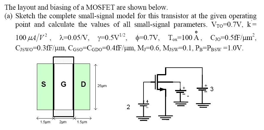
Translate 'Weird' in the calculation of the capacity of MOSFET
Hello world
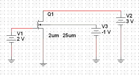
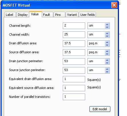
I have a problem with the result of the simulation to calculate N - CH Mosfet capacitance (Cgs, CGD and CBD).
In this simulation, I tried to check my manual calculation with the result of Spice to 11.0 Multsim. But the result in Multism simulation is stopped different from the manual calculation or Pspice/Hspice simulation.
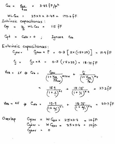
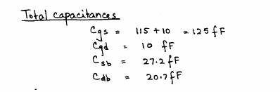
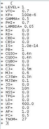
Manual calculation:
Multisim simulation:
Definition of parameters in Multisim:
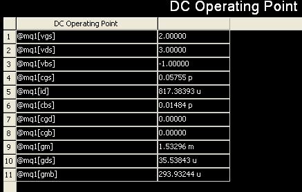
. Multisim DC
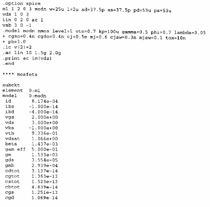
> DC of PSPICE
It appears from these results that Pspice gave a value close to the theoretical calculation of the MOSFET here. And I got the result in Multisim.
Can someone help me solve this problem?... Multisim is not as powerful as other spices software? or simply, I messed up with the Multisim formatting settings and ended up with the wrong answer?
According to me, you go always peripheral the capacitances output variables. These would be only the capabilities reported and identical to the DC - incorrect. We checked the code and capabilities used in the analysis are the right ones.
To illustrate so, using variables real circuit - voltage and current, I calculated the impedance looking in the door to a range of 1 GHz (its a little non-trivial to demonstrate the impedance of specific capabilities because you can't get out easily aware of the capacity). The results are similar to PSpice.
So to reiterate - the real circuit test results are not affected. For now, we ask that you do not watch the variable capacitance device because it is incorrect.
Hope that helps.
-
Multimeter simulation Multisim not showing after reading press simulation
I'm running student multisim version 14. I made a very simple circuit and to place two multimeter and run a scan dc.
But the problem I am experiencing that I'm window calculation but multimeters not show any value of simulation.
can someone help me understand this please.
Hi shabeesatsangi,
The meter components are intended to be used during the interactive simulation. When you run the DC OI analysis, you will see the results in a table in the grapher.
To display the values in your multimeters, change your simulation mode to Interactive and run the simulation.
I hope this helps,
Jeff
National Instruments
-
Hi all
I played a bit with multisim for a few years now, but later began to really use the features of simulation of the program. I noticed that transient analysis of the very basic circuits seem to work fine, but nothing more than (especially those using pwm controls) after bogged down as some ridiculously short period of time. Also, before it freezes, things as the output of the oscilloscope function very slowly. I have attached my circuit for reference and using all that you wonderful people out there. What I am doing wrong?
The wizard of error correction is not really take care of the problem.
FYI, this is a converter circuit high power for which I would like to study the out performance characteristics by changing the frequency of the triangular wave or setting of the amplitude of the sine wave from 0 to 1. The goal is to produce a sinusoidal current output to the primary of the transformer. The resistance of inductance and conductor of leakage have been modelled, as well as an inductive load on the secondary of the transformer.
Thank you!
Yes, I tried for a few days and all the other typical timestep of bugs and it does not always work. The solution was to replace the igbt with the command switches in idealized voltage and barrier diodes schottky antiparallel... and on the ground of the transformer floating seconday. It works now
-
Multisim co-simulation / LabVIEW
Is it possible to add contacts from two States to Multisim and control of Boolean way to LabVIEW?
the attached example schema
-
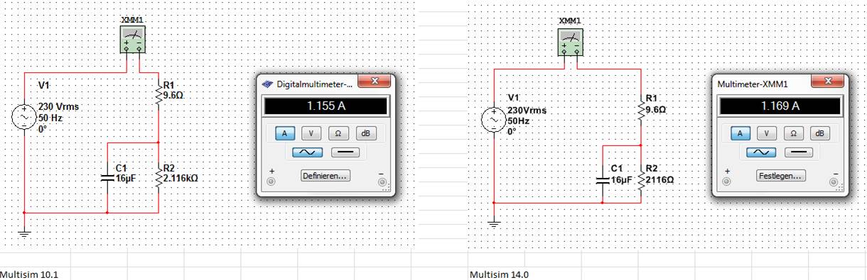
difference of simulation between multisim 10.1 and 14.0
I've been using Multisim 10.1 for check and create examples for students and want to spend 14 Multisim. Simulating a small ac-circuit I got different using multisim 10.1 and 14 results.
The result of multisim 10.1 is identical with the manual solution.
No idea, what could be the problem?
concerning
blanne
Hi Blanne:
The default setting of simulation in Multisim is letting his engine to automatically determine the TMAX, the maximum allowed timestep. In version 13, we have modified this code in such a way that it will leave the slower to simulate faster real-time frequency circuits, we did this in order to accelerate simulations as requested by users. Most of the time, this change has worked as expected, but your circuit is a clear example of a negative effect of this change. Its accuracy is affected by larger time.
In your evaluation of Multisim 14, you can quickly change that. Click on the Interactive analysis button in the toolbar to open the properties of the analysis and in the analysis of Simulation Interactive > look tab crawl settings for the checkbox control labeled step of maximum (TMAX), place a check and let it set to 1e-005. Make your simulation again and you will now see the 1.155 a result in the multimeter.
(Version 14 has been automatically calculate the TMAX as 1.25e - 003)
I'll file a defect report so we review how automatically determine us TMAX so he will not state as in this example. I hope my explanation helps you advance your evaluation of the software.
Kind regards
-
by using labview co-simulation, how to control the PWM market factor in multisim
I am new to the use of Multisim with LabVIEW using co-simulation. I would like to ask if there is a PWM component in Multisim, which can have its cycle have to be controlled using LabVIEW? I have an algorithm in LabVIEW that returns the duty cycle values between 0 and 1, representing the percentage of duty cycle.
How can I control the PWM market factor in Multisim using LabVIEW co-simulation?
Thank you very much
SPECTRUM
Hi spectrum,
In Multisim, find items based on functionality, there are some PWM models in the database. Take a look at this knowledge base if you don't know how to search for parts:
http://digital.NI.com/public.nsf/allkb/7309A5CABC677296862577ED006EC99E
Also, take a look at this knowledge base:
http://digital.NI.com/public.nsf/allkb/EF391C48CF71AE4F862571B900644F84
This article shows you how you can get Mutlisim and LabVIEW to co-simiualte:
http://www.NI.com/white-paper/13663/en
I hope this helps
-
A simulation of Multisim 12 in labview11 display
Hi admin, I simulate a circuit with Multisim, it works well, I mysignal, I aqueillir this signal, labview, I still install the resource kit, I plugged the connector, I have no evidence for labview multisim12 in2011, how?
Hello
I don't know what your problem is. Please take a look in the link below. It shows you what you need to be able to use co-simulation.
http://zone.NI.com/DevZone/CDA/tut/p/ID/13663
I hope this helps.
-
Complete equipment of simulation using LabView, Multisim, and MAX (easy answer accepted!)
Hello, all!
Sorry, I'm new, but I checked around for a definitive answer on this, but I'm not 100% sure. I learn LabView for a physics of upper-division course. We use hardware (DAQ - MX) and a mixture of laboratory equipment - mainly stuff such as voltmeters, oscilloscopes and test setup with simple components. I also work with NIM instrumentation, but that's secondary to my needs here. So, when I'm away from the school, is it possible to make a complete simulation of my classroom work using LabView, Multisim (for my model) and the measurement and Automation Explorer (for the acquisition of data-MX)? I know I can create a circuit and drop it in Labview, but I'm not sure on the acquisition of data. I hope for what is a "seamless" reconstruction of what I do in class. I can't take a simple 'yes' or ""; as long as I know it's possible, I can find the solution.
Thanks for the help!
I wrote 'sim' screws in many situations where I need to work away from the hardware store. I think that MAX has a few features, but you may be limited in the types of signals, you can simulate.
For my sim screw, I make a copy of the original VI with ".sim" added file name. I also change the icon in a characteristic way to identify the version of the sim card on the BD. In this way the two VI have the same connector pane and are interchangeable on the BD structure. disable the diagram can be your friend here. Inside of the VI of sim, I generate the signal in any form I want. You can also add additional if necessary controls.
Lynn
-
Multisim 12 - by clicking on the button "stop the simulation", does not seem to turn off the circuit
Greetings.
I recently installed 12 Multisim and have not changed the basic operational parameters, I know...
Shortly after installation, the application is an update.
Your help is apprecaited to understand what is happening...
Steps to recreate:
1. start multisim.
2. open a very basic circuit that includes a battery 10V with the ground, a lamp, a voltmeter between the lamp and an ammeter in series.
3. use 'switch' at the top right of the appliation multisim window to run the simulation.
4 lamp shows a 'enlightenment' and voltmeter indicates 10V and ammeter indicates .1a circuit.
5. use the switch to stop the simulation.
6. no change in the circuit or lighting of the lamp measures.
7. same results if the simulation starts the arrow and the red square are used to start and stop.
If I close it and reopen it circuit, the circuit begins in the OFF state, but will not OFF If when you select stop simulation.
This is the case with several circuits, those provided by the College and the other that I created based on the same design.
Multisim restarting has no effect to correct this observation.
It doesn't seem normal that when the simulation running, values or apparent lamp lighting does not change. The simulation doesn't have to go back to the start state (OFF) when I stop the simulation?
I captured the homerun status after stopping the simulation.
Thanks in advance for your help.
Zan
Hi zanzarista,
Multisim retains the values for everything in the circuit when the simulation is stopped. Which means that you are able to view the values on your instruments (such as multimeters) even after the termination of the simulation. When you start a simulation once again, starts all over again and that's why you see a 0 momentarily.
It is the way in which the software is intended to work.
I hope this works.
Maybe you are looking for
-
you want to create the white list. How to do?
I want a white list, but cannot find a place for it. I see < block sender >, but I want to create a list < allow >. Thank you.
-
Extension cable VGA resolution problems
Pavilion 6507c with a monitor HP 2010, Windows 7 64 bit. I'm trying to separate the CPU and the monitor by a few feet more that allows the original VGA cable 6 '. Have tried a more original extension and also one long cable. With something else tha
-
Satellite M45-S359 turns off suddenly
Hello Now I have the Satellite M45-S359 3 years. This week, it began to turn off all at once, without even stopping or in hibernation.I noticed it get very hot, but I can hear the fan operation. Can anyone help? Thank you
-
The cable with the NI 9237 Position sensor
Hello I have a NI 9237 Half/Full-bridge analog input module. Recently, I acquired a position sensor led cable, which is essentially a potentiometer. You can find the schema from the link below or in the attachment. http://www.celesco.com/_datasheets/
-
HP Deskjet 3050 - unable to connect to the WPA secure wireless network
Hello My first post here so please excuse any misstep on my part. I bought this HP Deskjet 3050 a week ago and have since been war with it. I would be really grateful if someone could possibly give advice on how I can solve this problem. I am unabl