Rogue wired sensor
I can't see my 1130 I install as a detector of thugs after the creation of a trunk on the port it is connected. If I remove the safe and put it in a switchport access mode I can see it very well. The trunk shows up the 4510 switch side. I tried a crossover cable on the trunk, but still no luck. The documentation I've read, http://www.cisco.com/en/US/tech/tk722/tk809/technologies_white_paper09186a0080722d8c.shtml
just that he describes as being plugged into a trunk, nothing else, but I am missing a part of the configuration?
Thank you
Bill
Hi Bill,
Your access point is on a trunk so that he can get the ARP requests... but we must also go to a controller. SO if your AP was originally in the VLAN 6, for example, you must set your trunk in vlan native 6 (switchport trunk vlan native 6), so that the AP can always get to the controller...
HTH
Jerome
Tags: Cisco Wireless
Similar Questions
-
Help with Switchport Trace on WCS v 5.2.130
I have trouble getting the "trace switchport" for rogue devices operating. I imported a list of seeds of switches and made sure this in RW snmp community is correct. However, I am still not able to run track and have it return no result - always get 'switchport trace failed. Someone got this work which could offer some additional guidance. Thanks in advance.
Currently, WCS provides rogue access point detection by retrieving the controller information. Rogue access point table is filled with the addresses BSSID detected all frames that are not present in the list of neighbor. At the end of a specified interval, the contents of the table of thugs is sent to the controller in a Lightweight Rogue AP report message. With this method, WCS would bring together all simply the information provided by the controllers; but with software version 5.1, you can now integrate tracing switch switch coelio port, point rogue wired. This improvement allows to react to found the rogue access points wired and prevent future attacks. Tracing information are available in the journal of WCS and only for rogue access points, not rogue clients.
http://www.Cisco.com/en/us/docs/wireless/WCS/5.2/configuration/guide/5_2ctrlcfg.html#wp1089752
-
The fan runs with heat bad open case sensor?
I have a HP Pavilion 670 y. I have a fan that works for long periods of time and then stops then starts again. I decided to run my computer with the case open to make sure which fan was working before you buy a new power supply, if it is the fan. Found that it was the lower cone. The fan has fewer stops and starts with the case open but still has periods where it runs for a few minutes and then stops and starts. Since I was the case to open I don't see how the computer could be overhaeting. Would it be a bad heat sensor? If it's the heat sensor can be replaced or is it wired?
I ended up realizing that there was still a lot of dust on the fan plugged into the motherboard. I gave that a good cleaning and that solved the problem.
-
Hello all,.
I have a beautifully SCB-68 connector block 68 pins. Can anyone provide me with the wiring diagram?
I went through the guides provided, but I have a few questions.
(1) how exactly work the switches?
(2) what is the need to provide + 5v to the part of conditioning of signals? (As for signal conditoning, we use some resistors and capacitors)
(3) where do we always connect us our signal? It is always the terminals screw or is it depends on the requirement of signal conditioning?
(4) if we use a conditioning of signals, which are input terminals? And what con terminals signals reaching data acquisition?
Concerning
-Vaidhin.
Hey,.
the Circuit diagram is shown to these PDF on page 82-83. (SCB-68 68-pin shielded connector manual user Block)
The sensor you want to use is never connect with the Terminal screw,
The switches have the following functions:
S1--> 5V supply
S2--> DGND
S3--> AIGND
S4--> PES or differential measurement
S5--> (cold junction Compensation) CJC
Best regards
Basti
-
I am installing a USB-6210 to read pressure sensors (specifically: http://www.omega.com/pptst/PX309-100mv.html), with labview2013.
Its one task relatively simple and should not be this hard...
I used a similar system to take similar measures in the past, but its been awhile.
I don't know if it's just a wiring problem or incorrect installation of labview (program), but I can't measure the tensions that are remotely close to the sheet of calibration of the probe.
Thoughts?
It turns out that my diet was not come out correctly. Passed to a diet different and everything works as it should.
-
Hi all -
I have a request that I need to use a meter, we chose PXI-6624. I'm really good with the rest of the material, apart from FPGA and RF meters are only lines that I've not used. I'm running into some difficulties to understand how to configure my son on the 6624 and thought I'd ask here.
I have an optical sensor (Monarch Instruments model ROS) that I'll have to watch the impulses on. Its got 4 wires coming in the distance, a commune, a signal, a + V excitation (10V) and cable shielding (IE common). I am also connected to an SCB-100 using their 100 flex cable.
The thing I'm getting hung up, each meter on the module has 10 terminals assigned to him. I continue to go through the manual, but I can't understand. Went to NEITHER and the engineer he basically just copied and pasted the same part of the manual I did not understand. If you ask for more details on the portal + / for example, the response I got was 'you can if you want to signal that you are using the pins of the door the door '... I guess that means that you can use these pins as a switch to take the signal or not, as you would the door on a FET used as a switch. Just one example of how detailed responses are :-)
In any case, I am reading and looks like each entry almost has multiple functions that overlap, but I'm unable to digest it. Can someone help with the wiring on this?
Cordially - in the short term, I have 1 sensor which will include rpm for 1 pulse per turn. We also want to make direction which will need a second sensor with the set of two upward slightly as the squaring function requires. Only two will have only 1 pulse per revolution, rather than an encoder with say 120 pulses per rev. Should subsequently over them both, but I think that if I can figure out exactly one that I can use it to understand the rest of the installation on my own :-)
Thanks a bunch!
External connections:
Commune of sensor connected to the source - meter
The connected sensor signal to source + meter
Any signal of door that you would use for this application would be generated internally by using another counter and then routed internally to the door of the counter which counts the external pulses. In this case the door signal would provide a specific window of time count impulses. An example could be measure RPM. If you decide to measure the pulse for a full minute, with accuracy what a minute? If you do not exactly one minute, your RPM will be incorrect. Calendar of the software will not work.
-
Pressure sensor ground loop problem
Hello
I have an interesting problem, I hope someone can help me with.
I'm measuring pressure with a pressure sensor. We see a lot of noise with the measure, and I believe that we have a ground loop. I have checked the noise is 60 Hz. What is interesting is that the case of the pressure sensor is connected to the Earth. When we put on the sensor of metal pressure in the booth, we see the noise. When disconnect us the stand noise pressure sensor disappears. The stand is connected to the Earth. I'm feeding the sensor with a 24V power supply which is also connected to the Earth. I think that this is the ground loop.
My problem is that the 24V power supply should be grounded for safety and the I cannot isolate the ground pressure sensor.
I attached how I got the system wired. How to connect up to my analog input module pressure sensor OR 9215 to break the ground loop?
Thank you
Dan
Ahhhh Yes,
I have solved this problem. It is a ground loop. I had the field related to 2 places.
We have removed one of the references on the ground and poof everything worked fine.
One of the problems I've found is a reference of external power supplies and others do not. If you provide an additional reference to the Earth... Ground loop!
Ground loops can be mean terrible things. According to my experience, they are the number one electric goofiness and the noise causes.
I have compiled some resources on my website to help people
http://www.autosofttech.NET/resources
The best is field wiring and considerations of noise for analog signals
If you want the final word on the subject see this book
Techniques of reduction of noise in electronic systems
Hope that helps!
-
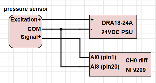
Connect 3 wire sensor in correct way NI 9209
Hello
I have several sensors of absolute pressure with only three wires (a common thread, an excitement + and signal output +). I enclose the form in pdf format. I need to connect about 6 of these sensors to my NI9209 card inside a cDAQ chassis. I also have a power supply of 24 VDC. I would like to ask about the proper connection if I want to use the differential voltage measurement.
Can I just wire the elements in the following way (left photo), or do I have to follow the recommended wiring as described in the manual on page 14, the part 'floating differential connections' ( http://www.ni.com/pdf/manuals/376909c.pdf ), right? Thank you!
Edit:
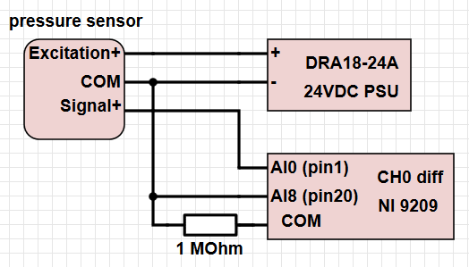
If I have to use the resistance of 1 MOhm, is it enough to use a single resistor connected between the pin of the NI of COM map and all the pressure sensors COM ports?
You need to have the input of COM on the module HAVE referenced in your municipality. However, if all your sensors are out of the ordinary even running, you need not the resistance of 1 M. The only reason why neither mentions that this connection is for incoming signals not referenced to the commune. Given that this sensor is only to give you a single output is completed, it would be much easier to just run the signal is broadcast to the module I and connect the COM to the power supply. Otherwise, you basically jump the COM signal toward the low side of each measure and the reference measurement to COM in any case.
-
We can connect the output of the sensor directly to the DAQ hardware or any interface necessary?
We can connect the output of the sensor directly to the DAQ hardware or any interface necessary? If so wat kinda necessary interface?
How to change the sensor output to match entry-level data acquisition?
If the sensor output beyond daq range is provided. What are its effects? pls answer
-It depends on your signal and the type of device you have. Your DAQ provides a package of signals? Also, what type of signal you want to measure? You must select DAQ that matches that. Take a look at the following before you start:
Getting started with NO-DAQmx: Main Page
And take a look at table 1 in the following article to wire your signal to the right:
Wiring and considerations of noise for analog signals
-You will need to use external circuitory to match the input of data acquisition range.
-You could damage the unit.
If you have any other questions, please after return. And, don't forget to give more details about your configuration, the hardware and what you're trying to do.
-
The addition of IR sensors to sbRIO-9631.
I have a sbRIO-9631 in the starter kit 1.0 and I try to connect the IR sensors to provide data more detailed than the sensors to ultrasound. My sentence connects to sensors. Any help is requested, I connected sensors to the Board, but I don't know if I did it correctly. If you know some tutorials that can help me, it would be greaty appreciated. the only tutorials I've found do far are what I use additional sensors for and not how to use them.
Hello Defested,
In the sbRIO-9631 operating instructions , that you can see on page 12, Figure 9, that the J7 connector allows you to access the analog I/o. This is where you do not use a C Series module. You can connect your sensor in several ways: CSR, NRSE and differential.
You can see the article field wiring and considerations of noise for analog signals for more information on how to wire your sensor. We recommend to use a differential connection in case you have several sensors and are concerned about the loyalty of the signals. In the case where your sensor is a floating signal source, you would want to addition of polarization resistance of AI - AI GND.
-
Out of reading 2-wire 4-20mA pressure sensors using the NI9203 module
Hi all, I'm sure that a lot of people can give a response would we apply for this.
While looking at the wiring diagram on some pressure transmitters (2 wire 4-20 mA output, direct wire), that I'm about to buy, I noticed a slight inconsistency with the wiring in the NI9203 manual. Here are links to manuals for sensors:
Following the manual of NI9203, the + ve terminal of power supply (24Vdc in my case) must be connected to the Brown Terminal in the transducer and - ve supply ground COM on the NI9203. This leaves the Green Terminal in the transducer must be connected to AI0... AI7 on the NI9203 module. This provision makes perfect sense to me. However, the user for the transducer manual suggests that the Terminal green must be wired to zero volts land i.e. COM. This configuration makes less sense to me.
My question is, the internal electronics of the transducer released still the same my current for the same measured pressure given by the curves of calibration for sensor, even if the Green teminal is not connected to zero volts?
I have a hunch it's okay, but I wanted to be sure before that I lost many years spent money / bad record pressure. This should be a matter for manufacturers of sensors I know, but I found this forum is * much * more useful!
See you soon,.
Chris
Hi Chris,
The 9203 is a device for current descendant be plugged on one side common or 0 volt. You must connect your pressure in 2 wire mode sensor.
+ 24 v DC to the positive terminal on your sensor pressure 1 terminal or brown flying lead, Terminal 2 green flying lead is connected to AIx on your 9203 and the commune of the 9203 connected to 0 Volts on your power supply.
All 2-wire device used in a current input down is still as cable + volts then 2-wire device + then then 2-wire device - (or 0) then HAVE + then common then 0 volt.
In my experience the 9203 can be rather prone to noise pick up devices with 2 sons and need a suitable clean power supply. For 2-wire devices, I take 1024 readings and then averaged to reduce noise.
See you soon
Stephen
-
Connection keyboard and mouse USB Wired stall
Hello
My computer repeatedly interrupts the connection to my Wired USB mouse and keyboard. Usually around one every 30 seconds, the connection falls for 1 to 1.5 seconds, then comes back. Meanwhile, the cursor hangs - I can't click anything, and I can't press any keys on the keyboard. For example - when I type, I have my keyboard will stop working for a while, and no text will appear. This is particularly problematic when I play games.
I tried to reboot the computer, reset the SMC and the mouse and keyboard. I also tried all USB entries on my mac (4 in total), and the problem persisted with each of them. This leads me to believe that it is either a problem with all the USB inputs, or a software problem.
I have an iMac 27 inches, mid-2011 with OS X El Capitan 10.11.6 (specifications: 3.4 GHz Intel Core i7 processor, 16 GB with 1333 MHz DDR3 memory and storage capacity of 2 TB).
I use a wired USB (Logitech G402) mouse and keyboard USB Wired (Razer BlackWidow Stealth). I have the latest version of Logitech Gaming Software and Razer Synapse installed for support.
I would appreciate help.
Check if there are updates available driver.
To check if the problem is with the USB to your Mac controller, test with a different keyboard or mouse.
To check the extensions conflicts, etc., try the startup mode.
-----
Restart in Safe Boot mode by holding down the SHIFT key at startup. Secure boot is quite slow because the operating system performs some cleanup and verification tasks, so give it time. Once you're completely connected, restart normally.
-
Give preference to a wired connection
Hi all
I'm lucky enough in my house to have a Wi - Fi network and witeless.
Although my 2015 Macbook Pro has no Ethernet RJ45 port, I installed a USB extenderes with a Rj45 Ethernet port included and now patched in the cable system.
Q: are there in all cases that I can configure the Mac Book Pro to use the network wired and not on the wireless network if it is plugged?
Then it is simply wireless when it is not plugged in?
Appreciate your help
SImon.
In the system preferences network move the Ethernet connection to the top of the list. The Ethernet connection is used and if the Ethernet connection is not connected connection method will fall to the second item in the list, your wifi connection.
-
iPhone 7 black façade. Additional sensor?
I was watching my new iPhone with the black front 7 and noticed an additional sensor to the right of the photoelectric cell. But I can't see it on iPhone before white 7 of my wife at all.
The black front there additional proximity or the light sensor?
The sensors are the same regardless of color.
-
Why am I being asked for WiFi connection on my Wired iMac?
So I installed the macOS Sierra point on my iMac and I was at the research/assistance to Siri and cards and noticed that whenever I do something that requires location services, he asked to be connected to WiFi. I don't understand because my iMac is wired to the internet via an ethernet cable. Is there something I'm missing, maybe something I am doing wrong?
Location Services can be used from a Wi - Fi connection. So anything that need localization service needs a Wi - Fi connection. You can't be located in Ethernet.
Maybe you are looking for
-
No menu bar. None of the proferred solutions work.
I'm migrating from Windows XP to Linux Mint on a separate computer that came with Firefox preinstalled. The latter seems to work well until the absence of a tab bookmark attracted my attention to the fact that I had no Menu bar. I tried all of the so
-
I can't click! When I go to a site to order something, I choose the size/style/whatever and it keeps supposedly please enter size/style/that it's when he's here! ALSO, sometimes I touched a button enter and nothing happens. It does not even let me ri
-
Why I can't download and install windows xp SP3?
I am running Windows XP Pro SP2. My internet security program is Norton Antivirus online, provided by my ISP, Qwest... When I try to upgrade to SP3, my computer is getting ready for download, begins to check the download, then goes back to prepare fo
-
How can I find deleted windows printer
Deleted printerby windows error, where can I find to reinstall
-
x 200 7458-AU2 ready to Wan wireless?
I have an x 200 7458 - AU2 and I was interested in taking a Vodafone HSPA Embedded high-speed Mobile or a ThinkPad Option 3 G Broadband card internal Mobile Broadband, given that my PCI card Mobile Broadband, I had for my T61 won't work with the x 20