Simulation of sine signals
Hello
I'm trying to simulate sinusoidal signals like speed signals. With amplitudes of Min and Max 5 and 12 V. The beach is 10 Hz to 800 Hz. The output impedance should be 100 ohms and should be rising 800 Hz soft switchable scan @ 7% per second.
I configured the sliders for the amplitudes of the 5 - 12V, as well as for the frequency range. The wave freezes when the frequency is close to 800 Hz. I configured the sample to 8000Hz rate that is 10 times of 800 Hz still no appropriate waveform.
I also hurt in soft switchable scanning configuration and the impedance.
Help, please.
Thank you.
Thank you very much Dan_K.
I love your sinusoidal signal generation method. I would watch the impedance and frequency again sweep. You have been very helpful and informative.
Tags: NI Products
Similar Questions
-
8900 Simulator have no Signal.
Hello everyone,
8900 Simulator have no Signal. It shows OFF instead of signals.
What should do
Hello
Click the 'Manage connections' and select the Mobile network.
Thank you
Kanak
-
Two timed in a single parcel sine signals
Hello
I enclose my VI, and I need help to draw the waveform.
Each symbol (0 or 1) have different frequencies. I would like to draw each signal one after another. (like a waveform of the FSK)
I am trying to build my own FSK.
So far, each signal is display one then the other.
Thank you

Hit Ratatouille,
The display of graphics for one signal after another, click with the right button on the graphic on the front and replace it with a graph in the form of wave. I think that this action has resolved the problem you mentioned. The functional difference between a waveform graph and a waveform chart is the way are handled the x-axis. For the chart, the x-axis is in real time, while for the chart, the values of x are an entry. In your case, the generation of sinuses makes the sine waves, but each generation has the same values, X, so the best you could do would be to overlap.
Hope this helps,
Luke W
-
How can I generate sine signal long 10ms?
Hello world
I would like to do next: generate a sine or a DC signal for a period of time, 10 ms, that is to say after that, I want that my trips to Earth, so that the next time that I run the program. I use DAQ Assistant and DAQ 6211.
Any help or advice will be great!
Best regards
Pero
pero_kr wrote:
Let's say I have a while loop in my program. When I press "run" the loop runs over and over again, until the stop condition occurs. How long (in milliseconds, microseconds or nanoseconds) takes to my PC to do the operation in an iteration of the loop?
Hope this time was make myself clear. Thank you much for the help.
That depends entirely on what is inside the loop, and what does your computer and what operating system you are using. You cannot create a deterministic loop with a non-deterministic operating system like Windows. An iteration of the loop could take 5 msec, or it might take 5 seconds if the OS thinks it must go off and do something very important, like updating your computer to solve all these security holes that has Windows. You can use call loops, but those who are not guaranteed to operate at exactly the specified frequency since you are at the mercy of the operating system.
I still don't see why this information is important to you. Did you do as suggested and watched the examples supplied with LabVIEW and settle with DAQmx? They show you how to do the generation continues.
-
generation of signals DAQ 6133
Can use of BNC-2110 and DAQ board 6133, I generate a sine signal and the signal sine output?
Hi WG_23,
Wondering if you can use your 6133 to generate a sinusoidal signal and connect it to the BNC-2110 to connect it to something else? The 6133 does not have the analog output capabilities, so you will need to do this, use another card.
Best,
-
Why the signal are seen in the way IQ?
Hello world:
I'm confused on a phenomenon I have seen since a simple demo. The demo is that a sinusoidal signal is transmitted by the USRP by I traced. I have observed sine signal to two I have paths and Q of the signal for the same USRP. Signal path Q is not smooth like the I traced and the amplitude is lower. However, I think that the Q path should not exsist signal. I understand this problem as shown in the figure and the attachment is the demo
The USRP allows Tx and Rx LO are independent with a common reference, allowing you to tune in at two frequencies at the same time. It also means the phase of are of two different LO. This means that the acquired signal scatter energy between I and Q, but will have a common complex amplitude. If the traces on a constellation diagram, what it would look like a rotated constellation.
-
generate the signal of decimal number
Hello
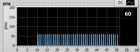
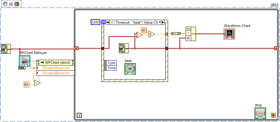
I have a program that calculate the heart rate from the ECG signal. I want to show the beats per minute on a graph with 60 s of the plot of the story.
Since the vi who calculate the heartbeat I get output the string with the number, only when the wave of the tip, then I convert it to a number and then I place the offset of a simulated DC signal.
(In the table below the beats per minute are always 60 because I'm simulating a sinusoidal signal with 1 Hz).
------>
It works fine, but I'd like to see not the summits but a continuous line from one point to another, such as interpolation.
in this case, it would have been a horizontal line to 60 BPM.
I thought to store the last value of the chain and keep it frozen until the next update of value.
Do you have suggestions on how to do it?
Concerning
Not clear what you get in the form of numbers, seems that you get too many zeros, and you get a decimal number or another 'dynamic '? value?
You pulse-rate information could be ~ 45 to > 180 values per minute!
You display the exact story of a minute? Maybe (keep the last ~ 300 values with timestamps and use an XY diagram) a graphic story can be configured to display
wait... Here's one way:
I fed a chart (with 256 points in history), with a waveform. the wfrm has only a single value in the array of values and a t0. The chart is configured to display the 60 sec. Seems to work
My simulation will display a min rate of ~ 45 BPM, but you can beat him

-
increase in the frequency of car to simulate signal vi
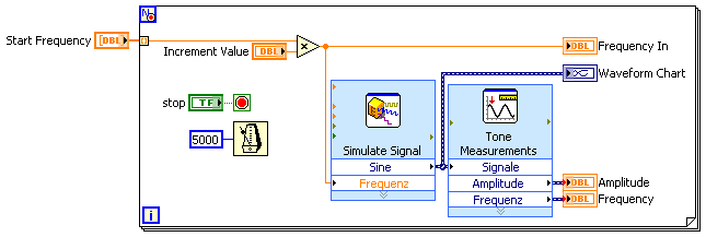
Hello world. I'm pretty new to labview. I want to increase the frequency to a vi simulation using the matrix of numbers of signals. the loop must browse the table and a frequency that will serve him entry to the simulation of output signal vi every 5 s change the frequency of 10 Hz to 20 Hz to 30 Hz and so on until the end of 1 kHz.
attached is a vi that I wrote, but something doesn't seem to not be accurate
Hi marco,.
in general, this question boils down to: think the stream!
What is the purpose of this inner loop FOR?
Why not use one loop at all?
Maybe like this:
-
Hello, I'm trying this arbitrary signal by arbitrary simulation of output signals express VI. I want an exit point out analog of the DAQ USB 6281 every second. When I said to output a point by iteration I get error 200609 say the selected buffer size is too small (selected the size of the buffer: 1, minimum buffer size: 2) how can I change the buffer size? attached if my VI, just go under the 1 'arbitrary' case and you'll see my VI Express with points iv series.
But you are passing an array many points so you should have to index this table point by point by putting the DAQ Assistant, in a loop with a delay of 1 sec. You can also spend the whole wave and specify a frequency of 1 Hz in the DAQ Assistant.
-
measurement of signal of phase
I want to measure a signal in phase and out of phase, how do I set up a VI to measure them separately?
The phase of a signal linked to what?
For a measurement of phase, you must always a time reference (or a reference to another signal phase)
If you have a rude sine signal, you can try vi tone detection, the output is of amplitude and phase, so just calculate has and b (see complex number functions)
Or you use the FFT vi and get the bins already complex at frequencies which correspond to those you are looking for, if all goes well except if you match the input data (or do a bit of math more
 , BTW is what makes detection of tone vi)
 -
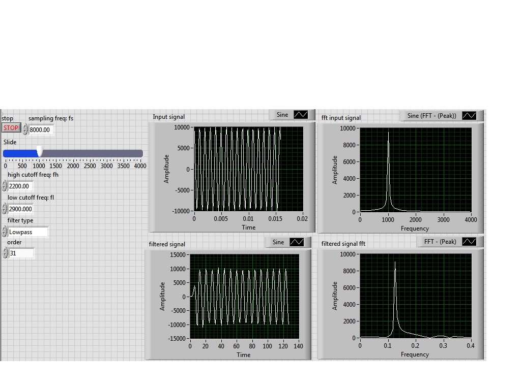
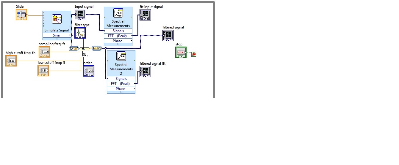
I'm simulating a sine wave at approximately 1000 Hz (I'm variable according to the frequency with a slider), I would like to pass this signal by a lowpass filter (butterworth) with a high frequency of 2200 Hz cuttoff and a low pass to 2900 Hz frequency. However, the output after the filter frequency seems to be lower in the order of a thousand. the output frequency is about 0.1 Hz.
Y at - it someone who can guide me please to solve this problem, I tried different filters and I'm still having this problem, it would be incorrect sampling?
I enclose the block diagram and the front panel
Because you use express screws and the type of dynamic data...
You convert the signal of DDT (which contains the clock information) in a table DBL to perform filtering. Take it a DBL array (which contains no data of timing) and converted it into a DDT (which now contains no data timing). That's why when you try to view and analyze it you have lost all the data timing (frequency).
If you were to exit table DBL of your filter and build a wave form and provide the dt to the waveform of the sampling frequency control, then it will work.
Better yet, ditch the DDT and use waveforms from the beginning
-
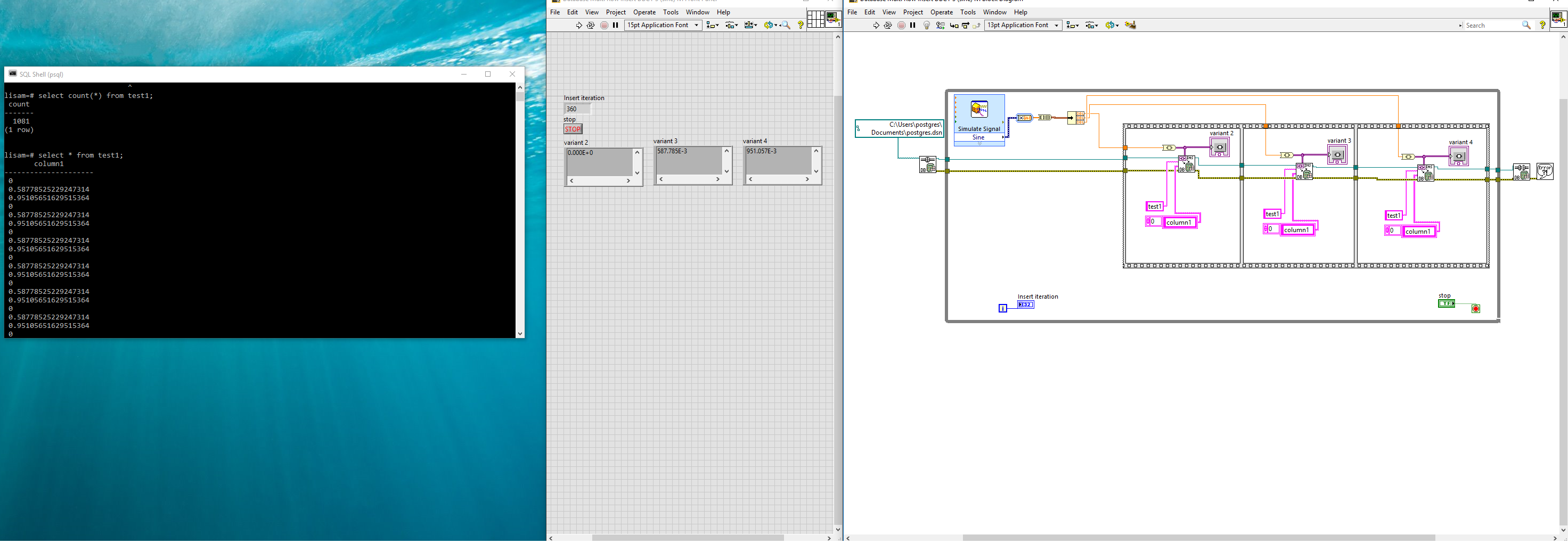
Database Connectivity Toolkit (insert multi line)
Hi all. I recently got the toolkit of connectivity (DBCT) database on LabVIEW 2016 and I try to insert several rows in a database.
Using a sine signal input I tried to insert 50 rows in an iteration, but each method I tried returned 50 values in a line. The end of the constant of the line and table using chain worksheet, returned what looked like 50 lines, but when I questioned "SELECT COUNT (*) FROM... "the number of rows equals the number of iterations.
On another post on the forum, someone suggested that it is not possible to insert several lines using the DBCT. Can anyone confirm this?
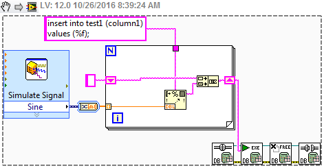
I wrote a code that allows me to insert 3 rows in an iteration, under a single connection. However, this method is very time consuming and would not work for large amounts of data.
Can anyone think of a better way to do it?
Thanks in advance,
Lisa
Create your own query, and use the query execute VI.
-
Digital and analog gain in Script mode
Hello.
5422 module can change the voltage Vp-p order of 05:54 V.
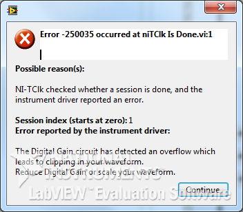
But when I use the property node - digital Gain, after setting the 1.1 V and return to its previous value (V 1.0) occurs the following error:
And when generating a signal of amplitude of 1.1 V signal very distorted.
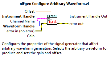
In niFgen configure Arbitrary Waveform VI it is a Gain parameter to control the standard signal (which I understand). Is there something similar for the Script mode?
How to access the analog Gain?
And in general, how to properly use the analog and digital gain in Script mode?
I apologize for possible errors, but the example is not yet complete.
Max O.
Developer of software and engineering,
TeSLa.
Hi max_i,.
Since the ownership of digital Gain help file:
"Specifies a factor by which the digital signal generator multiply data generated before the conversion of an analog signal in the CAD." Saving digital greater than 1.0, the product digital time gain the data generated must be in the range ±1, 0 (assuming that the floating point data). If the product exceeds these limits, the signal generator cuts out the output signal, resulting in an error. »
Digital gain requires the data, being always standard-1 to 1V. The output of 'Ladder' to 'normalise Waveform.vi' here is generally superior to 1, which causes this error 250035. If you search for the property similar to the entry of 'Gain' on the ' configure Arbitrary Waveform.vi ', I advise to use the 'Gain' on the tab 'Arbitrary signals' property in the property node.
Looking at your code, it seems that you try to build pretty standard signals (sine signals). Is that this will change in the future to more complex waveforms? If not, I wouldn't recommend watching one of the examples in the example LabVIEW finder, I find "Sequence of Arb basic Fgen" quite useful. If you want to make scripts as well, I would recommend the example "Fgen Arb Script".
Thank you
David B
National Instruments
Technical sales engineer
-
Ideal no RC Impulse Response vague question the quadrature
Salvation OR team,
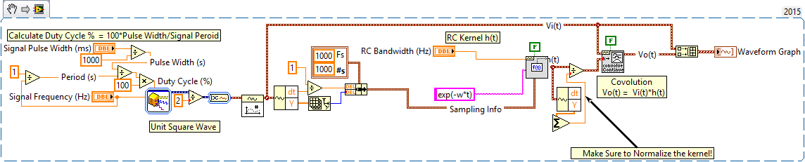
I have a little trouble understand why the amplitude of the response of my simulated square wave signal, when passed through a non-ideal answer RC filter, is incorrect. Qualitatively, the form of the answer seems correct, but the range is wide.
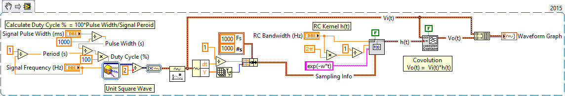
I'm generating a square wave (where you specify the width of the frequency and pulse), the amplitude is set to 1 and the offset is also 1 for the square wave goes from 0 to 1...
Then, I build the core of impulse response indeed RC ((1/RC) * exp(-t/RC)) using the formula of wave Vi, and finally, I use the continuous VI of Convolution to convolution of the signal with the impulse response of RC square wave to generate the output signal...
For example, this is explained in the following link:
http://Web.CECS.PDX.edu/~ece2xx/ECE222/slides/ConvolutionIntegralx4.PDF
Although, I think the author may be typo in the amplitude of kernel (I think it should be 1/RC and not RC) but the rest seems fine.
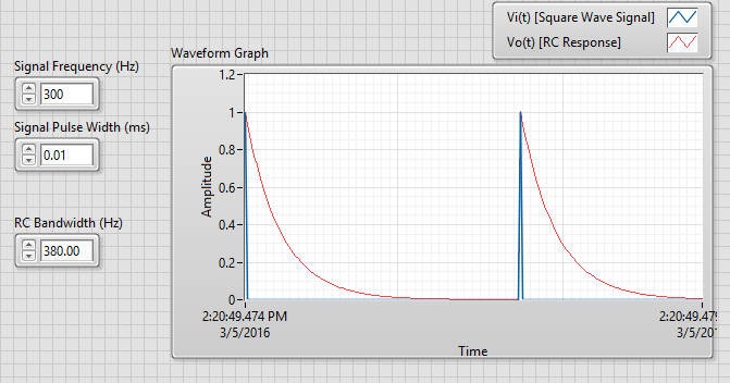
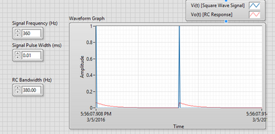
In the attached VI, use a frequency of 300 Hz, pulse width of 0.01 ms and RC 380 Hz bandwidth Signal.
RC 380 Hz bandwidth would be a time constant RC of ~ 2.6 MS, when a square wave with a pulse width unit< than="" 2.6ms,="" the="" resultant="" response="" signal should="" have="" an="" amplitude="" of="" 1="" (matching="" the="" unit="" square="" wave="" signal="" here)="" and="" fall="" off="" appropriately="" as="" e^(-t/rc)="">
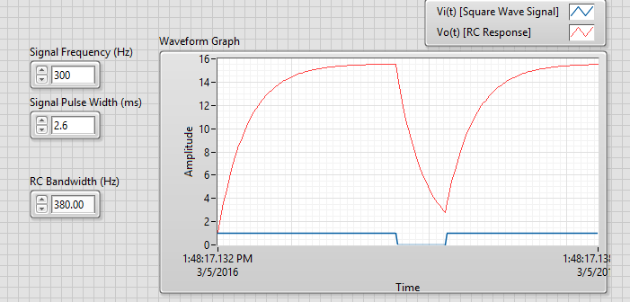
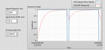
This seems OK when running the simulation. However, when I increase the width of the impulse to say 2.6 ms, (which should show a refill of the RC circuit to an amplitude of ~0.5 and then discharged as e ^(-t/RC), the amplitude is too high...
Have I a gross error in my understanding here, or maybe I use one of these VI incorrectly?
Thank you for your help and time in advance!
In fact, I made a mistake in my interpretation of the correct amplitude in both cases, I presented. I was still unable to resolve the discrepancy here, but thanks to this post, I managed to solve the problem. In this case, we need to 'normalise' the core of convolution to the 'sum' of the elements in the data of y of the signal of the nucleus resulting. I will post the solution here in case someone else runs into this problem.
-
Hello
I just started using an NI USB-6008 box. At this point, I don't need to fill all the specific tasks other than learning to use the device. I used a fair bit of LabVIEW but never with this kind of material, and I would like to help to understand it please.
In particular, I have attached a VI in which I try to get an analog signal through the USB-6008 and read again (also with the USB-6008 - I wired the pins together). However, I do not understand what is happening when I run this VI. I expect the output a sine signal of 10 Hz for 1 second, 0.1 seconds record and see 1 full cycle of the sine wave. In practice, I read about 10 cycles and constant tension then. Presummably, this means that either the reading continues for more than 0.1 second, otherwise the output signal is more than 10 Hz.
I also tried to use the related calendar DAQmx screws with the output pin to try to adjust the output rate (samples/s) but everything that I've tried return errors. I also tried to open some examples NOR, but these errors returned as well and I still just try things on mine.
Did I miss something obvious here, but any help would be appreciated!
Edit: I had to update this post & attached VI I had made mistakes. The default values on the front panel show what I see after the execution of the VI.
Orbital Hi,
As far as I know, you will need to use the DAQmx Read and VIs write in loops and functions of synchronization to determine data rates you want.
I also did a quick search and found a white paper which you may find useful: http://www.ni.com/white-paper/9541/en/
Kind regards

Maybe you are looking for
-
HP sales (Off shore mumble mouth broken English addition)
Recently, I called your sales team and asked to extend my warranty on my HP Touchsmart PC 1050 520. I was initially connected with an agent based in the United States (United States!) but when he found out, I had a Touchsmart it redirect me to an age
-
Fake phone presents in the forum
As much as I see my grip in the discussion forum, it is a bit beside him, flip phone even though I specified that I have a Droid X. This can be corrected?
-
The re-registration of the computer
Computer me given by family member. How do I register myself? Can I just install a windows program, I own on it and then re to the register myself? Or just do a user in my name account? Oh it's Windows XP home Edition 3SP I have my own WinXP Home B
-
Retrieve files from the old hard drive
I have an old desktop pc that was running windows xp. I started the upgrade to vista but lost the product key and never managed to get a new one. There is an error message when I try to start the pc. Im not interested to fix it, but I want to get som
-
OfficeJet 6600: HP Officejet 6600 will analyze a computer Windows 10
I have a HP Officejet 6600 - H711a/H711g e-all-in-one printer. Since the upgrade to Windows 10, I was not able to scan to the computer. I am capable of copy and print without any problems. I've done several reboots, power disconnects and reboots and