runing an algorithm in FPGA in Veristand
the app is like this: a model (dll) is imported to the Veristand, and this model will be run in the aim of RT. We have another algorithm, and we intend to deploy in the FPGA.
the model running in the taget RT has an input and an output signal, the algorithm also has a signal input and output. so my question is: How can I deploy the algorithm in the FPGA, and map the input and output signals?
wenluo
You can create your device that is customized by using the custom device model.
Go to C:\Program NIUninstaller Instruments\LabVIEW 2015\vi.lib\NI Veristand\Custom Tools\Custom device device model tool
Then open and run 'Custom device model Tool.vi' with some parameters.

This operation automatically creates custom device and you can customize yourself.
Details can be seen here.
Tags: NI Products
Similar Questions
-
Download Bitfile to Flash on FPGA in VeriStand
Hello
I was wondering how to download a FPGA bitfile for flash memory on a FPGA using VeriStand. I use a PXI chassis and a FPGA PXI R series.
I hope that the answer is
(1) configure the FPGA VI to run when loading on FPGA
(2) open the VeriStand System Explorer, set the initialization of the system to run a system to reboot definition.
(3) deployment.
Or is the bitfile stored on the hard drive to the chassis and then imported on the FPGA whenever the chassis is started?
If I cancel the deployment of the system definition file I guess the flash on the FPGA is deleted, is it true?
Thank you
Brent
Hi Brent,
I heard R & d today. VeriStand uses the open FPGA VI reference, which means that the bitfile will not be replaced if it detects the correct bitfile already running.
"(Par défaut pour certaines cibles FPGA, cette fonction s'ouvre et exécute le VI FPGA compilé sur la cible FPGA si le VI FPGA n'est pas déjà en cours d'exécution)." - 2012 help FPGA open Reference VI.
When the system definition is canceled the FPGA is reset to zero, which is the default behavior of the close FPGA VI reference.
"Farm the reference to the FPGA VI and resets the VI if no other references to the VI is open. Reset of the VI returns VI orders and States flags by default defines global variables uninitialized shift registers default values and clears FIFOs. "- 2012 Help close FPGA VI Reference.
Zach
-
ThorLabs DET10A connection in coupling AC 50 ohms digitizer
Hello
I'm scanning the signal of a ThorLabs DET10A using an adaptation NI 5772 AC FlexRIO Module. The DET10A is 50 ohms and the 5772 is 50 ohms, but a direct link between the two does not work. I expect pulse height N and width M, where N is the order of 1 V and M is the order of 10s of nanoseconds. Yet the digitizer shows N * 0.1 pulse height and pulse width M * 25. If I turn off the DET10A, does not change the 5772 reading. If I re - turn on the DET10A, reading the 5772 is exactly the height N and M of width, but the signal breaks up to N * 0.1 and M * 25 for a second or two. It's as if the 5772 is cast too much current or roughly the filtering of the signal. I tried to connect the DET10A to an O-Scope Tek. When coupling DC, the signal range is exactly N and M of width height. When the field AC coupled with a 1 M ohms impedance, signal is perfect as well. When the field of AC coupled with an impedance of 50 ohms, I see almost the same type of behavior decomposing as on the 5772-AC. We tried 50ohm closing the DET10A and measurement in parallel with the terminator. The scope and exposure 5772 mitigation and the ringtone I'd wait wrong with impedance, but the signal does not decay in this configuration. Mitigation is somewhat tolerable, but unfortunately the ringtone will beat the algorithm on FPGA FlexRIO module. Does anyone have suggestions for the digitization of the DET10A with a digitizer in coupling AC 50 Ohm terminated?
Thank you
Steve K
Thanks David,.
An EE figured out here the 5772 AC and AC 50 Ohm terminated Tek scope matching did not provide DET10 through a path to Earth. All is well with the measure now. Please consider a KB along the lines, "Use coupling AC scanners with signal Sources biased", or something like that.
Kind regards
-Steve K
-
RTD & Thermocouple sensors Simulation
I am very new in VeriStand, and I would like to ask you what is the best way to implement simulation of VeriStand sensors.
I should implement simulation of RTD and Thermocouple VeriStand probes.
Problem with temperature sensors are mathematical equations has high order (RTD's 3rd order (it is not so bad) and Thermocouple is 9th order).
What I have to put in place this equations on FPGA or VeriStand could calculate for me in the real-time engine (and then VeriStand implement on FPGA and channel AO level could be applied only something like reaction/compensation currents of excitement to HAVE it)?
What is the common practice to implement simulation of temperature sensors. Of sampling/update for temperature sensors is generally very low.
My configuration is:
- Home PC - development tools
- PXI controller - OR VeriStand engine RT
- RECONFIGURABLE - PXI map
- NI9151 - R series expansion chassis
- C - Series AI & AO (electric implementation)
I'm looking forward to you answers.
Peter (CLA & CTD)
Thermocouple (9th order) I have implemented on FPGA as a look up Table. Look-up Table initialized by the equation of order 9th in the range of the required values.
RTD (3rd order) directly implemented on FPGA. VeriStand send all settings from all periods.
-
Mode of scanning/FPGA for a CRIO by Veristand
Hello!
I have a small error using my CRIO 9081 use with CAN communication, here's what I did:
1. I use the CRIO with scan mode and customized it "Scan engine" and Ethercat for show my analog modules under VeriStand, it's ok
2. I use the CRIO with FPGA Scan interface (together under Labview) to detect my modules CAN, also ok
3 - then I wanted to see the CAN and analog modules, so I use this page:
http://digital.NI.com/public.nsf/allkb/0DB7FEF37C26AF85862575C400531690
And here's my problem:
with this method I am able to see the two modules with the custom device 'analytical engine and ethercat", which is really nice, BUT, impossible project VeriStand, the error message asking me to turn the chassis using FPGA, but then I lost the analog module...
So is it possible to run a project Veristand using both Scan and FPGA interface mode?
Thank you very much

Hi Vincent,.
When you tried to implement, you use the procedure described in the following document in the section use of Scan Engine and EtherCAT with NI 986 x custom device modules XNET ?
From what I remember, because you use a cRIO-9081, you will need to compile an empty bitfile for your target and place the controller in Mode FPGA hybrid mode on your chassis.
Could you post a screenshot of the error of deployment, you see?
-
Adding personality to VeriStand FPGA
Hello
I am trying to add a personalized my VeriStand configuration FPGA. I use PXI-7853R in 1044 with PXI-8110 controller chassis.
The FPGA model itself is running properly and the fpgaconfig file is modified. The fpgaconfig and the bitfile are added to the propper directory. Now when I want to add it as a target FPGA, I get the following error:
***********************************
LabVIEW: File not found. The file could be
moved or deleted, or the path may be incorrectly formatted for the
Operating system. For example, use- as Windows path separators: on Mac OS
X, and on Linux. Check that the path is by using the command prompt or
File Explorer.=========================
NOR-488: The non-existent GPIB interface.
C:\Documents
and All Users\Documents\National Instruments\NI VeriStand
2010\FPGA\PXI-7853R HighSpeed Interfaces.lvbitx***********************************
I checked
but the http://Digital.ni.com/public.nsf/allkb/2FA525A8585A92E9862566EE002A3755 was not able to address the issue.
I enclose a few screenshots to give an image of my installation.
p.s. I'm not planning to use the GPIB.
Error 7 is a generic "file not found" error in LabVIEW. Unfortunately, I think the NOR-488 driver also uses the error code 7 for a GPIB interface to the nonexeistent, and the error description lists all possible sources. In your case, the error is due to a missing file and has nothing to do with the GPIB.
I re - check the bitfile name in the .fpgaconfig and verify that it is the path listed:
C:\Documents
and All Users\Documents\National Instruments\NI VeriStand
2010\FPGA\PXI-7853R HighSpeed Interfaces.lvbitxIf you can get the files .fpgaconfig and .lvbitx, we try here and I hope that give you the best guidance.
-
FPGA VeriStand personality is late? and latent FPGA data processing
I use a FPGA 7853 (only) in a SMU 1071 chassis with a controller 8135 and run VeriStand 2013 SP1. At the end of my test, I want to ensure the integrity of the test, which includes the audit of the FPGA interface is never late.
I first thought to expose the terminal 'Is?' late as a channel, but then I noticed it isn't really an account, it's just a flag. In addition, it seems that this flag is not locked, it does report by iteration of loop interface. This makes me think that I alarm an VeriStand on the later is for VeriStand FPGA interface design? channel. Am I correct, and if not, how NOR have I use East late? terminal?
As the DMA in the FPGA nodes then never expire, there no sense watching the Timed Out? terminals on the FPGA. But the effect of a timeout will appear in the East towards the end? Terminal Server. I'm tempted to change the end is? U64 to a real number in the number of late? the defined indicators synchronize to the host VI. is there a reason to not do this?
How VeriStand manages a FPGA end? If the RT side of the DMA buffer became more complete, data from the FPGA would be more latent, which could lead to the instability of the system. Hopefully the VeriStand engine should purge the latency of the data, but I don't see anything in the FPGA interface which would facilitate this.
Thanks for your help,
Steve K
Hey Steve,
If the PCL NIVS reads this flag as true, it incrememnts the County of HP system channel.
For the question of FIFO depth: The PCL is always expected to read and write a # fixed packages each iteration (as defined by the XML) and FPGA always reads and writes the same number of packets of each loop of comm iteartion and since the timeout is set to-1... orders may not be combined. Packets act as a handshake.
-
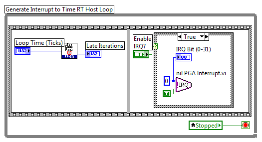
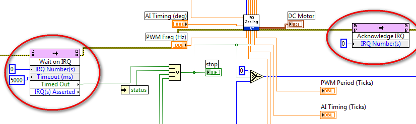
FPGA-IRQ in the custom VeriStand FPGA VI?
Hello
I built an FPGA VI custom to use in VeriStand. This FPGA VI contains the following IRQS:
Now I also have a VI in LabVIEW FPGA code that I want to use VeriStand. I changed it to use as a custom device, so I removed all of the FPGA code and replaced by indicators and controls so that I have can map device custom personalized in VeriStand FPGA.
But there is always the FPGA-IRQ, and I don't know what to do with these two nodes:
How can I use these knots in my VI of custom device or generally VeriStand?
Thanks for your help.
Kind regards
HScho
So finally I found a solution:
I disabled all the stuff IRQ. The main problem was that the model I wanted to use in VeriStand was inside a While loop. I had to remove the loop While VeriStand itself being the loop.
Kind regards
HScho
-
So, I can't understand why this is happening...
If I deply the VS project to the RT with enabled FPGA (RIO0 and RIO1) target, it cannot deploy every time. If I activate RIO0 and RIO1 - it works. And same sense reverse (enable RIO0 and disable RIO1) so I know that my FPGA code and the *.fpgaconfig file work properly.
Anyone know why this is happening? I did some research but did not come with anything.
Thanks in advance for the help.
big shot in the dark here...
Assumes that you have a chassis 18 locations, you use NIVS 2011 SP1 or an earlier version, and the cards are in different segments bus of your chassis (aka, pretty remote)?
If so you must go to MAX, select the controller-> hardware-> frame-> triggers (the bottom tab)... and route of line 0 onset of the RIO device which is "BOLD" blue in your system definition (which is the specified master device on the chassis page)
If I get this with no error information at all and a total guess I think I deserve a Bravo. If not too bad
-
cRIO 9081 to the 9144 expansion chassis. FPGA engine mode or scan?
Our installation program runs VeriStand on a chassis 9081 cRIO using a FPGA personality. We wanted to add an ethercat expansion chassis 9144 to the system. Don't support the cRIO and expansion mode personality FPGA chassis runing VeriStand? I can't find much information about it, other than runing the system using the analytical engine.
Initially, we tried to run our system uisng the analytical engine add on, but the system had problems with the NI 9213 16 Ch thermocouple card. If one of the inputs is open it read the rest of the channels open. For example, if channel 5 is open, the remainging channels 6 to 16 would also read as at the opening. For this reason, we configure an FPGA personality to read inputs and outputs.
Thank you
You can do it. But you need to compile the FPGA in a hybrid mode:
http://digital.NI.com/public.nsf/allkb/0DB7FEF37C26AF85862575C400531690
-
Reverse and pseudo inverse Matrix on FPGA
Hi all
How can I calculate matrix inverse/pinv on pushed more logical clock (*.gcdl), for FPGA? (Labview Comms 2.0)
Maybe someone has a solution for this task? Or that the best algorithm I use for this task?Thank you.
Hello togoto,.
We have matrix Inverse and matrix screw Pseudo-inverse for code side host, but these are not supported on FPGA. The reason for this is because without a known matrix size, there is not a way to implement a dynamic matrix math function (the compiler couldn't know how many resources which requires). If we consider that more algorithms of inverse depend on the division, which is very intensive on FPGA resources, which provides another reason why we would be unable to put implementation in CDL.
That being said, Comms has Matrix multiply and transpose the matrix of features that you can implement in CDL. Because for a long time the matrices are always a fixed size and uniform, you can implement a custom algorithm to achieve pseudoinversion and matrix inversion. It would take careful pipelining to ensure it worked in a single clock cycle.
Could you elaborate on what exactly the application is supposed to accomplish? If possible, the math movement matrix your screw host-side may be the best approach.
Best,
Daniel
-
NEITHER 9871 best way to create the customization to veristand
I would use a NI 9871 module with NEITHER veristand to connect with over RS-485 devices using the modbus Protocol. I know that this device can be used in mode of scanning and orders VISA, but won't work with the custom device EtherCat Scan Engine.
I was wondering the best way to change NOR veristand.
1. Create custom FPGA personality and write the drivers to directly interface with the ports on the device by modifying cRIO Modbus.lvproject http://www.ni.com/example/31166/en/. Expose the commmands as channels passed from the FPGA personality to the workspace and command those from the workspace.Current limitation, I am unsure how to modify this into a custom device or model due to the FPGA IRQ in the RT application used for timing. Can this be included in the custom device?2 use the 9871 in scan mode and write a custom device to interact with it using the VISA. Deploy with e/s Modbus device custom servier and send orders to shared variables in the workspace. It would be easier and more robust driver, but I'm not sure how to implement if my other 7 modules use the custom scan engine. I can't apply it in scan mode and the other seven in FPGA because of the DMA only 3.
3. change the Scan Engine custom device to support 9871? Not sure if this is possible.
Thank you
Mike
4. do not use the NI 9871 and use the serial port on the Crio with a custom modbus device. This leads to a problem of timing, as five devices I want to interact with, I a port. Can reduce functionality.
An update, since I've found a method that worked well enough and was easier than I expected.
If you use the cRIO in scan mode with custom device of the scan engine, the ports will appear in MAX for the module 9871. I didn't when I started at the beginning of the post above. From there, you can use all the functions of ports similar to the rs232 port which is included on the NI 9074.
I wrote a custom device which opened a VISA session at my port and then was able to apply the code I need to communicate with my camera rs485. I worked with modbus Protocol and functions worked within my device custom without modification. I could also adjust VISA settings in MAX and could run a VI of my pc that would send/recieve data ports. This will be useful as an additional way to test or change the settings on my outside NIVS rs485 devices.
It should be noted in my last post, deploying a Modbus Library did not work. Shared variables of Veristand work incorrectly with the variables that they have been configured in the modbus library that I deployed. I was able to set these manually from the Distributed System Manager. I could also do standard shared variable variables and would update the workspace NIVS in distributed systems manager, they would not change the value in the modbus server. I decided to abandon it and create a custom device that just use VISA vs. shared variables.
-
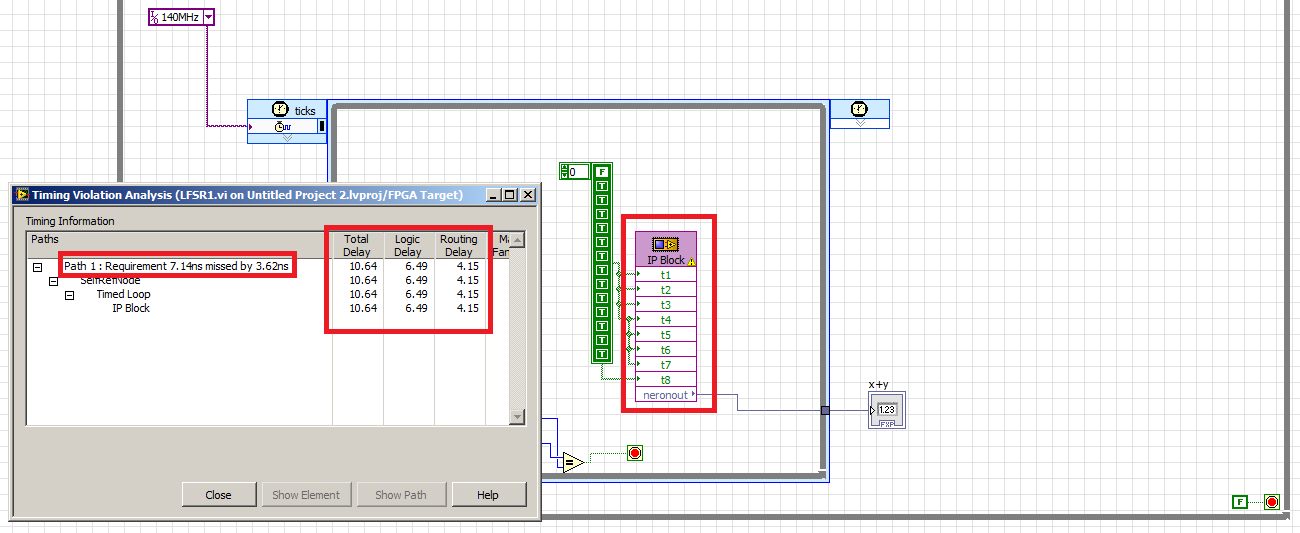
Violation of timing in labview fpga
Hi Member
in the figure below you can see a time violation was happen in my IP integration
the problem is to know how to calculate the maximum frequency of the numbers appeared in the Red block?
I'm trying to connect to 150 MHZ, violation of 140 MHZ time also appear!
What is the maximum frequency of work for this IP block?Delay of logic is the delay by real choice tables, DSP blocks, etc. The delivery time is the time between the logic of 'true '. the delay between the logic blocks, including the time to go through the switching matrix. Generally, you cannot reduce the delay of logic without having to rewrite your algorithm, but you can reduce routing delays by inserting records in order to let the tools move logic on the chip.
And you've stumbled upon one of the great mysteries of the use of an FPGA. Sometimes changing the clock frequency just cause tools to generate a different code that works better. In your case, it seems that the tool could do better and hit 100 MHz. With your original 140 + MHz tool understood from the beginning that it would not reach this rate then it stopped soon before making other optimizations, showing you as well as he guessed couldn't make it around 90 MHz.
-
Increase the rate of target on Veristand
Hello
I am a novice user of Veristand. I'm doing a feedback from control with the help of a compactRIO:
RT OR cRIO-9024
Chassis cRIO-9113
9220 and 9263 modules.
I use Veristand with a compiled since Simulink model to make my will.
I want to be able to reach frequencies of 10 KHz loop or more, but the loop of the target rate freezes the system when I try to go beyond 700 Hz.
Is it possible to do?
My model is very simple, for now, I'm simply connect the 9220 1 entry at the exit of the 9263.
Thank you in advance,
Kind regards
Rates
Hi prices.
The 9024 is unable to run NI VeriStand at your desired pace. As you can see, it tops out around 700 Hz. There are several reasons for this, but the end result is that you will need different hardware to run at your desired pace. A 9082 will be much faster, and a SMU-8135 will be even faster than that. Also if you use PXI, if you only need of IO and no treatment only Co, our PXI DAQ devices allow you to hit the NIVS rates much faster than the PXI FPGA devices.
Good luck!
-
I use the timekeeper of FPGA to synchronize my 7966 FlexRIO FPGA to the system clock of the controller of my SMU. It works well and give me about 5 of error.
A PPS (from an external reference) can be used to increase the precision of the FPGA timekeeper? If so, are there algorithms (FPGA VIs) already developed for this?
Thank you
XL600
If you download the 1.1b0.zip FPGA timekeeper from the link below, it will download the Timekeeper.lvlib FPGA, documentation, examples and timekeeper. In the folder of the example, there is an example that shows how to synchronize to the PPS.
https://decibel.NI.com/content/projects/NI-TimeSync-FPGA-timekeeper
Maybe you are looking for
-
"Suitcase Fusion has detected an incompatible version of the Core FM" How can I solve this problem?
Hi, when I turn on my mac, this note appears: ' SUITCASE FUSION has detected and an incompatible version of the Core FM. " Anyone know how to fix this? Thank you in advance! :-)
-
How can I update my newsletter subscription preferences?
I've updated my email address in my account profile. Unfortunately, this is not update my new e-mail address in the management of your Mozilla newsletter subscription page. So now, I get an email for certain things on my new email address and Newslet
-
I lost all of my contacts - would it because I was on Skype on a different laptop 2 days ago? How can I get them all back? Thanks, has soon Jon
-
HP Pavilion dv7-3067nr does not start
My laptop does not start. Screen remains blank. All the lights are on. Numlock and caps lock will Flash twice. I removed the battery, memory, HD and all the accessories. same mistake.
-
Compatibility problem with Vista and iTunes
I downloaded iTunes 9 on my Tobisha laptop Satellite last night and put about 2.5 GB of music on it. I didn't upload the music from the internet. I used MP3s, I had for a few years. When I went to boot up the laptop this morning the loading process t