Simulating a source PWM?
Is it possible to simulate a source PWM?
It could be a factor of control tension of market at a predefined frequency.
Thank you.
Hello
You can read this our KB (knowledge base), there's even a sample to see how it works.
Link
http://digital.NI.com/public.nsf/allkb/EF391C48CF71AE4F862571B900644F84
EDIT: I forgot to add that according to the version and the type of multisim, there is a whole section for PWM and other uses under the family of POWER .
See you soon,.
Tags: NI Software
Similar Questions
-
Hello
Before I ask my questions, I want to describe my problem:
I would use VeriStand on a PXI system for simulation only. The simulation includes different types of sources such as Maltlab-Simulink-models, MultiSim SPICE models and code LabView for FPGAS-programming. Simulink models are available as a dll-file, generated with 'Real-Time-Workshop' and 'Simulation tool Kid. " They need to generate heavy duty, calculated by the modulation of the vector space and model the performance of a special converter. The MultiSim model will be transformed via a special VI in LabView code. I can generate code VeriStand (--> NI VeriStand--> Generate tools...). The PWM duty cycles of this dll matlab above are for LabView FPGA code entry. This will be the entrance of the gate of the tansistors of the MultiSim-model. Means, space vector modulation generates tension of the door and get the FPGA code to the ports of the inverter model.
I am new in programming with VeriStand and LabView. I don't know how I can handle this. But NEITHER says it's possible. So my questions are:
Is it possible to use VeriStand with more than one device Costum and simulate as a whole simulation. How can I associate different files.
If this isn't the case, that I have to build a LabView Vi, where all the different sources of models are included.
Is a walkthough or a user guide available, that I can use to fix my problems.
I hope you can help out me. I need it for my bachelor thesis very fast. Thank you for your attention.
Best regards Andre
Here is a document describing how to create compiled LabVIEW templates and import them into NI VeriStand:
http://www.NI.com/white-paper/12785/en
The following link is a more general page describing several model and their support environments in NI VeriStand:
http://zone.NI.com/DevZone/CDA/EPD/p/ID/6488
Some additional modeling environments are supported, but not necessarily listed here since this is a growing list. In addition, since NEITHER created a strategy of open model interface called NI VeriStand model framework, it would be possible to connect new types of sources of model in NI VeriStand without too much work. Then the mapping tool, you found, makes the magic of easily to configure the connections of logical data between models. You can also easily transfer each model to the individual processor cores, which contributes to the speed of calculation for system-level simulations.
-
by using labview co-simulation, how to control the PWM market factor in multisim
I am new to the use of Multisim with LabVIEW using co-simulation. I would like to ask if there is a PWM component in Multisim, which can have its cycle have to be controlled using LabVIEW? I have an algorithm in LabVIEW that returns the duty cycle values between 0 and 1, representing the percentage of duty cycle.
How can I control the PWM market factor in Multisim using LabVIEW co-simulation?
Thank you very much
SPECTRUM
Hi spectrum,
In Multisim, find items based on functionality, there are some PWM models in the database. Take a look at this knowledge base if you don't know how to search for parts:
http://digital.NI.com/public.nsf/allkb/7309A5CABC677296862577ED006EC99E
Also, take a look at this knowledge base:
http://digital.NI.com/public.nsf/allkb/EF391C48CF71AE4F862571B900644F84
This article shows you how you can get Mutlisim and LabVIEW to co-simiualte:
http://www.NI.com/white-paper/13663/en
I hope this helps
-
View Source in the Blackberry 9530 Storm Simulator - browser
Hello
We use a Blackberry 9530 Simulator. When a web page is displayed in the browser, can "view us source"?
Found some articles, where it was suggested to use ALT RBV?.
Where we type?Thank you
NiniI just realized you were testing the STORM.
So, it's a little different.
1 simulate - Blackberry - left-coast-to the top tile.
2 goto Web page
3 menu - see the keyboard
4. keep the! 123 button clicked until it displays a lock icon in the upper left corner
5. click on 3? $4
This shows the source in the storm
see you soon
Andrew
-
The easier way to distribute to run in a simulator without including the source code?
I have a client who is not a device to test my application, but want to test it in a simulator in Eclipse. What is the best way for me to offer something easy to install without giving up all my source code (before I was paid for it).
I have, for customers who do not have any BlackBerry installed, zipped high back full Simulator that contains my request. The user just need to "unzip" the directory to a known location, and then click the *.bat file in the directory to launch the Simulator. My cod being already in the device, this means that there is no installation required. In addition, you can preconfigure it, then zip - up the directory, so the user can even have your icon in the Favorites or on the home screen.
This assumes that you have Java installed. And the directory is not small.
-
slow simulations with signal source
This simulation works well, but then he suddenly stops! Can anyone shed light on what this may be?
Hello
I found that the simulation stops. I found that it slows down considerably when out of XFG1 is low. This event seems to cause some difficulties for the Simulator. Helps loosen the tolerances of convergence. Go to simulate-> Interactive simulation-> scan options settings-> Customize. I suggest the following settings:
ABSTOL = 1e-8
VNTOL = 1e-4
RELTOL = 0.01
Thank you
-
Warnings of simulation for the SPICE model
Hello
When you use a template PSpice of an OpAmp AD8001AR of Analog Devices for an implementation of active filter, the simulator of the APLAC Trans gives me warnings below;
Simulation - NLN:AD8001AR #2
11:34:47 GBJT. Q1: RB<= 0,="" rb="" set="" to="">
11:34:47 GBJT_PNP. Q2: RB<= 0,="" rb="" set="" to="">
11:34:47 GBJT. Q3: RB<= 0,="" rb="" set="" to="">
11:34:47 GBJT_PNP. Q4: RB<= 0,="" rb="" set="" to="">
11:34:47 VCVS. EOS_s1: | R2 | must be greater than the minimum series, using R2 = 1e-006 Ohm resistance instead
11:34:47 VCVS. EREF_s2: | R2 | must be greater than the minimum series, using R2 = 1e-006 Ohm resistance instead
11:34:47 VCVS. EREF_s1: | R2 | must be greater than the minimum series, using R2 = 1e-006 Ohm resistance instead
11:34:47 VCVS. ECM. R2 | must be greater than the minimum series, using R2 = 1e-006 Ohm resistance instead
11:34:47 CCCS. FSY_s2: | R1 | must be greater than the minimum series, using R1 = 1e-006 Ohm resistance instead
11:34:47 CCCS. FSY_s1: | R1 | must be greater than the minimum series, using R1 = 1e-006 Ohm resistance insteadLooks like the Simulator to change resistance values in the model values non-null which I'm not sure will affect the simulated result. Someone can tell me if I should be concerned or not?
Thank you very much in advance!
Without a doubt, test the model. I joined a project that can help.
While it is generally true that 1uOhm of resistance should not make a difference in a 'real' circuit, you're dealing with a behavioural model. Modeling approach, the model may or may not be affected by small resistance added controlled sources. A few branches inside these models can conduct current kA, amplify tensions 1000 x, etc..
If the file has the extension .cir (i.e. import as a netlist PSpice and translated to the old format of netlist AWR), try to change the extension .sp, then import it a model HSPICE. If it works, it can behave better. Please see this chapter in our documentation for more information on importing cards: https://awrcorp.com/download/faq/english/docs/Users_Guide/importing_netlists.html
-
Problem of Convergence HB in co-simulation EM-circuit
Hello
It would be really helpful if someone could take a look at the problem of simulation in the attached draft. I get errors from simulation - "step for source stepping size has declined under a permissible minimum value."and"poor convergence in the analysis of AC/DC (rel/abs err = 2,000 / 0.000) the biggest change (41) node in the node (46) maximum voltage = 53.076 minimum voltage in the node (MET_BASE!" _S12_LD1. R1.et) =-4.337 the biggest change in the branch (_S12_S1. I16) Maximum current in the industry (_S12_S1. I17) = 951,567 m current Minimum in the branch (MET_BASE! _S12_LD1.) R1. Bessel_L1. "(I) =-1735"
Despite trying most of the suggested solutions enumerated using the particular error message, the problem persists. What I do wrong here in the configuration of the simulation?
Thank you much in advance.
You check the use frequency of the project on block of EXTRACT properties > frequencies tab. So the structure of the MA is only simulated at frequencies of input: DC and not harmonics 5 simulation HB is taken into account. So microwave Office must extrapolate at these frequencies. Your block EXTRACT frequencies should be defined to include 0, 1, 2, 3, 4 and 5 times each frequency simulation... .to you chanage the number of harmonics in the harmonic balance options. You can also simply define the block EXTRACT sweep from 0 to 10 GHz. Whatever it is, the simulation of EM will take more time, of course. If AXIEM does not converge on a response, change the properties of block of EXTRACT > AXIEM tab, click the secondary Show button and under Advanced frequency sweeping (AFS), increase Max # sim points.
For circuits that include models not linear, you must include the frequency = 0 even for linear measurements, for the accurate calculation of the DC polarization.
-
ARM module + PWM LM3S8962 problem
Hello.
I'm experimenting with LV2009 + Embedded module for ARM (also the 2009 version).
(1) what actually works, a few screws, I did (no examples):
-loop infinite + led flashing + 200ms wait timer
-infinite loop + number of the current iteration on LCD + 200ms wait timer
(2) the demos provided in
/examples/lvemb/ARM/LM3S8962 sistematicaly (PWM, Blinky, DIO, OLED) fail. Ex: DIO relies, but throws an exception when it is downloaded on the dev. BOAD and executed; PWM does not build (not a filled.ctl or a update.ctl lack of file problem, I fixed) - something related to a PID Subvi. What I'm doing wrong here? Any help? (Note: I also changed the parameter debugger & programmer of the project uVision, the default ULINK2 fails of course). (3) PWM EIO problem: I got the first aforementioned VI (1) (LED light MagNet) and added a HIO PWM5, in the same loop.
-What is the wired to the PWM EIO node value mean? Duty cycle 0 to 100? Duty cycle 0 to 1? The number of ticks to the top state PWM? Sometimes it worked, sometimes the PWM was logical high all the time.
-If I add a property PWM5 EIO node and try to put anything, it breaks. From what I've seen in the uVision debugger, it gets stuck in the default interrupt handler section. I can't understand how he got there.
Please help me with an example of how fully configure a PWM EIO, exercising control over the frequency of having to test cycle, everything.
Thanks in advance for your time & help.
Paul.
Hi Paul,.
This looks like a problem where you (or rather the code generated LabVIEW) set up the device before you activate the device PWM. The target will fault in this case, but the Simulator will not. Because that the PWM EIO node initializes and allows the PWM peripheral, if the EIO property node is executed before the EIO node, the target reproach. Try using a sequence structure to make sure that the node of PWM EIO runs before the property node.
-
General issues (iFilter, .syf and EM simulation environment)
Hello!
I have a few general questions, ranging from corresponding EM simulation symbol creation and design of network environment. I would be really grateful if someone could take some time to respond to these in as much detail as possible.
(1) I use iMatch Wizard in iFilter to design the matching network of entry for the LNA and PA. But I noticed that I get the best correspondent for the LNA (verified by Zin measurement at the source of the device with the included matching network) when I do the correspondence for the combined impedance. However, in the case of the PA, this happens only if I design the network with the correct impedance and not its complex conjugate. Anyone know why this is the case? Or by popular practice, in which case the combined complex should be used for the corresponding network design?
(2) how can I create my own .syf file to be used as a symbol for a system I design? If I have the .syf how do I appear in my list of existing library of symbols?
(3) in the EM simulation environment, how to decide the spacing of the grid? Yet once, EMsight I cannot add ports in the structure of Employment, if the structure is not aligned with the grid. How to manage the grid alignment so that the ports are attached without worries? Also, in the EM structure is an available at the entrance x and is coordinated to a partciular shape/structure so that it will sit in the coordinates and will allow me to build the forms around him?
I apologize for the length of the questions but get these deleted will help a lot!
Thanks in advance!
1. it is the plug. You are probably using the gamma to the research in the output in the design of LNA (so your load must be combined), but using the desired gamma (manufacturer?) load design PA
2. up to the v11, it's probably easier to just import the .syf in each project where you want to use: project > Circuit symbols > import symbol. In v11, just help > show files/directories... > AppDataUser, create a folder named symbols and empty the file .syf in there.
3 EMSight is ideal for the subset of the problems to which it applies, but otherwise it's pretty restrictive. The ports must be on the limit, either on the walls or up/down drivers. The latter requires a via, which does not incorporate to turn off automatically. etc.
X and are grid sizes are defined in the enclosure. When you draw, you can press the tab key to enter the coordinates manually. However, I recommend that you check the mesh on the structure of your EM before you simulate to make sure that you are not shorting adjacent shapes, or decompose adjacent metal. Download AXIEM, it blows EMSight out of the water.
-
Problem setting up an encoder input and PWM output tasks on CompactDAQ
I use a chassis with a modules 9474 cDAQ-9174 and 9411. I do not think it is important, but they are the cRIO-XXXX modules NOR old provided with a test configuration that has been distributed to early adopters. I use DAQmx tasks in an application (C libraries) to read (angular position) quadrature encoder and drive a motor directly with PWM current (pulse output). For various other needs, my tasks Setup is as follows:
[DAQmx] MajorVersion = 9
MinorVersion = 2
[DAQmxChannel venture 9411 wheel entry/AngularPosition]
CI. AngEncoder.PulsesPerRev = 500
CI. AngEncoder.InitialAngle = 0
CI. Encoder.ZIndexVal = 0
CI. Encoder.ZIndexPhase = a Low high B
CI. Encoder.ZIndexEnable = 0
ChanType = input meter
CI. MeasType = Position: angular encoder
CI. AngEncoder.Units = ticks
PhysicalChanName = cDAQ1Mod2/ctr2
CI. Encoder.DecodingType = X 4
[DAQmxChannel venture 9474 PWM output/PulseOutput]
CO. LTD.. Pulse.IdleState = low
ChanType = output meter
CO. LTD.. OutputType = Pulse:
CO. LTD.. Pulse.HighTime = 5.0000000000000004E - 006
CO. LTD.. Pulse.LowTime = 5.0000000000000002E - 005
CO. LTD.. Pulse.Time.InitialDelay = 0
CO. LTD.. Pulse.Time.Units = seconds
PhysicalChanName = cDAQ1Mod1/ctr3
[DAQmxTask venture 9411 wheel entry]
Channels = venture 9411 wheel input/AngularPosition
SampQuant.SampMode = continuous samples
SampClk.ActiveEdge = Rising
SampQuant.SampPerChan = 100000
SampClk.Rate = 100000
SampTimingType = sample clock
SampClk.src=/cDAQ1/100kHzTimebase
[DAQmxTask venture 9474 PWM output]
Channels = venture 9474, output PWM/PulseOutput
SampQuant.SampMode = continuous samples
SampQuant.SampPerChan = 100000
SampTimingType = implied
RegenMode = allow regeneration
[DAQmxCDAQChassis cDAQ1
] ProductType = cDAQ-9174
DevSerialNum = 0x18B3EC0
[DAQmxCDAQModule cDAQ1Mod1]
ProductType = NOR 9474
DevSerialNum = 0xDEDF40
CompactDAQ.ChassisDevName = cDAQ1
CompactDAQ.SlotNum = 1
[DAQmxCDAQModule cDAQ1Mod2]
ProductType = NOR 9411
DevSerialNum = 0xDEDB24
CompactDAQ.ChassisDevName = cDAQ1
CompactDAQ.SlotNum = 2
Each task works fine on its own (i.e. without the other). The problem is that if I start the task of the encoder first and then the task PWM, the latter causes an error:
Error-89137 occurred to the DAQ Assistant
Possible reasons:
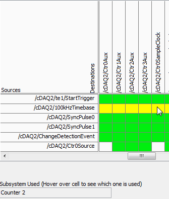
Specified route can not be satisfied, because it requires resources that are currently in use by another route.Source device: cDAQ1
Point source:
80MHzTimebase
Destination device: cDAQ1
Destination
Terminal: Ctr3SourceNeed for resources in use by Source
Feature: cDAQ1
Terminal of source: 100kHzTimebase
Destination
Feature: cDAQ1
Destination terminal: Ctr2SampleClockThe task name: _unnamedTask<61>
I don't know why this is, but if I start the PWM task first, and then the task of the encoder, it also works. I should also mention that initially I was using counter 0 encoder, which caused a shift in the 100kHzTimebase to Ctr0SampleClock, which, according to the ways of device 9411, is not supported. Yet it worked (in itself). I wonder if this is happening under the hood isn't quite what is shown.
What is exactly the conflict and what can do to avoid it? The reasons for having to use specific modes and the settings (for example, the 'continuous samples' with 100kHzTimebase clock) are rooted in various performance and requirements of optimization that were created in a previous version of our software, so I prefer not to take a completely different path, if some small changes would lead us to correct the problem.
I appreciate your help.
Kamen
Hi Kamen,
The time base of 100 kHz is not a direct route to the counter sample clocks, the device actually uses one of the other counters to complete the road (the routing table is a little misleading here because it shows 2 meter that one always doing road - in fact it will be any available counter):
So in your case, when you start the task of the encoder, it uses one of the other available counters to complete the configured road (100 kHz to ctr2 sample clock timebase). Of course, she chose meter 3.
Possible workarounds (looks like you have already found one yourself):
1 start the PWM before the task of the encoder task - if the task PWM starts first the counter is already booked and the task of the encoder would choose another available counter to complete its road.
2. explicitly reserve the PWM task before you begin the task of the encoder (if you need to start the task of the encoder first).
3. use cDAQ1/_freqout to generate the clock sample 100 kHz signal and use this instead of routing to the time base of 100 kHz to the counter sample clock.
Change autour counters should also work, but I'm not 100% sure how the unit selects which counter to use for routing (I don't expect change in the future, but if it's not explicitly spec'ed somewhere so I wouldn't take my chances)-if it were me, I would choose one of the other options above.
Best regards
-
Hi all
I played a bit with multisim for a few years now, but later began to really use the features of simulation of the program. I noticed that transient analysis of the very basic circuits seem to work fine, but nothing more than (especially those using pwm controls) after bogged down as some ridiculously short period of time. Also, before it freezes, things as the output of the oscilloscope function very slowly. I have attached my circuit for reference and using all that you wonderful people out there. What I am doing wrong?
The wizard of error correction is not really take care of the problem.
FYI, this is a converter circuit high power for which I would like to study the out performance characteristics by changing the frequency of the triangular wave or setting of the amplitude of the sine wave from 0 to 1. The goal is to produce a sinusoidal current output to the primary of the transformer. The resistance of inductance and conductor of leakage have been modelled, as well as an inductive load on the secondary of the transformer.
Thank you!
Yes, I tried for a few days and all the other typical timestep of bugs and it does not always work. The solution was to replace the igbt with the command switches in idealized voltage and barrier diodes schottky antiparallel... and on the ground of the transformer floating seconday. It works now
-
This is a homework problem Yes, I have summer through readings and I can't figure out how to do this.
We are able to use the temperature simulated in the activity file, I don't see where comes the thermometer and I want fills the degrees right now (F) to degrees (C). I know that the formula, but for the life of me I don't ' know how I plug it.
Suggestion 1. Always have the help context window open when programming. If the window is open and you move the tool of wiring on the cut wire, the Help window will tell you something about the cut wire. In this case it will tell you that the source is a scalar and the sink (graphic) requires a table.
The challenge will be to get your data into a table. I'll think about how to do
Suggestion 2. Index in array are integers. The point of coercion at the entrance to the index of the function Index Array tells you that LV is to convert one data type to another. In this case, you're probably OK, but you should still understand what stress and be able to explain its consequences. Better would be to use the appropriate data type.
Suggestion 3. The note inside the while loop mentions the call of a Subvi. It is also a clue on a way to deal with the problem addressed in the proposal 1.
Lynn
-
loop control and simulation: sync settings
Hello
Is it possible to access times higher at 1 kHz source in synchronization settings, control and Simulation in a loop, without use of real-time targets? For example, using time cpu.
I use myDAQ OR data acquisition, and I need a 100 kHz synchronization source about.
Thank you very much.
Kind regards
Keshav
N ° when running on a PC of the class, you are working with a set of standard material (with its clock 1 kHz) and a non-deterministic BONE, and there is nothing you can do about it. That is why acquisition cards NOR are all smart devices with their own processors, memory, and clocks.
Mike...
-
Possible sources of internal ArmStartTrigger to 6602
Hello
I use a card PCI-6602 in my application and I use all the input channels compared to 8 to count the edges of the PWM signals.
Everything works well except for one thing. It is essential that the counting of all 8 channels start at the same time.
I know that I should use the property 'ArmStartTrigger' of the respective channels to achieve. But I don't know what would be the best 'Source' for her.
As the measurement system is already on the client's site, it will be difficult to change/add hardware. That is, a single software solution is preferred.
The 6602 manual features: "relaxation of beginning of arm can be an internal or external signal.
What internal signals is available on the 6602?
Pouvez all this internal signal to solve my problem?
I know for example that a 6250 adapter can use "HERE/StartTrigger' as a command source to synchronize the analog input tasks with other duties. Is there something similar for the 6602?
Kind regards
Udo
The basic idea looks right. I can't guarantee calls DAQmx c# syntax because I have a boy of LabVIEW, strictly, but I don't see anything that looks like his place. I doubt that you need no waiting during the sequence and T - F time. The material of the Board will be triggering a transition edge and calls via the software driver to change the State digital each will take probably a few microsec or more.
-Kevin P
Maybe you are looking for
-
How to remove the new AutoComplete entries?
33 Firefox came with a new AutoComplete for forms. Unfortunately, I can't delete AutoComplete suggestions, once they have been preserved. It is a necessary feature for things like misspelled words, where you want to get rid of old (bad) semi-automati
-
Hotmail account not able to be cancelled
I have an account I tried to cancel three days. When I try to cancel it, he said that I charged paid account connected to it, so I go to the link provided to close, but I do not have. I tried to call microsoft to close and they are no help as they sa
-
I have a hp Pavilion dv 6000 series, windows vista home edition premium, the screen turned gray after I turned it on after the departure upward to boot... I really need help with this, I'm typing this on my macbook. Thank you.
-
Cannot print two-sided my HP750 of my MacBook pro
Help Please let me know how to print on my new 750 HP airprint on my MacBook pro
-
Problem with the Windows Installer Cleanup utility
I'm having a problem installing of a particular program, and told me to run the Windows Installer Cleanup utility. I downloaded msicuu2.exe and when I ran, got a Windows Script Host window: Script: C:\Users\AppData\Local\Temp\IXP000. TMP\StartMsi.vbs