Spice Netlist error
I try to model the DMMT3904W, double Diodes Inc. transistor. On simulation, I get this error:
-Checking SPICE netlist for designs 1 - Monday, June 27, 2011, 10:27:16 -
This is the model that I inserted: * src = DMMT3904W; DI_DMMT3904W; NPN BJT. If; 40.0V 0.200, 347 MHz Diodes Now, I can't know where the 'a' or 'A' comes! So... what I did wrong? Thank you... Steve Hello I was able to create the component for you. It is attached with this post. The symbol is just the generic box that you can modify in the properties-> value-> Edit in DB component and then going to the symbol. Read the template I created for this component. You need a subckt for these models. I hope this helps. Tags: NI Software Sparkgap model Spice ABM circuit netlist error message... Greetings, I'm having a problem with a Sparkgap modelling in Multisim 11... check the wiring diagram enclosed model ABM... Sparkgap_ABM. MS11 I use the Sparkgap_ABM model as a subcircuit a component in another circuit... see attached diagram... Coil Switcher.ms11 Rev limiter I created a Sparkgap_ABM circuit netlist... See attached the Spice subcircuit definition file... Sparkgap_ABM. CIR I used the SPICE Sparkgap_ABM.cir definition file to create the sparkgap component in the library of database user that I used in the Rev limiter coil circuit switch. When I run the simulation, I get the following error message... -Checking netlist SPICE to reel to the Rev limiter switch - Sunday 13 may 2012, 12:52:17 - It seems to be linked to the V1 voltage source that I use in the circuit of Sparkgap_ABM I put 0V to act as a current between the nodes pin 1 sensor and 3, it is referenced in an equation used by ABM V2 voltage source... I checked all the criteria of definition of SPICE for the use of a source of tension, ABM and I've changed the definition of V1 in just vV1 pin1 0V statement 3 statement of source V more complex as shown in the attached Sparkgpa_ABM.cir file. Doesn't seem to matter? Sparkgap model works very well in MicroCap 9 and I am trying to transfer the model to Multisim. I'm running out of ideas as to what could be the problem and I suspect it's something unique in the way that Multisim 11 addresses the definition of Spice files... I would appreciate suggestions from members of this forum as to what might be causing this error? Hi Nikv, I looked at your circuit of Sparkga_abm, and there are two problems. 1. in Multisim, if you want to use parameters in your equations, you must put in the arbitrary block of SPICE, the SPICE engine will not see your settings if you put text on the diagram. Take a look at the attached circuit to see how to add parameters to Multisim. 2. in the source of the ABM V2, the last part of the equation is: IF (ABS (I (V1)) > Isus, 10, 10n)), you must change the VV1 V1. In Multisim, when you place a source of current or voltage, Multisim automatically adds a V or I before the part is returned. If you select view > SPICE netlist Viewer, you can see circuit netlist as seen by the engine of the SPICE. Spice for model NDC7001C error Hello I get the following error when I run the simulation "SpiceModelSims" (attached). Could there be a problem in the spice itself model file? -Checking for SpiceModelSims SPICE netlist - Wednesday, March 21, 2012, 11:37:48 -
Thanks, any help would be appreciated! Hi Angela,. The model you used has two separate models, a P and a model N MOS. As you put the two models within a symbol, it will cause a problem of simulation. To resolve this problem, you must change the syntax so that two models of MOS are called in a single model, the syntax should look like this: .subckt NDC7001 DN GN SN DP GP SP . Copy your template after the top line .. .. .ends The attachment is the model with the changes I made. When you change your model, check out the tutorial of creation of component from the link below. Step 7 explains the relationship between the model subckt statement the symbol in Multisim. Many bogus netlist MS/UB 11 errors are produced Hello I'm all kinds of false netlist errors in UB11. It is not the problem here: http://forums.NI.com/NI/attachments/NI/370/7315/1/missing%20PIN%20from%20Net%20error.doc Is missing pins that do not yet exist on the track that is pin 11 to a size of 10 pin or pins which are actually missing. He seems to think that some pine shouuld be connected to two different networks. What is going on? DRC error report is attached. The first suggestion might work, but a real pain as mentioned. The second not because the party in question does not appear in the file exported from BA. Here is the best solution (except NEITHER solved the bug): Import of a SPICE Supetex model - questions Hello I have a. File MOD of Supertex for one of their MOSFETs. I tried to import the component in to multisum the "component" Wizard of multisim, but I always got the error... -Checking SPICE netlist for designs 1 - 4 June 2013, 15:53:44 - Why multisim don't care what model? And how can I change to solve the problems? The model, which was provided to the East: . SUBCKT TN6420 1 2 3 Thanks for any help in advance Rob It seems that this subcircuit, written for a specific in mind Simulator, attempts to use the BSIM3.2 mosfet model. We have BSIM3.3 = 8 level. Simply change the value of the parameter level of 8. Here is a table of our help documentation: Modeling and Simulation occur error I have established a model APEX PA78, but the simulation reports any error, please help me! View report worksheet is followed: -Audit netlist SPICE to PA78 - 2010-01-28 20:12- Error of SPICE Netlist in schematic RefDes 'u2', '
Error of SPICE Netlist in schematic RefDes "u1", item 'xu1': unexpected '1' found subckt - too many nodes or missing name value parameter instance online. Error of SPICE Netlist in schematic RefDes "u1", "
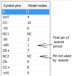
= SPICE Netlist verification completed, 4 error (s), 0 warning (s) =. --------------------------------------------------------------------------------------------------- The accessory includes three files, they are: PA78. TXT is the BERKELEY SPICE on PA78 model of http://Apex.Cirrus.com/en/products/Apex/design_software.html PA78U_B.PDF of page on PA78 of http://Apex.Cirrus.com/en/products/Pro/detail/P1163.html PA78. MS10 is a configuration of bridge-connected, but PA78 itself do not work a simulation. Hello I'll expand a bit what Angela said on the. ENDS and then try to clear up the pins. The SPICE model that you use for the PA78 includes several subcircuits and models. Best practices for creating a component in Multisim are having one. SUBCKT or. MODEL for each component. The point of this is to ensure that the additional models or models contained so that they do not interfere with each other in the final netlist. The best way to solve this problem is to move the. ENDS during the main subcircuit until the end of the complete draft - so, instead of simply add the. ENDS at the end, you must also remove the first. END of line in the file. For this circuit, you probably don't need to do it, however in general, it's a good idea to do by making a component like this. With respect to the pins, step 6 of the component wizard asking you order the pins will be used in the model. The (original) model that you have only 10 knots, so it isn't a problem if you have only 10 pins there. If you have 12 pins on your symbol, and only 10 model nodes, then you score just two unused pins as "NC"(vous pouvez également ajouter deux broches"fausses"pour le.) ". SUBCKT which is what you did, but you have not). For the rest of the pins, see the. SUBCKT line and comments just ahead of him: Comments indicating the order of broaching tell you the order in which the terminals must be indicated when you use the PA78. SUBCKT. As you can see on the. Line SUBCKT and comments, even if IT is pin 1 on the component, it should actually be listed third when you use the. SUBCKT. It's asking you to step 6 in the component wizard. Step 6 allows you to specify the order in which to use the pins to Multisim. The comment you indicates that + is the model node 1, - IN is model node 2, IT is the model node 3, etc., and then you say Multisim by setting the number of nodes of model Hope that helps! Apex PA50 SPICE model used in Multisim Below, I pasted the code of the Apex SPICE for their PA50 power amp. I tried to use the Wizard component in Multisim, but when I run the simulation I get the following errors: 1st a popup) an error was found in the Netlist, would you like to continue nevertheless? 2nd if I proceed)-netlist SPICE checking to Apex_PA50 - Saturday, July 20, 2013, 12:54:12 -
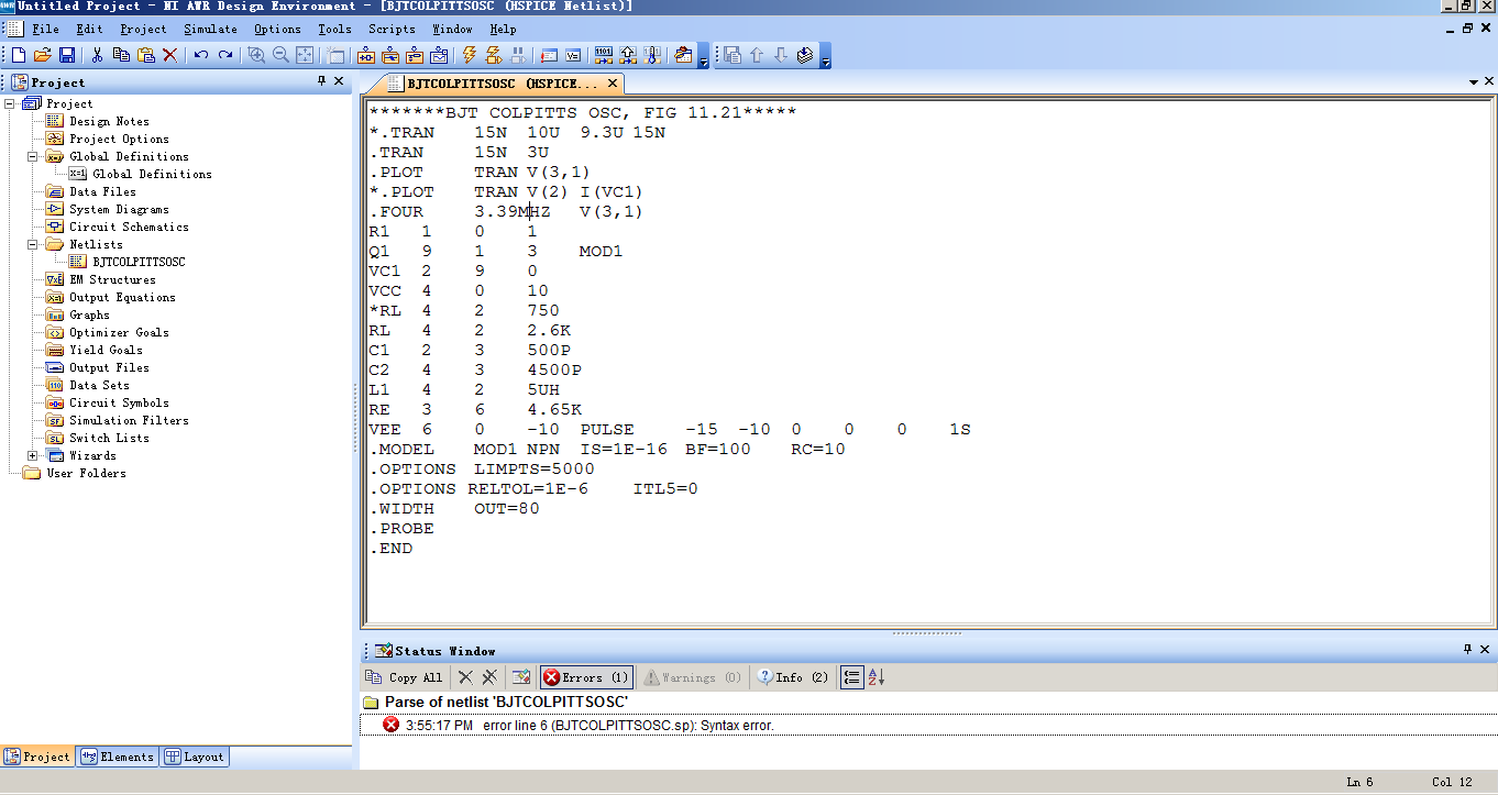
You SPICE gurus out there knows how I can get these kinds of patterns Apex in multisim? They are really big amplifiers. Thank you Robert Harker *********** * REVISION 2 MARCH 18, 2002 * REDUCTION OF INTERACTION OF THE SLEW RATE WITH CHANGE IN DIET. * START OPAMP MACROECONOMIC PA50 * STITCHING ORDER IN - IN + OUT + VB - VB + VS - VS . SUBCKT 1 2 3 4 5 36 37 PA50 10 1 8 JI1 J1 11 2 9 JI2 J2 12-8 1.34E + 03 R3 12 9 1.34E + 03 R4 I2 5 12 4.50E - 04 5 12 5.00E C1 - 13 5 12 + 06 5.45E R5 10 4 1.59E + 03 R1 4 1.59E + 03 11 R2 10 11 1.67E C2 - 11 4 5 2.64E I1 - 02 G1 6 15 11 10 6.28E - 04 G2 6 15 12 15 2.81E - 08 6-15 1.00E + 05 R6 6 15 DD D1 15 6 DD D2 6 7 7.50E C3 - 12 15 7 15 6 + 01 1.00E G3 7 15 1E3 R7 16 7 DD D3 18 16 + 00 5.50E V1 7 17 DD D4 17 19 5.50E + 00 V2 RE1 15 0 0.001 38 0 4 0 1 E2 39 0 5 0 1 E3 R8 7 20 50 20 15 5.80E C4 - 11 37 20 21 QOP T3 36 20 22 QO'QON T4 36 21 29 QO'QON Q5 37 22 29 QOP Q6 41 36 38 36 0.69 E4 42 37 39 37 0.69 E5 18 0 41 0 1 E6 19 0 42 0 1 E7 RY1 38 0 10E6 RY2 39 0 10E6 RY3 41 0 10E6 RY4 42 0 10E6 I3 36 21 5.36E - 03 I4 22 37 5.36E - 03 I5 37 36 1.0E - 02 29 3 8 R15, 5TH-02 29 36 DC1 DO 37 29 DC2 IS . MODEL D (CJO = 10PF IS = 1.26E - 12 RS = 2.38E - 03) . MODEL D DD (CJO = 0.1PF IS = 1E-17) . MODEL DL D (CJO = 3PF IS = 1E-13) . MODEL JI1 NJF (BETA = 4.00E - 03 EAST = VTO 3RD-16 = - 1). . MODEL JI2 NJF (BETA = 4.00E - 03 EAST = VTO 3RD-16 =-1,0050) . MODEL QOP PNP (BF = 2.35E + 04 IS = 1E-14) . MODEL QO'QON NPN (BF = 2.35E + 04 IS = 1E-14) . MODEL RLQ NPN (BF = 100 IS = 1E-14) . MODEL SPCA PNP (BF = 100 IS = 1E-14) * END OF OPAMP MACROECONOMIC . ENDS ************ I haven't studied your ad but clearly the xU1 call isn't in a SPICE compatible format. The definition of subcircuit PA50 has 7 knots. Your call xU1 has 12! Nodes U1_OPEN_11 and U1_OPEN_12 exist anywhere else in the document. Lynn Invalid subckt definition name I downloaded the LM35 by Patrick of the forum example OR. I faked it and it works fine. An excellent example of a temperature sensor, incidentally. Quick salvation, I think the problem is that you have created a name with a space in the name (SENSOR of TEMPERATURE). If you rename the family in order to remove the space and then replace the component in your schema, it must simulate correctly. My best guess is that you have space in the family name by pasting "SENSOR of TEMPERATURE" in the family name dialog box. I have found some problems our manager of incidents so that we can solve this problem in a future release (D116840 and D116841). However, if you have the space in the name of another way, let me know if I can add that information to bug. I composed a few diodes the wizard of components, such as the diode acts like a switch perfect to 0.7 volts. For some reason any SPICE simulation does not run. If I include one of these diodes in other circuits, the circuit will not simulate. The diode model is the problem. Any ideas how to operate? Attached is the file multisim Thanks in advance! "- Checking SPICE netlist for perfectbridge - Thursday, February 5, 2015, 11:51:34-" So: right-click on one of the diodes, select 'Properties' - 'Value' tab - press "Change model" button - box 'Use default' for 'IS' - press "Change all 4 elements" - press "OK". I have a problem to put a different voltage to my SPICE2G6 model and get different ability of a varactor diode what should I do? Please find attached the SPICE model, I need analysis with AWR. You can try to import spice model, but I recommend place you a model LIDS in a pattern and double click to edit the settings, and then click on "post secondary" to list all the parameters. Find 10 settings or if in your spice netlist and enter these values. I think this is going to be the most straightforward approach because it is has only a few parameters to be defined. How to model generic spices work in multisim? I have a model external Spice, I need to use occasionally. I alsways have trouble with that. It doesn't seem to be because I don't understand the models or how operation spices, but more than the conventions to set and get properly hanging nodes and other aspects of MS are ambiguous to me. This is a model of NTC thermistor and a multisim schematic, I'm working on. I tried many things but you do not have the errors go away. I put back the way I started here. This model is: http://www.ecircuitcenter.com/circuits/therm_model1/therm_model1.htm Can someone explain how to get this model of thermistor NTC to work in MS? The ramp from 100V to 1V/s source matches the entry of temperature to the model. (0-100 C, 1 ° c/sec on the grapher, if I ever get there) Thank you David B Hi David, I think that you pasted the netlist any data on the Web page in the Multisim Components Wizard. I think that it is the root of the problem. You just enter in the wizard components are really, the following lines: The remaining lines that are given to you generate the stimulus, as the voltage source that you placed in your schema. I have corrected it and attached the circuit has been fixed. Open this in Multisim and simulate a click > analysis > DC Sweep and click on simulation. You should see the curve IV of resistance NTC operating at different temperatures. Hope that helps. How to import the hspice netlist? I'm starting to learn how to import maps hspice. I want to understand what is the difference between Hspice and AWR for RF circuits and devices, I have a question on how to import maps. I followed the instructions to import an existing hspice file. but it does not work. I could not simulate. The status window displays syntax error on line 6 that gives me the warning below. But I can simulate it by using Hpsice. There is no problem at all. So I'm so confused. Can someone tell me what I need to do? Thank you very much in advance. Hello You cannot import raw Hspice netlist. Many lines of these files are files of control for the execution of the simulation. What you need to do is to put the part of the circuit of the netlist in one. SUBCKT command you can see in the example of "Exposing_and_Tuning_HSPICE_netlist_model_parameters.emp." You will not be able to simulate due to licensing, but you can see the structure that must be the netlist. Then you instantiate this netlist in a schematic representation and add sources, you can analyze the circuit. I hope that you get. Support of the AWR Hello I would like to convert spindle IBIS models to patterns of behavior SPICE I can import in multisim. I then combine these models of PIN with others built in components to make a simulation of end to end. I tried the free converter of Intusoft and get several errors when I import the SPICE circuit in a new component. My question to the group is, does anyone know of an IBIS in the converter of SPICE (free of preference, but ready to buy something if necessary) that generates a code that can be imported directly into a component of multisim with no editing? I guess that I would accept a small change, but I have several pins to bring and don't want to risk screwing the underlying model -Steve Hi Steve,. There is no particular way to IBIS spice that is recommended for work in Multisim. I think that if there is no chance of finding that the Spice model would be the best option. There are some other forums with more information on IBIS to spice. It seems that thay use the same tool that you have. Kind regards Import the SPICE model for transistor BJT BFP720F in Multisim Hello I'm trying to get the SPICE model for the BFP720F transistor provided by Infineon to work in Multisim. I have attached the template as provided by the manufacturer. If I import it as-is, I get error messages "invalid node identifier '<4>'" (I have translated that German, it might not be exactly this message in the English version).
So I tried to replace all the "<4>" with "4", which seems to help, but now the error is "adjusted temperature setting"VJC (PC)"negative" and "incorrect use of the parameters of the model. Now I don't really know what to do with it.
Is the template provided in the wrong format? I somehow can it in the right so I am able to use it? Because I need for my project semester in College, any help would be much appreciated. Thanks in advance! Hi NikoNR, When writing a detailed description of what I did exactly with the Wizard component, the component again to create in Multisim from scratch, I found that there are different SPICE models provided in the package for use with AWR MWO. They have a different file extension, but are normal text SPICE inside files. It turns out that they actually work with Multisim. The difference is small, there is only one temperature (TNOM) setting that is absent in these models, distinct from the "general" I first tried to use. It seems that Multisim had a problem with this setting, leading to the error I encountered. Anyway, the problem is solved now. Thanks for your help Good day (The now much happier) EE-student ---- Edit: I have attached the SPICE model, that I ended up using, in case someone at - he never met a similar problem. The only change I did this, is to replace '<4>' with '4' in the part of the diode (single occurrence here). I had to zip to download with his original extention (.mdl). Problem with the Spice TI OPA140 model I edited the attached spice model to fix the missing parenthesis, but when I try to create a symbol linked to the model I get an error "this template contains several top-level. SUBCKT statements... ». I tried the present models in the model of main circuit of nesting, but I can not get an accurate simulation (transitional works, AC Sweep is weird). How a spice must model with multiple. SUBCKT statements be managed in Multisim? Thank you Tim KB2572067 update has not been installed. Get the message the following updates have not been installed. The update of security for Microsoft .NET Framework 1.1. SP 1 in Windows XP, Windows Vista & Windows Server 2008 x 86 (KB2572067). I am running windows XP and have updates set to automa Disable the startup of the Volume control in the system icon tray. I need to disable volume control start in the system tray so that it does not show users that connect. So far, I've fiddled with regedit, msconfig and mmc. I can turn it off for my own login, but when others open a session, it appears. Note: the vol Problems with UAC, Sims 3 downloader and original windows Problems with UAC, Sims 3 downloader and original windows I have windows Vista and have been using it for a while to play the sims 3 and download games via original EA downloader/store. I had run a windows update and an original updated in the last How can I add a filter on my Web site, which displays results immediately on the same page? Hoe kan ik een filter toevoegen op mijn site, results old weer geeft die in of zelfde pagina? The AMD GPU of 390 R9 is compatible with Adobe first Pro CC? Hi allI want to buy a new video card. The AMD R9 390 is one I want. This model does not appear in the list of requirements (system requirements:) Adobe Premiere Pro). In my view, because the list has not been updated. Does anyone know if this card wi
Error of SPICE Netlist in schematic RefDes "u1", item "1": model "npn" type is not allowed for components with the letter of the prefix 'A '.
Error of SPICE Netlist in schematic RefDes "u1", "
= SPICE Netlist verification completed, 2 error (s), 0 warning (s) =.
Inc. correspondence of Transistor
. MODEL DI_DMMT3904W NPN (IS = 20.3.f NF = BF = 274 VAF = 114 1.00
+ ISP = 36.4 m ISE = 6,99 p DON'T = BR = NR = 1.00 4.00 2.00
+ VAR = 24.0 IKR = 90.0 m RE = 0.657 RB = RC = 0.263 2.63
+ XTB = 1.5 NCE = 8.29 p WILL = 1.10 JEM = CJC = VJC 7.10 p = 0.300 0.500
+ MJC = 0.300 TF = 426, p b = 71.3n EG = 1.12)Similar Questions
Error of SPICE Netlist in RefDes schematic "v2", "bv2" element: "v1" referenced in the expression element does not exist in the local scope or is not of a type that is compatible with the function I()
= SPICE Netlist verification completed, 1 error (s), 0 warning (s) =.
Simulation error message: bv2:xx1: unknown source v1 control
Simulation error: doAnalyses: no such settings on this unit
Simulation error message: tran simulation (s) cancelled
Error of SPICE Netlist in schematic RefDes 'u3' element 'xu3': unexpected '0' found subckt - too many nodes or missing name value parameter instance online.
Error of SPICE Netlist in schematic RefDes 'u3' element '
= SPICE Netlist verification completed, 2 error (s), 0 warning (s) =.
XQN DN GN SN SN NDC7001CQ1
XQP DP GP SP SP NDC7001CQ2
netlist Editor (Tools > editor of Netlist). It is a comprehensive
research and would take a long time if you have a large design.
you know the name of the faulty nets and components, export of the
netlist to a file (transfer > back annotate to Multisim > return)
annotate the file), open it in your favorite text editor and look for
the offending items.
Worked very well. If the part you place didn't have enough pins for one of them to be the offending pin number, you won't see the bad connection.
Error of SPICE Netlist in schematic RefDes 'u2', 'mosmod' element: unsupported type of model 'PMOS.
Error of SPICE Netlist in schematic RefDes 'u2', 'm1' element: type of device unsupported SPICE "MOS7."
= SPICE Netlist verification completed, 2 error (s), 0 warning (s) =.
11 2 3 3 M1
+ MOSMOD
+ L = 3E-06
+ W = 0.058
+ AD = GRADES 9-12
+ PD = 1.2E - 05
+ AS = GRADES 9-12
+ PS = 1.2E - 05
JMOD JFET 1 3 11 1
* AREA = 1
3 1 led 1 Cbody
* A = 1
1 11 Rdummy 1E + 06
. MODEL JMOD NJF
+ = - 10 vto
+ beta = 0.03864
+ is = 1E-15
+ = 3.281 rd
+ lambda = 0
. Diode MODEL D
+ is = 1E-15
-n = 1
+ r = 1
+ bv = 250
+ ibv = 0.001
+ tt = 1E-06
+ cjo = 8-11
+ vj = 0.6
+ m = 0.5
. Model MOSMOD NMOS
+ = level 7
+ version = 3.2
+ paramchk = 1
+ mobmod = 3
+ capmod = 3
+ noimod = 1
+ delta = 0.01
+ tnom = 27
+ tox = 7, 5th-08
+ toxm = 7, 5th-08
+ 7.739E = + 16 nch
+ xj = 5th-06
+ vth0 = 1.1
+ k1 = 0
+ k2 = 0
+ k3 = 11.69
+ k3b =-22.99
+ w0 = 0.0001
+ nlx = 0
+ dvt0 = 2.2
+ dvt1 = 0.53
+ dvt2 = 0.05058
+ dvt0w = 0
+ dvt1w = 5.3E + 06
+ dvt2w =-0.032
+ eta0 = 0
+ features = 1581
+ d Sub = 0.56
+ u0 = 261.1
+ au = 1E-10
+ ub = 1E-20
+ uc = - 1-09
+ = 1.778E + 04 vsat
+ a0 = 0
+ ags = - 1
+ b0 = 0
+ b1 = 0
+ = 0.136 keta
+ a1 = 0
+ a2 = 3.414
+ rdsw = 3.273E + 04
+ prwb = 0.3214
+ GTRP = - 10
+ wr = 1
+ wint = 0
+ wl = 0
+ RFD = 1
+ ww = 0
+ wwn = 1
+ wwl = 0
+ dwg = 0
+ dwb = 0
+ Toys = 0
+ He's = 0
+ lln = 1
+ lw = 0
+ lwn = 1
+ waterline length = 0
+ = 0.0157 voff
+ nfactor = 0.7
+ cit = 0
+ cdsc = 0
+ cdscb = 0
+ cdscd = 0
+ cffp = 0,1
+ pdiblc1 = 0
+ pdiblc2 = 1E-06
+ pdiblcb = 1
+ drout = 0
+ pscbe1 = 3.548E + 08
+ pscbe2 = 1E-09
+ pvag = 1E-06
+ alpha0 = 0
+ alpha1 = 0.04694
+ beta0 = 210,8
+ js = 5-10
+ jsw = 0
+ nj = 1
+ ijth = 0,1
+ cj = 0
+ mj = 0.2387
+ pb = 0.3
+ cjsw = 0
+ mjsw = 0.33
+ pbsw = 0.3
+ cjswg = 0
+ mjswg = 0.33
+ pbswg = 1
+ cgbo = 0
+ cgdo = 0
+ CASE = 0
+ cgsl = 4.5E - 09
+ cgdl = 2.8e - 09
+ Shorty = 0.6
+ cf = 0
+ noff = 1
+ voffcv = 0
+ cela = 1
+ less = 15
+ dlc = 0
+ = dwc - 3.584E - 08
+ llc = 0
+ lwc = 0
+ lwlc = 0
+ wlc = 0
+ CME = 0
+ wwlc = 0
+ clc = 1E-07
+ key = 0.6
+ Elm = 2
+ xpart = 0.6
+ kt1 = - 0.11
+ kt1l = 0
+ = 0.022 kt2
+ ute = - 1.5
+ ua1 = 4.31E - 09
+ ub1 = - 7.61E - 18
+ uc1 = - 5.6E - 11
+ a = 3.3e + 04
+ prt = 0
+ xti = 3
+ tpb = 0
+ tpbsw = 0
+ tpbswg = 0
+ JCT = 0
+ tcjsw = 0
+ tcjswg = 0
+ af = 1.5
+ ef = 1.5
+ kf = 1E-17
+ Ms = 4.1E + 07
+ noia = 2nd + 29
+ noib = 5th + 04
+ site = - 1.4E - 12
. ENDS
Error of SPICE Netlist in schematic RefDes 'u2', item 'xu2': unexpected '15' found subckt - too many nodes or missing name value parameter instance online.
* PINOUT ORDER +IN -IN IL OUT +VS -VS CR+ CC+ CR- CC-* PINOUT ORDER 7 6 1 2 12 4 8 11 10 3.SUBCKT PA78 7 6 1 2 12 4 8 11 10 3
Error of SPICE Netlist in schematic RefDes "u1", item 'xu1': unexpected '6' found subckt - too many nodes or missing name value parameter instance online.
Error of SPICE Netlist in schematic RefDes "u1", "
= SPICE Netlist verification completed, 2 error (s), 0 warning (s) =.
I saved the LM35 component to my database. Then I inserted into my diagram.
When I try to simulate, I get this error:
-Audit netlist SPICE to TempCFan3 - 2010-01-18 13:10:12-
Error of SPICE Netlist in schematic RefDes "u1", item 'xu1': name of the definition subckt invalid "sensor__2".
Error of SPICE Netlist in schematic RefDes "u1", "
= SPICE Netlist verification completed, 2 error (s), 0 warning (s) =.
I watched the news on the model, but don't see any reference to "sensor__2".
= SPICE Netlist verification completed, 0 error (s), 0 warning (s) =.
Model 'diodeperfect__perfectdiodes__1': 'IS' parameter must be greater than zero
doAnalyses: incorrect use of the parameters of the model
Cancelled simulation. ". SUBCKT NTC_10K_1 1 2 4 5
ETHERM 1-3 VALUE = {I (VSENSE) * 10 K * EXP (3548 / (V (4,5) + 273) - 3548 /(25+273))}
VSENSE 3 2 DC 0
. ENDS
Maybe you are looking for