Table 2D FFT spectrum
Hi all
I'm doing the analysis of the spectrum of a 2D array. In this case is Amplitude (Y) depth (X) vs. The problem is that the depth (X) is not a constant dt so I can't create a normal waveform as an input for the power spectrum analyzer or spectral measures vi.
It is an example of some of the data that we have:
Depth range (x) (y)
| 8390.7 | -15.767 |
| 8391.2 | 15.767 |
| 8391.7 | 6.8555 |
| 8392.2 | -6.8555 |
| 8392.7 | 25.754 |
| 8393.2 | -25.754 |
| 8393.7 | 2.8505 |
| 8394.2 | -2.8505 |
| 8394.7 | -8.574 |
| 8395.2 | 8.574 |
| 8395.7 | -16.145 |
| 8396.2 | 16.145 |
| 8396.7 | -0.063 |
| 8397.2 | 0.063 |
| 8397.7 | 3.3945 |
| 8398.2 | -3.3945 |
| 8398.7 | 7.712 |
| 8399.2 | -7.712 |
| 8399.7 | -6.267 |
Thanks for any help
Tags: NI Software
Similar Questions
-
Standardization of FFT spectrum
Dear Sir
I take FFT of my real-time data that I collect current probe. I get the FFT spectrum successfully. But my supervisor asked me to normalize the present 25 Hz harmonic component in the FFT spectrum with fundamental component. Can you please guide me how to do this task.
Also, what is the standards and what are its advantages.
The frequency of the fundamental component is 50 Hz.
Your attention and consideration will be highly appreciated.
Kind regards
Urfee
-
Why the FFT spectrum gives values of RMS?
Dear Sir
I want to get the value of crete to crete on FFT spectrum. But he gives values of RMS. Can you please guide me how can we peak to peak on the FFT spectrum. Attach the vi is for example.
Kind regards
Urfee
Tronoh wrote:
Dear Sir
I want to get the value of crete to crete on FFT spectrum. But he gives values of RMS. Can you please guide me how can we peak to peak on the FFT spectrum. Attach the vi is for example.
Kind regards
Urfee
What does it mean to get the value of Ridge Crest of a FFT spectrum? [I understand getting the value of P - P of the signal ...]. Note that the parameters on the average you attached (which shows mean quadratic value, by the way) refers to the way in which the Spectra will be averagedand RMS is logical (logical) in many cases, but I'm at a loss to understand the average peak-to-peak here...
BS
-
Weighting of exponential power FFT spectrum mode
In the spectrum power of FFT VI mode exponential weighting from the link:
Weighting is applied according to the following equation.
where Xi is the result of the analysis conducted on the ith block, Yi is the result of the average of X 1 XI, N = i for the linear weighting, and N is a constant for the exponential weighting (N = 1 to i = 1).
For the exponential weighting, N is a constant. What is its value?
Yes, but N = I do not mean that it is constant. For weighted linear N = i means N = 1 when I = 1, N = 2 when I = 2... And on average stops when I reached your set number.
For the exponential weighting N is constant (the number that you define) that leads to an exponential weighting. The average never stops in this case.
-
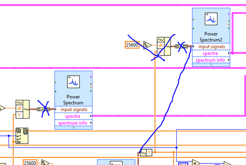
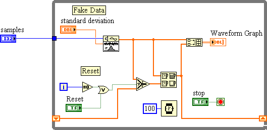
Hi, I can't manage with table 2d FFT. I convert the data from excel. In labview, it is a 2 columns with array of 10000 lines. Then I traced chart XY in this table (using "build the graph XY") and it is well marked. Now I need to use FFT on this and I really can't understand it. When I use the spectral measures it shows something like one noise, or other random * beep *. How my VI looks like is attached below. Sorry for my English
I added a power spectrum in your VI. The result looks like what you would expect.
See you soon
Edgar
-
power output of the spectrum in table
Hello
I have a signal and I need to make the power spectrum. How can we separate the information contained in the output of the power spectrum cluster? I tried to use the unbundle, but it gives me an error: "the type of the source is table 1 d of the cluster of 3 elements. The sink type is cluster of items 0 "if I click on the unbundle it won't let me select anything, it says empty..." Does anyone have an idea how to solve this, please?
Array of generation is not your friend here actually I replace the generation arrary and the screw Express Power Spectum with 'FFT Power Spectrum and PSD.vi' search the palette or use quick drop to locate him.
Why shoot there since just filtered signal to rebuild the same waveform? Wire the waveform to the second power of DSP and FFT spectrum .vi directly

-
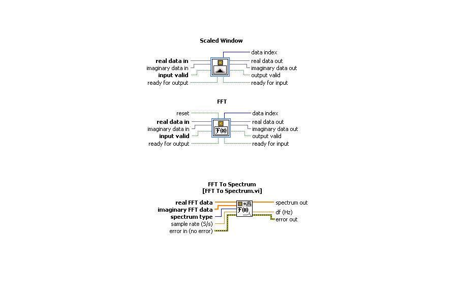
Using FFT to palette spectrum Subvi Interface of FPGA functions
Hello
I use the card PCI-5640R and PXI-5600. I want to use the "scale" and "FFT" exspress screws to the range of functions 'Mathematical FPGA and analysis' in my VI "FPGA VI" and "FFT spectrum for '"FPGA interface"in my"host VI.
A poster of the code examples in which these three subVIs are used can.
Thanks in advance.
Kind regards
Rashid
Hi rachid,.
There are two examples of delivery here: LabVIEW 2009\examples\R Series\FPGA Fundamentals\Analysis and Control\FFT\
Jim
-
Creation of 1 d-Array permanently FFT
Hey guys,.
Im making measurements of vibrations with an accelerometer on my mydaq. I already get my timesignal reading properly. Subsequently, I record these readings in a 1 d table. Now, I want to achieve a FFT spectrum.
But the illustrious FFT's are useless, they do not display something useful. I tried before to take a FFT is the express.vi and it worked perfectly. Has obtained Spectra as normally and worked well. But as Im not allowed to use the s express.vi in my project I can't use it.
So, any help would be very appreciated Im getting nuts with him and Im trying to get this race for 3 days...Thank you very much
LabView 2014
Configure the Read DAQmx for samples of N. reglez_ to return a data type of waveform. Connect to your fft function.
-
Output power of the frequency spectrum
Hello
I have a pretty simple question. I m using the power spectrum of FFT and PSD vi. and have trouble understand output frequencies. If I understand the first line is DC-value and delta frequency then describe the following frequencies. But when I put for example in 8 points say sampling frequency of 4 Hz = 2 seconds of data to analyze, I'll be back 4 lines of data (including 0). If the first is DC, then the 2nd should be 1 / 2 Hz 1 Hz = 3rd place and 4th place = 3 / 2 Hz, but what about the frequency of 2 Hz Nyquist, why Don t I get this one? or is there something I don't understand?
I also tried the example of Units.vi of FFT spectrum and can understand, but I still Don t get it.
Help, please!
Best
Jesper
FFT returns to power in frequency bins. The frequency of the bins is determined by the Fs (sampling frequency) divided by N (number of points), from DC (0Hz). For your case, the table returned would be:
Bin 0: 0-0.5 Hz
Bin 1: 0, 5 - 1 Hz
Tray 2: 1-1.5 Hz
Bin 3: 1.5 - 2 Hz
So effectively Bin 3 holds the power of 1.5 to 2 Hz (which contains your Nyquist frequency).
-
I'm figuring the FFT of several signals, I have used sine waves in the attached vi to highlight my problem.
I created 3 sinusoidal signals using signal generated express vi.
Sinusoidal signal 1: Fs = 20 Hz
Sine wave 2: Fs = 250 Hz
Sine wave 3: Fs = 500 Hz
I combined these signals in a table and fed in FFT Soectrum (Mag Phase) VI and see the results on a graph in the form of wave. I changed the property of multiplier of charts to the sampling frequency of the singal handset (1 sine wave Sine Wave 2 + Sine Wave 3) which is equal to 770Hz.
The plot of the FFT spectrum is throw up quite unexpected results. I expected peaks at 20 Hz, 250 Hz and 500 Hz, but I get crazy values.
I'm doing something wrong... ? Take a look at the vi attached please.
Stroke
Hi the shots.
You seem to be missing a few basics about LabVIEW data types as well as their manipulation...
You cannot add waveforms by adding berries to Y in a larger painting, you must Add the.
Play with the filter command in the attachment (to perform a control of it can make it easier...)
-
FFT waveform (file converted from Matt file lvm) - how to overcome the error dt < = 0?
Hello
I use a lvm file after conversion of Matt file. I wanted to get the fft spectrum. I get this error message this dt waveform<>
How he overcome?
I have attached the matte file and the vi that I used.
Best regards
FESMI
The Forum is a bit special files that can be attached. Creating a zip file often works. Sometimes, you can change the .txt extension. If you change the extension, please indicate in your message which was the extension of the moose.
It seems that data in the file has a time column and a column of amplitude. The LabVIEW waveform data type is a cluster of a table of amplitudes (Y), sampling interval (dt), from the time (t0) and optional attributes. That's what the power spectrum VI requires as input. The t0 values is not used if the default is fine. the value of dt can be calculated by the difference of the two adjacent values in the time column. Given that the first value is equal to zero, the second value is equal to dt. Use the primitive to build a waveform of the palette of waveform. Expand it to view the dt element.
In the VI attached all lines is an indicator that contains your saved default file data. Graph XY plots that data. After subtracting the way to get rid of a continuous component, the data is converted to a waveform. The power spectrum is calculated and displayed using the same VI as in your program. It also uses extract several Information.vi tone for the frequency and amplitude of the main peaks in the data.
Interestingly, the lower frequency of the spectrum a harmonic of 60 Hz while the tops are almost sharp space 4 kHz ~ 100 Hz apart. The broad peak near 2.1 kHz does not seem to have noticeable components to 60 or 100 Hz.
How to avoid the Type of dynamic data (DDT)? Stop using screw Express! For reasons known only to EITHER screw Express a deliver their outputs via the DDT. Except when you open the block diagram of the express VI, there is no way of knowing what the underlying data structure on a thread of DDT.
Lynn
-
The FFT LabVIEW uses the usual term of eponential:
e ^ (-i * 2 * pi * k * n/N)
Is it possible that I could change this term to include a constant and perform the FFT as usual? that is to replace the exponential term above with something including a constant 'c ':
e ^ (-i * 2 * pi * k * n * c/N)
I actually use a 2D on a square table 2D FFT, but hopefully a solution to the case 1 d above would be easy to apply.
If it's more math than the programming problem, a point in the right direction would be always greatly appreciated!
The only parameter that you can control is N, the number of samples in the dataset. You can try to do 1/N ' = c/n. See if this will give you the results you expect. If c < 1,="" then="" n'=""> N and fill the input data will be required. For otherwise, a reduced supply is necessary. Pay attention to how the data is compressed so that you don't miss any information.
Lynn
-
Hello
I would like to compare the values of one signal (table 1 d) with each other and then displays the maximum value. But only if desired.
It should be in principle, a peak hold function, I always displays the maximum value.
In the "power FFT Spectrum.vi", there is such a "ridges". However, I don't know how I can integrate it without the "FFT Power Spectrum.vi' in my vi.
Maybe someone can help me here.A picture of the vi says maybe more (the picture shows a first attempt, which unfortunately does not work as expected).
Thank you and best regards
Alesis
All you need is a little help from Max & Min function (at least for the way I remember Max Hold)
-
Save all the data for a while loop
I already asked a similar question, but it is perhaps not very clear, and there are a few concepts that I did not understand.
1. I have a keyboard to generate flow DTMF signal (I call it stream because it contains several shades that consist of a full phone number)
2. I would like to save it as a wav file, but I guess that another format is correct and because the writing on a wav file does not support add so for this particular case, I use writing waving instead of writing to wav format
My approach is to have a structure of queue so that I can write each iteration results in a file.
(i) when I try to retrieve the data, there's nothing but 0.
(II) my intention is to get 8000 samples per second (fs = 8 000) but he back up data so fast
I have attached the file so if there is a way to solve problems, please help me.
This vi includes many elements discussed above. There are no provisions for the intervals 'no signal '.
Changes: Replaced with native features of LabVIEW Mathscript node. Mechanical Action to latch release button. Cluster to array replaces Unbundle and table to build. Reshape the table to match the shape of the keyboard. Separate searches for frequencies of line and column. Note that this is easily extensible to handle the 4 x 4 keyboard. Structure of the event added. Added the stop command (but not implemented stop to the loop of the file). Added indicators for diagnostic purposes. Added FFT spectrum and graphic.
I disabled writing to part of the file for testing.
Lynn
-
Hey,.
I did a little code that allows to calculate the bandwidth of an FFT spectrum, but I need some improvements of this caluclation.
what I did is:
1. I calculated the FFT of the time signal.
2 - I calculated the maximum of the FFT spectrum and divided it by 2 to get the max of half.
3 i made a linear interpolation using the equation (x = x 0 + ((x1-x0) *(y-y0)) / (y1 - y0)) and used half max. as input for y.
4. I used the legend of cursor to determine the 2 points (x 0, y0), (x 1, y1) necessary for linear interpolation and then I wrote these point values in the controls 'Bandwidth calculation' to find x, which is the bandwidth.
is it maybe better to calculate? I want to say how can I change the code so that I can find the bandwidth automatically without the need to give the values of these 2 points?
Thank you
Here is my code...
As the first point is greater than half of max, I'm not sure how significant the calculation is.
A way to find the max half point is to use the threshold function of table 1 d. It only works on arrays with increasing values, then to find the falling threshold, subtract the table of the peak value.
I have attached an amendment to your VI to show a way to do this. I also showed how the calculation can be done with the primitives of LV math rather than the node of the formula.
Lynn
Maybe you are looking for
-
can not connect to ebay, all other sites are ok. Can I access with my ipad
I tried your last solution, but it did not work This problem may be caused by corrupted cookies or cookies that are blocked. check the permissions on the about:permissions page and in "Tools > Page Info > Permissions" https://support.mozilla.org/kb/f
-
Re: Satellite R630 - HDMI - the image on the TV was not whole screen
Hi all I just tried to connect my Satellite R630 with my LCD TV with a HDMI cable. However, the image on the TV was not all screen, with the HDMI 1 port (my TV has 3 HDMI ports), there was still the black space of 1.5 inches. I was wondering if there
-
Using an Officejet 7612 to make copies through the automatic document feeder. Prints fine, but where the hell are the originals? I tried to open everything I could, but I can't find the originals. There is no unusual noises, etc.
-
Name: From: http://localhost/TestUpdatedVersion/TestUpdatedVersion.vsto The customization cannot be installed because another version is currently installed and cannot be upgraded from this location. To install this version of the customization, firs