To measure the pressure using a pressure transducer that provides the analog current output 4mA-20mA
I wanted to acquire the current analog signal which varies from 4-20mA using NI 9207. I tried in 2 ways.
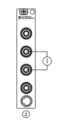
method 1 - created an input channel current analog & used a reading Vi to acquire it. How can I give the channel connections in this...
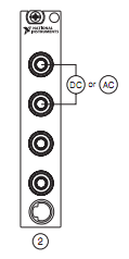
method 2 - using NOR-DAQ Assistant, I put the channel connections and I got Amplitude versus time graph. She also gave negative values. Can I do this way which is easier? How can I solve the problem
First attachment belongs to the 1st method
Second attachment belongs to the 2nd method
Tags: NI Hardware
Similar Questions
-
Can I use a power adapter that provides the samilar voltage but a different amperage?
Hi all
The specs for my original AC of a dv6-1355dx adator are:
Input: 100 ~ 240 V, 1.6 has, 50 - 60 Hz
Output: 18.5 3. 5 a, V
756
The plug of the adapter nearest you, that I could find online of dv6 is:
Input: 100 ~ 240 V, 1.5 has, 50 - 60 Hz
Output: 19 V 4.74
90W
Can I use it to replace the original one?
Thank you so much and have a nice weekend!
Yes, the HP Pavilion dv6-1355dx Entertainment Notebook PC comes with power adapter 65W.
http://support.HP.com/us-en/document/c01893242
The 90W AC adapter / you provided has no problem as long as the part fits, there are only two sizes (4,5 and 7. 4 mm).
To ensure that you get the compatible adapter, take a look at the
HP 65 w Smart AC adapter

For HP laptops with connectors 4.5 mm or 7. 4 mmhttp://www.shopping.HP.com/en_US/Home-Office/-/products/Accessories/AC-adapters/G6H42AA?HP-65W-smart-AC-adapter
Here are the following features and benefits to get the Smart AC adapter.
Smart cards can improve your productivity by feeding your computer laptop while that plugged in, as well as the charge of your battery so that you can take your laptop with you when you disconnect. HP Smart adapters also have built-in overvoltage protection to protect against current fluctuations that can damage your laptop. Help HP Smart adapters you can save on materials, energy consumption costs and travel.
-
Read the motor current by using the controller PXI-7350 and MID-7604
I use the PXI-7350 controller and MID-7604 drive to run a motor drive. I would like to be able to measure the motor current while moving the engines. This measurement is possible? If so, what commands are required to read the motor current?
Hi Casey,.
the 7604 can limit the current to a value that is selectable by the user and you can activate the current reduction if the axis is stopped, but there is no way to read the current engine. If you want to measure the motor current, you must do it with an external device, but due to the current chopping and multiphase, motor control stepper motors is not a trivial task. Micro step mode the current phase looks like a rough sinus with lots of harmonics signal, so you will need to do a true measure requiring RMS of expensive measurement equipment.
Anyway. If you need to know the temperature of the motor you should better measure the temperature directly. The most inexpensive device OR do is the NI USB-TC01, but there are many other options available.
Kind regards
Jochen
-
measure the speed of the fan in box vibration Simulator
I'm trying to measure the analog speed towards the sbRIO
I get a few signals pulse switching to 5v to 0v and vice versa with variable duty cycle...
How can I calculate the speed of the fan
values provided on the box of Simulator are
Tach 2 pulses/revolution
the maximum speed is 6,000 rpm
Please help me with this...
Did you look at the examples of LabVIEW? If you have installed the OR-DAQmx driver, you will find many examples showing how to do the counting of events or measures of frequency.
-
How to wire a pressure transducer loop 2 wires for the NI 9949 RJ - 50
I am new to the NC and data record.
I want to connect a 4/20mA, pressure sensor loop 2 son of a Terminal screw OR 9949 RJ - 50... that will then connect to an entrance NI 9237 module.
The NI 9237 module is installed in a chassis OR compact 9174 DAQ.
I shall be measure the pressures of air brakes truck to compressed air system of zero kPa (gauge pressure) up to allowance of 1000 kPa (gauge pressure).
The 2 wires on the transducer are identified as: food + and + signal
I would appreciate it please advice on the appropriate terminals on the NI 9949 RJ - 50
Unfortunately, it seems that you have the wrong module for this task. The 9237 is used to measure the production of bridge-based sensors (for example, a strain gauge). Signals that it is supposed to measure are fundamentally different from the 4-20mA signal pressure transducer outings.
Take a look at the NI 9203, 9207 or 9208. All have at least a few channels designed to take a current 4-20mA input. Then, give the team nor a (877-387-0015) call to talk through your application and make sure that you select the right equipment for what you want to do.
-
Measure the pressure with NI9205 in Mode CSR
I use the NI9205 module to measure the pressure, but when I connect two transducers of pressure for the module in the CSR mode there is a decrease of output signal of the pressure sensor and when I dissconnect it the signal to return to the previous value, also when I use the differential mode after a few seconds the output signal turns into a 50 Hz oscillation , can you help me please?
the pressure transducers are PDCR 4011, output 200mV and must provide of 10V and I use two similar power supply for transducers.
Thank you
Omid
Hello Omid,
It doesn't sound like the shields were inducing 50 Hz noise that you saw. They might have been picking up some other equipment in the room, and I think that Earth shield is the right solution for the problem.
Best regards
Adam G
-
using scxi 1303 and 1100 to measures of pressure
Hello
I use the scxi 1303 and 1100 to measure the voltage inputs. Specifically, I have 8 voltage at 0 - 10 v and 9 measures of pressure to 4-20mA, converted to signals 1 - 5V with a 250 Ohm resistor.
My arrises now question about pull upward resistance. I don't have resistance inserted (as the manual leads me to believe that they are not necessary). My arrises now problem of a difference in the voltage across the resistance (the same as the display of pressure transmitter) and the voltage displayed by Labview.
For example:
Voltage = 1.47 V
LabVIEW display = 1.18 V
1303/1100 Setup requires it resistance of 10 ohms, or don't you think that something is happening?
Thank you and please forgive me if this question has been addressed!
Good news... After much stable, time and tears I have solved the problem. I have indeed had a hardware issure. The module SCXI-1100 I used was broken somehow and was replaced by a functional SCXI-1102.
Thank you for helping me think about troubleshooting ideas!
-
Watch Apple should have is to measure the blood pressure?
The most important function that the Apple watch should have is to measure blood pressure.
All people who do physical activity or do not need this important function.
It makes no sense one shows that supports or has to help health
without this important mechanism.Cardiac measurement is more important at the time of registration or
or even stupid messages between people with Apple Watch.If there is to be a function of health, which will complete.
Thank you
Ulisses
Hi Ulisses
It is a community based on the user.
If you want to suggest that Apple consider adding monitoring of blood pressure as Apple Watch feature, you can do so here:
-
Hello
I am completely new to LABVIEW software.
I learn a LABVIEW code existing my pressure (attached) acquisition system which has the path of data as follows: pressure transducer Validyne--> Validyne CD280 - Dual--> SCB - 68--> PCI - 6024E--> LABVIEW and I have a few question:
1. How does the complete system of the transducer to the LABVIEW work? That is, if we apply the pressure of the transducer, it will change the resistance of the probe then...?
2. How can I find the equation that expresses the relationship between the pressure and the tension to the keys of the Validyne double-CD280 in the LABVIEW?
3. If I want to do the probe calibration, what are steps?
Thank you
You did not include most of the subVIs.
-
How to get mydaq recognize px309 pressure transducer % 3F
It has only 3 wires instead of the usual 4. They are black, red and white and negative excitement, positive excitement and signal respectively. I plugged the black wires and red to an external power supply, the white wire to the myDAQ HAVE. Then I went to labview, opened DQA assisntant - acquisition - tension - ai1. Then I put samples of continuous get ot and drew a graphical indicator and press the run button. Yet, the only signal I get is noise and graph (amplitude time vs) shows no change when pressure is applied.
Have you tried also runs the black wire from the transducer into one of the analog grounds on your MyDAQ? Measures data acquisition potential, without reference to ground the unit will not be able to measure anything.
You can also use an output on the analog MyDAQ to produce the voltage instead of using an external power supply.
I hope this helps.
-Nick-
-
6008 NI DAQ issues of reading pressure transducer
Hello everyone, I am a new user of labeled and not one expert on electronics, so please bear with me.
I'm trying to read a signal 4-20 my by a pressure transducer using a NI DAQ 6008 and Labview version 8.6. I am running Windows XP Professional. I'm the transducer, (http://www.omega.com/Pressure/pdf/PX01-I.pdf) providing a voltage of 10 v I have a 235 external resistance ohms between the terminals positive and negative data acquisition (although I am not sure that it is correct). At the start of my VI, I am able to measure a voltage of environ.9 data acquisition (verified by a voltmeter/ammeter) V and a current of environ.39 my.
My problem is the fact that when I have a supply pressure of my sensor, I have not received any signal whatsoever by the transducer, despite the fact that it is important that the pressure should give me a signal. Is this a problem with my installation, connections, data acquisition (which has been reset in MAX number of times and pass the self-test) or the sensor itself?
Thank you for your time and consideration
Hi prenerk,
You are right that resistance must be connected to the terminals positive and negative a way to HAVE to create a measured voltage to current. Here are two troubleshooting steps you can try:
1. check with an ammeter so you are detecting a change in the current when you apply pressure to the transducer.
2. open the Explorer Measurement & Automation and use a Test Panel to measure the voltage of the device. This will ensure that there is a mistake in your LabVIEW code. Also check the MAX pinout diagram to see if your sons are correctly plugged into the channel of GOT it.
If you have not discovered a problem with the above steps, we will have to learn more about your sensor pressure and how you connect it to the 6008. We will need the information on the sons of the Omega instrument and how they are connected to the excitation voltage source and 6008. Let us know how it goes!
Brian
-
I received an omega pressure sensor (model px309) with only three wires: Red (power supply +); Black (power supply)-; and white for the signal.
Should the output voltages of 0 to 5 and a voltage range from 9 to 30. It measures gage pressure.
I use a power supply that can output 12v to provide power to transduce and a Ni-9205 to collect the signal.
Red and black were connected to the power supply. The white one was hooked up to the ACH0 to collect the signal. In the test diifferential model, I used a wire to coneect to COM. ACH8 Also, I plugged the black wire pressure transduce to COM.
Is this the right settings?
I run my program and I found that the signal is not continuous, and it has a Variant. Please see attached picture.
Is this normal?
Hi Kang,
Depending on what beach you go the DAQmx task for the 9205, looks like expected behavior.
It seems that noise you see is on .1mV, which is quite close the specification of random noise for the NI 9205 module:http://www.ni.com/pdf/manuals/374188d.pdf#page=22
If you select a range of 0-5 v for example, DAQmx will put the module mode +-5V, which corresponds to a 116 uVrms noise, that seems pretty close to what you see.
-
Measure the current and voltage using DMM sharing a port
I want to measure pressure several times on a pcb, where I connect the ports of digital multimeters to the card using simple cards. Switching between the different voltages is done using simple. If the black port of DMM (the second from the top photo) is connected to the Earth to give the measure correct volt.
And then I want to measure current through different lines. The problem is here. Given that two measurement types share a port, how do I get the correct voltage and current measurement? The second port of top would be grounded, so I can't use the method of measuring the voltage across the line through a resistance with a known value, since then the second port must not be connected to the ground. How can I use the current state of the DMM measurement? How measure current? Are there examples of this? Tried looking through manuals, but could not find the good starting points.
so I can't use the method of measuring the voltage across the line through a resistance with a known value, since then the second port must not be connected to the ground.
On all of my games to test I have to mux my land of the signal along with the salvation of my signals.
All my mux test sets are set up for the topology 2-wire because there is no other way to do it without the weak side of switch also.
-
Hello
Does anyone have a pressure transducer with offset null simple vi constructed in code. I'm relatively new to labview and most of the examples I have seen are way to complex for me to understand what is happening. Is it better to use the DAQmx Wizard or data acquisition? I have two sensor of pressure (excitation omegadyne-10V) hung on to with a module for 1121 SCXI-1327. I wrote a program to convert mV to pressure using a linear scale, but that's all I know how to do at this point! And I want to know how to read the two transducers. Thank you!
Don't forget that you will need to change your excitement of inside out and remove the part with the shunt calibration.
-
How to wire NI 9203 to Emerson PT5 pressure transducer
Hi all
I started studying with 9188 OR cDAQ and analog input NI 9203 module. I'm really new on the DAQ hardware and I confused about my wiring for the NI 9203 pressure sensors. I want to use 6 pressure transducers whose output signals are ampere (4-20 my). In the manual operation of NI9203 shows that there is only 1 negative port (COM). Could I wire 1 more NI 9203 pressure sensors? If it is possible, how would I do that? The pressure transducers that I wanted to use a 2-wire and its technical specifications is Emerson PT5.
Hello
You should be able to branch out of the output of the power supply 24 VDC 8 drivers. Does that help?
-Carisa
Maybe you are looking for
-
Cannot display the guests of download in Firefox.
Monday, August 11, 2014 Hello... Currently, I encounter the following problem: I am unable to show guests of download in Firefox (version 31.0) whenever I try to download a patch, etc. from different sites. This question seems to have started with Fi
-
PC defender window will uninstall not msn will not uninstall, there is no program that can uninstall it on the Add/Remove program and he won't even be the arrow to the right to uninstall and I want just the program internet Explorer and nothing else.
-
I tried to search for the file, but no luck.
-
Problems with VCS - C, VCS - E and TMS
I hope someone can help me because I nearly pulled my hair with this problem. We have a VCS - C and VCS-E the two X7.2 running. Our TMS runs 13.2.1. We used it for several months with the 'transfer', which worked well. Recently, I am currently hav
-
Just got a new Dell laptop. Have restored to factory settings again. I am trying to upgrade to Win 7 home premium to win 7 professional. The first time I did it, it took place without a hitch. But this second everyone, it won't continue unless I turn